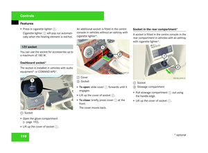
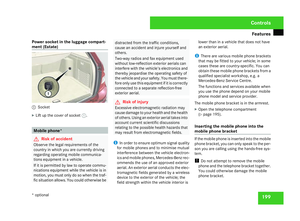
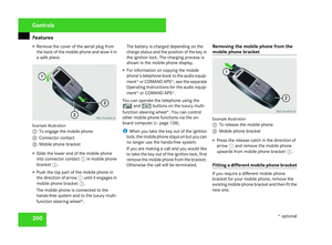
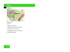
Page 65 of 377

Occupant safet
y62
ISOFIX child seat securing system in the
rea
r ISOFIX is a standardised securing system for
specially designed child restraint systems in
the rear. There are securing rings for two child
restraint systems on the left and right-hand
rear seats between the seat cushions and the
backrest.
G
Risk of injury
A child restraint system secured by the ISO-
FIX child seat securing system does not
provide sufficient protection for children
weighing more than 22 kg. For this reason,
do not secure children weighing more than
22 kg in a child restraint system secured by
the ISOFIX child seat securing system. If
the child weighs more than 22 kg, secure
the child restraint system using a lap-shoul-
der belt. G
Risk of injury
If a child restraint system is not fitted prop-
erly to a suitable seat in the vehicle, it
cannot provide its protective function. It
would not be possible to restrain the child
in the event of an accident, sudden braking
or a sudden change in direction. The child
could be seriously or even fatally injured . For this reason, observe the manufac-
turer’s installation instructions and correct
use when fitting the child restraint system.
On the rear seats, only use child restraint
systems with an ISOFIX child seat securing
system which have been recommended for
use in Mercedes-Benz vehicles .
An incorrectly fitted child restraint system
could come loose and seriously or eve n
fatally injure the child or other vehicle occu-
pants. When fitting the child restraint sys -
tem, make sure that it is engaged in the
securing rings on both sides. G
Risk of injury
Please note that child restraint systems
cannot provide a protective function if they
or their retaining systems are damaged or
have been subjected to a load in an acci -
dent. The child secured in this system could
be injured seriously or even fatally in the
event of an accident, sudden braking or a
sudden change in direction.
You must therefore have child restraint sys-
tems that are damaged or have been sub-
jected to a heavy load in an accident
checked immediately along with their
anchorages at a qualified specialist work-
shop. !
When fitting the child restraint system,
make sure that the seat belt for the middle
seat does not get trapped. It could other-
wise be damaged. Illustration showing a vehicle with through-loading
feature in the rear bench seat*
1
Securing ring s
TopTether
TopTether provides an additional connectio n
between the child restraint system secured
with ISOFIX and the rear seat. It helps reduce
the risk of injury even further.
The two TopTether anchorage points are loca-
ted on the rear shelf behind the outer head
restraints. Safet
y
* optional
204_AKB; 2; 3, en-GB
mkalafa,
2007-06-26T23:11:51+02:00 - Seite 62
Page 66 of 377

Occupant safet
y 63Saloon
1
Head restraint
2 Cove r
5 TopTether anchorage Estate
1
Head restraint
5 TopTether anchorage 3
TopTether belt* for the ISOFIX child
restraint system
4 TopTether hook*
5 Tether anchorage
X Move head restraint 1upwards.
X Guide TopTether belt *3 under head
restraint 1between the two head restraint
rods.
X Saloon: fold cover 2of TopTether anchor-
age 5up.
X All: hook TopTether hook* 4into Top-
Tether anchorage 5.
X Saloon: fold cover 2of TopTether anchor-
age 5down.
X All: move head restraints 1back down
again slightly if necessary (Y page 89). Make sure that you do not interfere with the
correct routing of TopTether belt*
3.
X Fit the ISOFIX child restraint system with
TopTether*. Comply with the manufactur-
er's installation instructions.
Integrated child seat* The child seats are integrated on the right and
left-hand sides of the seat cushion of the rea
r
bench seat. In connection with the side head
restraints (Y page 65) they comply with the
legal requirements of ECE R 44.04.
Mercedes-Benz recommends the integrated
child seat for children from approximately
two to twelve years or with a body weight of
12.5 kg to 36 kg.
For children between approximately two and
four years of age or weighing between
approximately 12.5 kg and 18 kg, you must
also use a padded table which has been spe-
cially approved for the integrated child seat. Safet
y
* optional
204_AKB; 2; 3, en-GB
mkalafa,
2007-06-26T23:11:51+02:00 - Seite 63 Z
Page 67 of 377

Occupant safet
y64 G
Risk of injury
To reduce the risk of serious or even fata l
injury to the child in the event of an acci-
dent, braking or sudden change in direc -
tion:
R you must follow the manufacturer' s
installation instructions for the child seat
when fitting the padded table and fas-
tening the seat belt.
R do not modify the integrated child seat or
padded table
R when the child seat is occupied, adjus t
the head restraint to a position in which
the back of the child's head is supporte d
by the centre of the head restraint at
about eye level.
R replace an integrated child seat or pad-
ded table that has been damaged or sub-
jected to a heavy load as the result of an
acciden t
R be aware that children under two years
of age require a different child restraint
system. Information about other child
restraint systems is available from any
Mercedes-Benz Service Centre.
R the rear seat backrest in the vehicle must
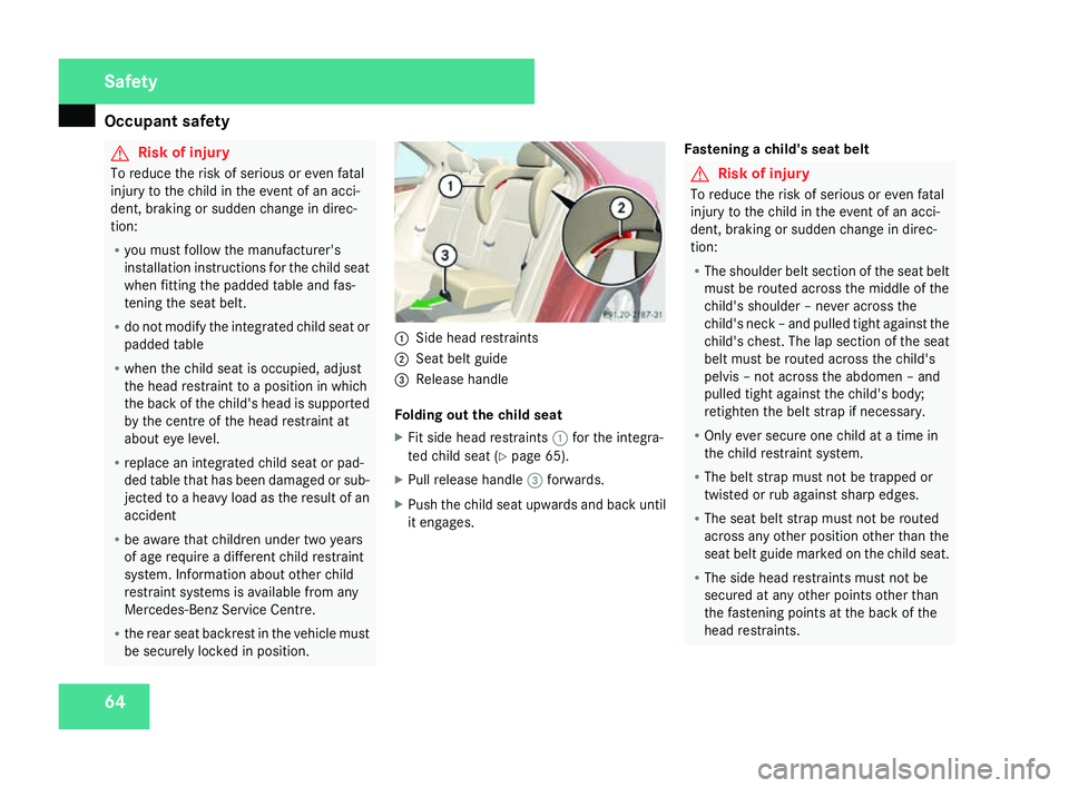
be securely locked in position. 1
Side head restraints
2 Seat belt guid e
3 Release handle
Folding out the child sea t
X Fit side head restraints 1for the integra -
ted child seat (Y page 65).
X Pull release handle 3forwards.
X Push the child seat upwards and back until
it engages. Fastening a child's seat belt G
Risk of injury
To reduce the risk of serious or even fata l
injury to the child in the event of an acci-
dent, braking or sudden change in direc -
tion:
R The shoulder belt section of the seat belt
must be routed across the middle of the
child's shoulder – never across the
child's neck – and pulled tight against the
child's chest. The lap section of the seat
belt must be routed across the child's
pelvis – not across the abdomen – and
pulled tight against the child's body;
retighten the belt strap if necessary.
R Only ever secure one child at a time in
the child restraint system.
R The belt strap must not be trapped or
twisted or rub against sharp edges.
R The seat belt strap must not be routed
across any other position other than the
seat belt guide marked on the child seat.
R The side head restraints must not be
secured at any other points other than
the fastening points at the back of the
head restraints. Safety
204_AKB; 2; 3, en-GB
mkalafa,
2007-06-26T23:11:51+02:00 - Seite 64
Page 68 of 377

Occupant safet
y 65Also observe the assembly instructions for
the padded table and the additional warn-
ings and information about risk of injury.
X Make sure that the seat belt is routed
through seat belt guides 2on side head
restraints 1.
X Pull the belt smoothly from the belt reel.
X Engage the belt tongue in the buckle .
X If the integrated child seat is being used
without the padded table, make sure that
the belt:
R is routed as low as possible across the
child's pelvic area
R is tightened across the lap by pulling
upwards on the child's shoulder belt
R is routed through seat belt guides 2on
side head restraints 1
R is tight and is routed across the middle of
the child's shoulder
R is not twisted and does not pass across the
child's neck or under the child's arm
X Adjust the head restraint (Y page 89). Folding in the child seat
X
Pull release handle 3forwards.
X Push the child seat back into the seat until
it engages.
X Remove side head restraints 1for the
integrated child seat (Y page 65).
Side head restraints for the integrated
child seat* The side head restraints must be used in con
-
nection with the integrated child sea t
( Y page 63).
i A side head restraint is fitted on vehicles
with integrated child seats*. Should mor e
be required, they can be ordered at any
Mercedes-Benz Service Centre. 1
Lock verification indicator folded out
2 Head restraint
3 Lock verification indicator folded in
4 Release catch
5 Seat belt guid e
6 Side head restraints
Fitting side head restraints G
Risk of injury
For safety reasons, Mercedes-Benz recom-
mends that you only use head restraints
which have been approved by Mercedes-
Benz for your vehicle.
X Slide head restraints 2upwards and posi -
tion them upright. Safety
* optional
204_AKB; 2; 3, en-G
B
mkalafa , 2007-06-26T23:11:51+02:00 - Seite 65 Z
Page 69 of 377

Occupant safet
y66
X
Slide side head restraints 6to the centr e
on both head restraint rods until they
engage.
The right and left lock verification indica-
tors 3must be folded in. The red surfaces
are no longer visible.
X Slide head restraints 2downwards
( Y page 89) until they rest on the upper
edge of side head restraints 6.
X Route the seat belt through seat belt guide
5 .
Removing the side head restraints
X Take the seat belt out of seat belt guide
5 .
X Move head restraint 2upwards.
X Press left and right release buttons 4and
pull forward side head restraints 6to
remove them.
The left and right lock verification indica -
tors 1fold out briefly .
X Adjust head restraints 2(Y page 89).
i On vehicles with TIREFIT kit, you can store
the side head restraints in the stowage
compartment under the boot/luggage compartment floor
(Y page 184)/
( Y page 184).
Child-proof locks If children are travelling in the vehicle, you can
activate the child-proof locks for the rear.
Child-proof locks for the rear doors
The child-proof locks on the rear doors enable
you to secure each door individually. You can-
not open a locked door from the inside. You
can open the door from the outside if the
vehicle is unlocked. G
Risk of injury
Activate the child-proof locks on the rea r
doors and deactivate the rear-compart -
ment window controls when children are
travelling in the vehicle. The children could
otherwise open doors or windows while the
vehicle is in motion, injuring themselve s
and others. Saloon shown as an example
1
To activat e
2 To deactivate
X To activate :press locking lever upwards
1 .
X Check the function of the child-proof locks .
X To deactivate :press locking lever down-
wards 2.
Child-proof locks for the rear windows G
Risk of injury
Activate the child-proof locks on the rea r
doors and deactivate the rear-compart -
ment window controls when children are
travelling in the vehicle. The children could
otherwise open doors or windows while the Safety
204_AKB; 2; 3, en-GB
mkalafa,
2007-06-26T23:11:51+02:00 - Seite 66
Page 70 of 377

Driving safety sys
tems 67vehicle is in motion, injuring themselves
and others . 1
Indicator lamp
2 Button
X To activate :press button 2.
Indicator lamp 1lights up. The rear side
windows can only be operated using the
switches on the driver's door.
X To deactivate :press button 2.
Indicator lamp 1goes out. You can oper-
ate the rear side windows using the
switches in the rear compartment. Driving safety systems
In this section, you will find information about
the following driving safety systems:
R ABS ( Anti-lock Braking System)
R BAS ( Brake Assist System)
R Adaptive brake lamps
R ESP ®
( Electronic Stability Program)
R EBV (electronic brake-power distribution)
i In wintry road conditions, use winter tyres
(M+S tyres) and snow chains if necessary. . G
Risk of accident
The risk of an accident is significantl y
increased by driving too fast. This is partic-
ularly the case when cornering on wet and
slippery roads and when driving too clos e
to the vehicle in front.
The driving safety systems described in thi s
section cannot reduce this risk or override
the laws of physics.
For this reason, always adapt your driving
style to suit the prevailing road and weather
conditions. Maintain sufficient distance
from other road users and objects on the
road. ABS (Anti-lock Braking System)
ABS regulates brake pressure in such a way
that the wheels do not lock when you brake.
This allows you to continue steering the vehi-
cle when braking.
ABS works from a speed of about 8 km/h
upwards, regardless of road surface condi-
tions. ABS works on slippery surfaces, even
when you only brake gently. G
Risk of accident
Do not depress the brake pedal severa l
times in quick succession (pumping) .
Depress the brake firmly and evenly. Pump-
ing the brake pedal reduces the braking
effect.
Braking If ABS intervenes when braking, you will fee
l
a pulsing in the brake pedal.
If ABS intervenes:
X Continue to depress the brake pedal wit h
force until the braking situation is over.
For full braking application:
X Depress the brake pedal with maximum
force. Safety
204_AKB; 2; 3, en-G
B
mkalafa , 2007-06-26T23:11:51+02:00 - Seite 67
Page 71 of 377

Driving safety sys
tems68 G
Risk of accident
If ABS is faulty, the wheels could lock when
braking. This limits the steerability of the
vehicle when braking and the braking dis-
tance may increase.
If ABS is deactivated due to a malfunction,
then BAS and ESP are also deactivated. BAS (Brake Assist)
BAS operates in emergency braking situa-
tions. If you depress the brake pedal quickly,
BAS automatically boosts the braking force ,
thus shortening the stopping distance.
X Keep the brake pedal firmly depressed until
the emergency braking situation is over.
ABS prevents the wheels from locking.
The brakes will function as usual once you
release the brake pedal. BAS is deactivated. G
Risk of accident
If BAS has malfunctioned, the braking sys-
tem remains available with full brake boost-
ing effect. However, braking force is not
automatically increased in emergency
braking situations and the stopping dis-
tance may increase. Adaptive brake lamps
i Adaptive brake lamps are only available in
certain countries.
If you brake sharply from a speed of mor e
than 50 km/h or if braking is assisted by BAS,
the brake lamps flash rapidly. In this way,
traffic travelling behind you is warned in an
even more noticeable manner .
If you brake from a speed of more than
70 km/h and bring the vehicle to a halt, the
hazard warning lamps switch on automati-
cally once the vehicle is stationary and the
brake lamps light up constantly if you depres s
the brake pedal again. The hazard warning
lamps switch off automatically if you travel
faster than 10 km/h again. ES
P®
(Electronic Stability Program)
ES P®
monitors driving stability and traction,
i.e. power transmission between the tyres
and the road surface.
If ESP ®
detects that the vehicle is deviatin g
from the direction desired by the driver, one
or more wheels are braked to stabilise the
vehicle. The engine output is also modified, if
necessary, to keep the vehicle on the desired
course within the laws of physics. ESP assists
the driver when pulling away on wet or slip-
pery roads. ESP ®
can also stabilise the vehi-
cle during braking.
When ESP ®
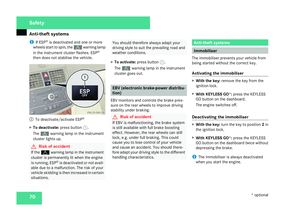
intervenes, the vwarning
lamp flashes in the instrument cluster. G
Risk of accident
If the v warning lamp in the instrumen t
cluster flashes, proceed as follows:
R Do not deactivate ESP ®
under any cir -
cumstances .
R Only depress the accelerator pedal as far
as necessary when pulling away.
R Adapt your driving style to suit the pre -
vailing road and weather conditions.
The vehicle could otherwise go into a skid. Safety
204_AKB; 2; 3, en-GB
mkalafa,
2007-06-26T23:11:51+02:00 - Seite 68
Page 72 of 377

Driving safety sys
tems 69ESP
®
cannot reduce the risk of an accident
if you drive too fast. ESP ®
cannot overrid e
the laws of physics .
! If the vehicle is to be towed with the front
or rear axle raised, the ignition must be
switched off (key in position 0or 1in the
ignition lock). Application of the brakes by
ESP ®
could otherwise destroy the brake
system on the front or rear axle.
! Vehicles with 4MATIC* may not be towe d
with the front or rear axle raised .
i Only use wheels with the recommended
tyre sizes. Only then will ESP ®
function
properly .
ESP ®
trailer stabilisin g If your trailer begins to lurch, you can only
stabilise the vehicle/trailer combination by
depressing the brake firmly .
In this situation, ESP ®
assists you and detect s
if the trailer begins to snake. ES P®
slows the
vehicle down by braking and limiting the
engine output until the vehicle/trailer com-
bination has stabilised. Trailer stabilising is active from about
65 km/h. G
Risk of accident
If the road and weather conditions are bad,
trailer stabilising will not be able to prevent
the trailer from lurching or reduce the ris k
of accident. Trailers with a high centre of
gravity can tip over before ESP ®
can detect
this .
Trailer stabilising does not work if ESP ®
is
deactivated or switched off because of a mal-
function .
ETS (Electronic Traction Support) Traction control is part of ES
P®
.
Traction control brakes the drive wheels indi-
vidually if they spin. This enables you to pull
away and accelerate on slippery surfaces, for
example if the road surface is slippery on one
side.
Traction control remains active when you
deactivate ESP ®
. G
Risk of accident
Traction control cannot reduce the risk of
an accident if you drive too fast. Traction
control cannot override the laws of physics .Deactivating/activating ESP
® ESP
®
is activated automatically when the
engine is running.
It may be best to deactivate ES P®
in the fol-
lowing situations:
R when using snow chain s
R in deep sno w
R on sand or gravel G
Risk of accident
Activate ESP ®
as soon as the reason for
deactivation is longer present. ES P®
will
otherwise not be able to stabilise the vehi -
cle if the vehicle starts to skid or a wheel
starts to spin.
If you deactivate ESP ®
:
R ESP ®
no longer improves driving stability.
R The engine's torque is no longer limited and
the drive wheels can spin. The spinning of
the wheels results in a cutting action, which
provides better grip.
R Traction control is still activated.
R ESP ®
still provides support when you
brake. Safety
* optional
204_AKB; 2; 3, en-GB
mkalafa,
2007-06-26T23:11:51+02:00 - Seite 69