Page 1454 of 6020
6A-94 ENGINE MECHANICAL (4JK1/4JJ1)
24. Install the camshaft assembly.
• Align timing mark on intake camshaft and
exhaust camshaft to idle gear D.
RTW 56ASH007001
Legend
1. Exhaust Camshaft Gear
2. Intake Camshaft Gear
3. Idle Gear D
25. Install the camshaft bearing cap.
•
Apply engine oil to all of the cylinder head
journals.
RTW 56ASH013801
Tightening torque: 18 N ⋅
⋅⋅
⋅
m (1.8 kg ⋅
⋅⋅
⋅
m / 13 lb ft)
26. Align mark on camshaft to mark on camshaft
bearing cap.
• Align mark (1) on intake camshaft and exhaust
camshaft to mark of bearing cap.
RTW 56ASH006901
27. Remove the lock bolt from the camshaft gear.
28. Turn the crank pulley two rotation (720 °CA).
• Align mark on camshaft to mark on camshaft
bearing cap.
RTW 56ASH020701
Legend
1. Exhaust Camshaft Gear
2. Intake Camshaft Gear
3. Idle Gear D
BACK TO CHAPTER INDEX
TO MODEL INDEX
ISUZU KB P190 2007
Page 1455 of 6020

ENGINE MECHANICAL (4JK1/4JJ1) 6A-95
RTW 56ASH020301
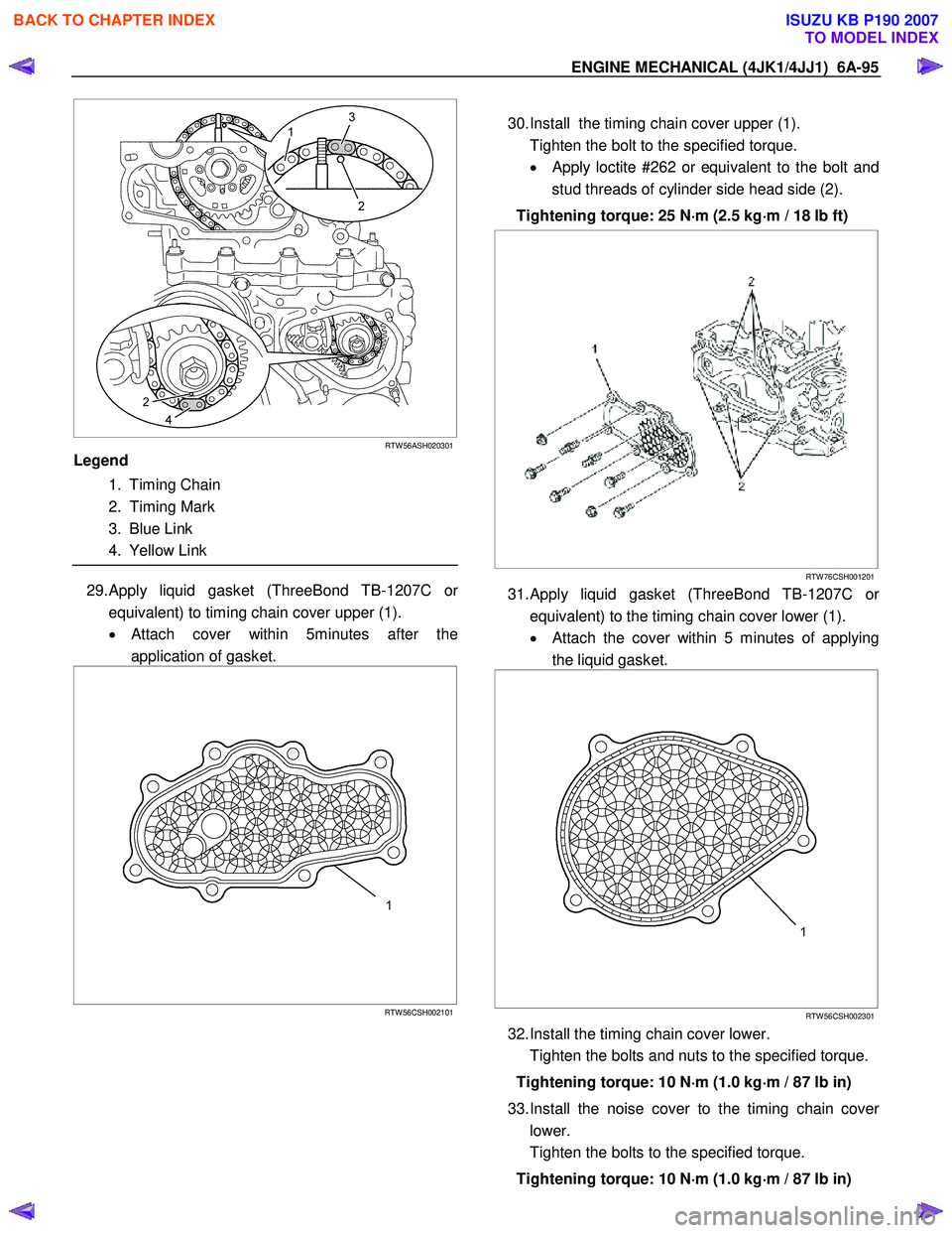
Legend
1. Timing Chain
2. Timing Mark
3. Blue Link
4. Yellow Link
29. Apply liquid gasket (ThreeBond TB-1207C or
equivalent) to timing chain cover upper (1).
• Attach cover within 5minutes after the
application of gasket.
RTW 56CSH002101
30. Install the timing chain cover upper (1).
Tighten the bolt to the specified torque. •
Apply loctite #262 or equivalent to the bolt and
stud threads of cylinder side head side (2).
Tightening torque: 25 N ⋅
⋅⋅
⋅
m (2.5 kg ⋅
⋅⋅
⋅
m / 18 lb ft)
RTW 76CSH001201
31. Apply liquid gasket (ThreeBond TB-1207C or
equivalent) to the timing chain cover lower (1).
• Attach the cover within 5 minutes of applying
the liquid gasket.
RTW 56CSH002301
32. Install the timing chain cover lower.
Tighten the bolts and nuts to the specified torque.
Tightening torque: 10 N ⋅
⋅⋅
⋅
m (1.0 kg ⋅
⋅⋅
⋅
m / 87 lb in)
33. Install the noise cover to the timing chain cove
r
lower.
Tighten the bolts to the specified torque.
Tightening torque: 10 N ⋅
⋅⋅
⋅
m (1.0 kg ⋅
⋅⋅
⋅
m / 87 lb in)
BACK TO CHAPTER INDEX
TO MODEL INDEX
ISUZU KB P190 2007
Page 1456 of 6020
6A-96 ENGINE MECHANICAL (4JK1/4JJ1)
34. Inspection / adjustment of valve clearance.
• Refer to procedure for Service Precautions in
this manual.
35. Install the fuel injector. • Refer to procedure for Fuel System in this
manual.
36. Install the baffle cover. • Refer to procedure for Camshaft Assembly in
this manual.
37. Install the cam end gasket. • Apply the liquid gasket (ThreeBond TB-1207B
or equivalent).
RTW 56ASH020601
Legend
1. Cam End Gasket
2. 2.0 - 3.0 mm (0.078 - 0.118 in)
38. Install the cylinder head cover.
Refer to procedure for Cylinder Head Cover in this manual.
39. Install the glow plug .
Tighten the glow plug to the specified torque.
Tightening torque: 18 N ⋅
⋅⋅
⋅
m (1.8 kg ⋅
⋅⋅
⋅
m / 13 lb ft)
40. Install the glow plug connector.
Tighten the nut to the specified torque.
Tightening torque: 2 N ⋅
⋅⋅
⋅
m (0.2 kg ⋅
⋅⋅
⋅
m / 17 lb in)
RTW 56ASH010201
Legend
1. Glow Plug Connector
2. Nut
BACK TO CHAPTER INDEX
TO MODEL INDEX
ISUZU KB P190 2007
Page 1457 of 6020

ENGINE MECHANICAL (4JK1/4JJ1) 6A-97
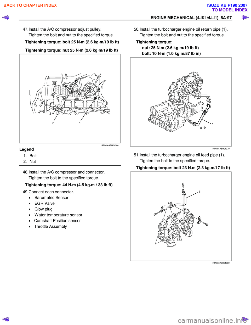
47. Install the A/C compressor adjust pulley.
Tighten the bolt and nut to the specified torque.
Tightening torque: bolt 25 N ⋅
⋅⋅
⋅
m (2.6 kg ⋅
⋅⋅
⋅
m/19 lb ft)
Tightening torque: nut 25 N ⋅
⋅⋅
⋅
m (2.6 kg ⋅
⋅⋅
⋅
m/19 lb ft)
RTW 56ASH010601
Legend
1. Bolt
2. Nut
48. Install the A/C compressor and connector.
Tighten the bolt to the specified torque.
Tightening torque: 44 N ⋅
⋅⋅
⋅
m (4.5 kg ⋅
⋅⋅
⋅
m / 33 lb ft)
49. Connect each connector. • Barometric Sensor
• EGR Valve
• Glow plug
• W ater temperature sensor
• Camshaft Position sensor
• Throttle Assembly
50. Install the turbocharger engine oil return pipe (1).
Tighten the bolt and nut to the specified torque.
Tightening torque: nut: 25 N ⋅
⋅⋅
⋅
m (2.6 kg ⋅
⋅⋅
⋅
m/19 lb ft)
bolt: 10 N ⋅
⋅⋅
⋅
m (1.0 kg ⋅
⋅⋅
⋅
m/87 lb in)
RTW 56ASH010701
51. Install the turbocharger engine oil feed pipe (1).
Tighten the bolt to the specified torque.
Tightening torque: bolt 23 N ⋅
⋅⋅
⋅
m (2.3 kg ⋅
⋅⋅
⋅
m/17 lb ft)
RTW 56ASH010801
BACK TO CHAPTER INDEX
TO MODEL INDEX
ISUZU KB P190 2007
Page 1458 of 6020

6A-98 ENGINE MECHANICAL (4JK1/4JJ1)
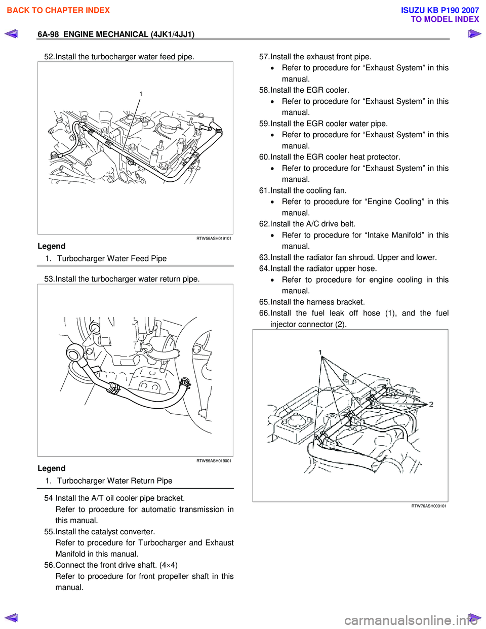
52. Install the turbocharger water feed pipe.
RTW 56ASH019101
Legend
1. Turbocharger W ater Feed Pipe
53. Install the turbocharger water return pipe.
RTW 56ASH019001
Legend
1. Turbocharger W ater Return Pipe
54 Install the A/T oil cooler pipe bracket.
Refer to procedure for automatic transmission in this manual.
55. Install the catalyst converter.
Refer to procedure for Turbocharger and Exhaust Manifold in this manual.
56. Connect the front drive shaft. (4 ×4)
Refer to procedure for front propeller shaft in this manual.
57. Install the exhaust front pipe.
• Refer to procedure for “Exhaust System” in this
manual.
58. Install the EGR cooler. • Refer to procedure for “Exhaust System” in this
manual.
59. Install the EGR cooler water pipe. • Refer to procedure for “Exhaust System” in this
manual.
60. Install the EGR cooler heat protector. • Refer to procedure for “Exhaust System” in this
manual.
61. Install the cooling fan. • Refer to procedure for “Engine Cooling” in this
manual.
62.Install the A/C drive belt. • Refer to procedure for “Intake Manifold” in this
manual.
63. Install the radiator fan shroud. Upper and lower.
64. Install the radiator upper hose. • Refer to procedure for engine cooling in this
manual.
65. Install the harness bracket.
66. Install the fuel leak off hose (1), and the fuel injector connector (2).
RTW 76ASH000101
BACK TO CHAPTER INDEX
TO MODEL INDEX
ISUZU KB P190 2007
Page 1459 of 6020
ENGINE MECHANICAL (4JK1/4JJ1) 6A-99
67.Install the intercooler (High output).
• Install the intercooler.
• Install the two intake hoses.
• Connect the BARO sensor harness connector.
68. Install the intake hose.
RTW 56ASH022501
Legend
1. Intake Hose for Intercooler and Intake Throttle
2. Intake Duct for Turbocharger and Air Cleaner
3. Intake Hose for Turbocharger and Intercooler
69. Install the engine head cover.
70. Replenish the coolant.
BACK TO CHAPTER INDEX
TO MODEL INDEX
ISUZU KB P190 2007
Page 1460 of 6020
6A-100 ENGINE MECHANICAL (4JK1/4JJ1)
Torque Specifications
RTW 76AMF000201
Special Tools
ILLUSTRATION PART NO.
PART NAME
ILLUSTRATION PART NO.
PART NAME
5-8840-2820-0
Injection pipe oil seal installer
5-8840-0266-0
Angle gauge
5-8840-2816-0
Valve guide remover and installer
BACK TO CHAPTER INDEX
TO MODEL INDEX
ISUZU KB P190 2007
Page 1461 of 6020
ENGINE MECHANICAL (4JK1/4JJ1) 6A-101
Piston and Connecting Rod
Components
RTW A56ALF001601
Legend 1. Piston Pin Snap Ring
2. Piston Pin
3. Piston Ring 4. Piston
5. Connecting Rod
6. Bearing
Removal
1. Demount the engine assembly.
Refer to “Engine Assembly”.
2. Remove the cylinder head cover.
Refer to “Cylinder Head Cover”.
3. Remove the camshaft assembly.
Refer to “Camshaft Assembly”.
4. Remove the cylinder head.
Refer to “Cylinder Head”.
5. Remove the gear case assembly.
Refer to “Gear Case Assembly”.
6. Remove the oil pan.
Refer to “Oil Pan” .
7. Remove the connecting rod cap.
BACK TO CHAPTER INDEX
TO MODEL INDEX
ISUZU KB P190 2007