Page 1422 of 6020
6A-62 ENGINE MECHANICAL (4JK1/4JJ1)
3. Remove the dowel pin.
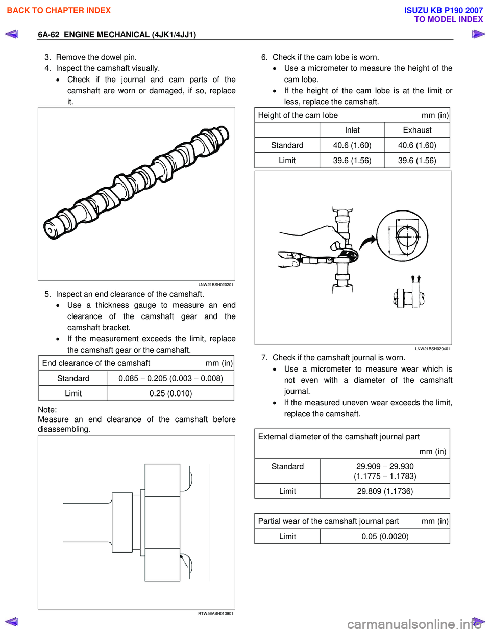
4. Inspect the camshaft visually. • Check if the journal and cam parts of the
camshaft are worn or damaged, if so, replace
it.
LNW 21BSH020201
5. Inspect an end clearance of the camshaft.
• Use a thickness gauge to measure an end
clearance of the camshaft gear and the
camshaft bracket.
• If the measurement exceeds the limit, replace
the camshaft gear or the camshaft.
End clearance of the camshaft mm (in)
Standard 0.085 − 0.205 (0.003 − 0.008)
Limit 0.25 (0.010)
Note:
Measure an end clearance of the camshaft before
disassembling.
RTW 56ASH013901
6. Check if the cam lobe is worn.
• Use a micrometer to measure the height of the
cam lobe.
• If the height of the cam lobe is at the limit o
r
less, replace the camshaft.
Height of the cam lobe mm (in)
Inlet Exhaust
Standard 40.6 (1.60) 40.6 (1.60)
Limit 39.6 (1.56) 39.6 (1.56)
LNW 21BSH020401
7. Check if the camshaft journal is worn.
• Use a micrometer to measure wear which is
not even with a diameter of the camshaft
journal.
• If the measured uneven wear exceeds the limit,
replace the camshaft.
External diameter of the camshaft journal part
mm (in)
Standard 29.909 − 29.930
(1.1775 − 1.1783)
Limit 29.809 (1.1736)
Partial wear of the camshaft journal part mm (in)
Limit 0.05 (0.0020)
BACK TO CHAPTER INDEX
TO MODEL INDEX
ISUZU KB P190 2007
Page 1423 of 6020
ENGINE MECHANICAL (4JK1/4JJ1) 6A-63
LNW 21BSH020501
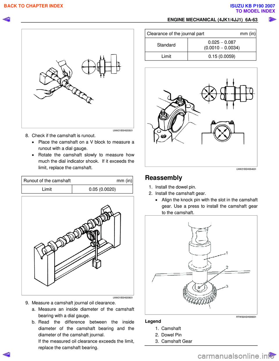
8. Check if the camshaft is runout.
• Place the camshaft on a V block to measure a
runout with a dial gauge.
• Rotate the camshaft slowly to measure ho
w
much the dial indicator shook. If it exceeds the
limit, replace the camshaft.
Runout of the camshaft mm (in)
Limit 0.05 (0.0020)
LNW 21BSH020601
9. Measure a camshaft journal oil clearance.
a. Measure an inside diameter of the camshaft bearing with a dial gauge.
b. Read the difference between the inside diameter of the camshaft bearing and the
diameter of the camshaft journal.
If the measured oil clearance exceeds the limit, replace the camshaft bearing.
Clearance of the journal part mm (in)
Standard 0.025
− 0.087
(0.0010 − 0.0034)
Limit 0.15 (0.0059)
LNW 21BSH054601
Reassembly
1. Install the dowel pin.
2. Install the camshaft gear. • Align the knock pin with the slot in the camshaft
gear. Use a press to install the camshaft gea
r
to the camshaft.
RTW 56ASH006601
Legend
1. Camshaft
2. Dowel Pin
3. Camshaft Gear
BACK TO CHAPTER INDEX
TO MODEL INDEX
ISUZU KB P190 2007
Page 1424 of 6020
6A-64 ENGINE MECHANICAL (4JK1/4JJ1)
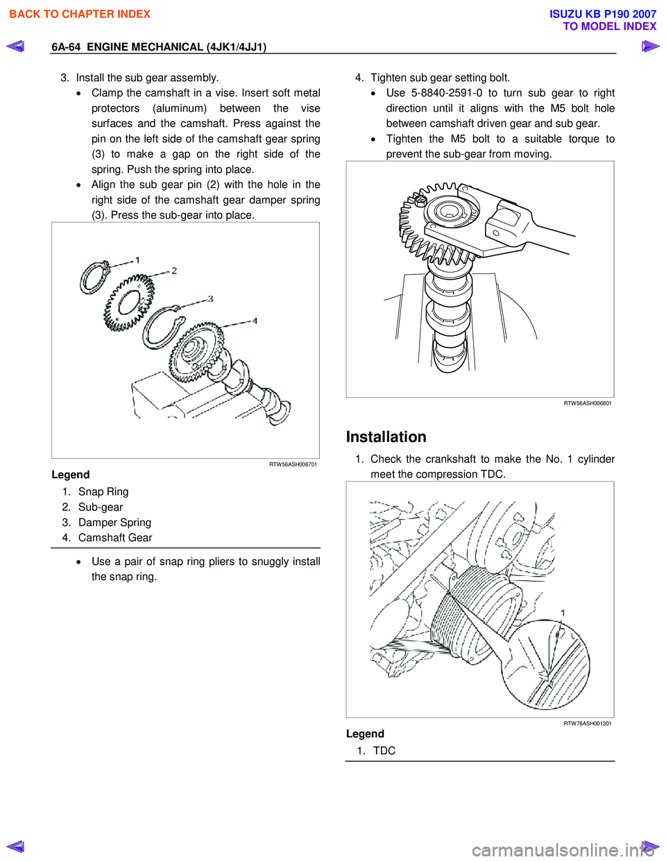
3. Install the sub gear assembly.
• Clamp the camshaft in a vise. Insert soft metal
protectors (aluminum) between the vise
surfaces and the camshaft. Press against the
pin on the left side of the camshaft gear spring
(3) to make a gap on the right side of the
spring. Push the spring into place.
• Align the sub gear pin (2) with the hole in the
right side of the camshaft gear damper spring
(3). Press the sub-gear into place.
RTW 56ASH006701
Legend
1. Snap Ring
2. Sub-gear
3. Damper Spring
4. Camshaft Gear
• Use a pair of snap ring pliers to snuggly install
the snap ring.
4. Tighten sub gear setting bolt.
• Use 5-8840-2591-0 to turn sub gear to right
direction until it aligns with the M5 bolt hole
between camshaft driven gear and sub gear.
• Tighten the M5 bolt to a suitable torque to
prevent the sub-gear from moving.
RTW 56ASH006801
Installation
1. Check the crankshaft to make the No. 1 cylinder
meet the compression TDC.
RTW 76ASH001301
Legend
1. TDC
BACK TO CHAPTER INDEX
TO MODEL INDEX
ISUZU KB P190 2007
Page 1425 of 6020
ENGINE MECHANICAL (4JK1/4JJ1) 6A-65
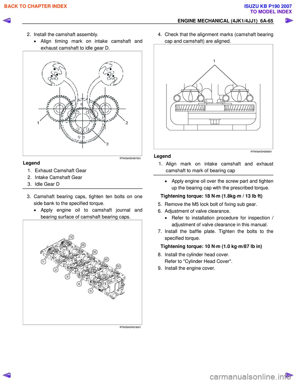
2. Install the camshaft assembly.
• Align timing mark on intake camshaft and
exhaust camshaft to idle gear D.
RTW 56ASH007001
Legend
1. Exhaust Camshaft Gear
2. Intake Camshaft Gear
3. Idle Gear D
3. Camshaft bearing caps, tighten ten bolts on one
side bank to the specified torque.
• Apply engine oil to camshaft journal and
bearing surface of camshaft bearing caps.
RTW 56ASH018401
4. Check that the alignment marks (camshaft bearing
cap and camshaft) are aligned.
RTW 56ASH006901
Legend
1.
Align mark on intake camshaft and exhaust
camshaft to mark of bearing cap
• Apply engine oil over the screw part and tighten
up the bearing cap with the prescribed torque.
Tightening torque: 18 N ⋅
⋅⋅
⋅
m (1.8kg ⋅
⋅⋅
⋅
m / 13 lb ft)
5. Remove the M5 lock bolt of fixing sub gear.
6. Adjustment of valve clearance. • Refer to installation procedure for inspection
/
adjustment of valve clearance in this manual.
7. Install the baffle plate. Tighten the bolts to the specified torque.
Tightening torque: 10 N ⋅
⋅⋅
⋅
m (1.0 kg ⋅
⋅⋅
⋅
m/87 lb in)
8. Install the cylinder head cover.
Refer to "Cylinder Head Cover".
9. Install the engine cover.
BACK TO CHAPTER INDEX
TO MODEL INDEX
ISUZU KB P190 2007
Page 1426 of 6020
6A-66 ENGINE MECHANICAL (4JK1/4JJ1)
Torque Specifications
RTW 56AMF001701
Special Tools
ILLUSTRATION PART NO.
PART NAME
5-8840-2591-0
Camshaft gear tool
BACK TO CHAPTER INDEX
TO MODEL INDEX
ISUZU KB P190 2007
Page 1427 of 6020
ENGINE MECHANICAL (4JK1/4JJ1) 6A-67
Valve Stem Seal and Valve Spring
Components
RTW 56ALF001301
Legend 1. Exhaust Rocker Arm Shaft Assembly
2. Bolt (Long)
3. Bolt (Short)
4. Intake Rocker Arm Shaft Assembly
5. Fuel Injector Assembly
6. Bolt
7. Fuel Injector Clamp 8. Pin
9. Spring Lower Seat
10. Valve Stem Oil Seal
11. Valve Spring
12. Spring Upper Seat
13. Split Collar
14. Valve Stem End Cap
BACK TO CHAPTER INDEX
TO MODEL INDEX
ISUZU KB P190 2007
Page 1428 of 6020
6A-68 ENGINE MECHANICAL (4JK1/4JJ1)
Removal
1. Remove the cylinder head.
Refer to “Cylinder Head”.
2. Remove the split collar. • Use a replacer to compress the valve spring to
remove the split collar.
Special tool
Valve spring replacer: 5-8840-2818-0 (1)
Pivot assembly: 5-8840-2819-0 (2)
RTW 56ASH012301
3. Remove the spring upper seat.
• Remove the special tool to remove the uppe
r
seat.
4. Remove the valve spring. Put the removed valve springs in order b
y
cylinder number.
5. Remove the valve stem oil seal. • Use pliers to remove the oil seal.
RTW 56ASH012401
Note:
Do not use the removed oil seal again.
6. Remove the spring lower seat.
BACK TO CHAPTER INDEX
TO MODEL INDEX
ISUZU KB P190 2007
Page 1429 of 6020
ENGINE MECHANICAL (4JK1/4JJ1) 6A-69
Inspection
Inspect the valve spring
Note:
Check the valve spring visually and if there is clea
r
damage or wear, replace it.
1. Free length • Measure free length of the spring and if it is
shorter than the prescribed limit, replace the
spring.
Free length of the valve spring
mm (in)
Inlet / Exhaust
Standard 49.04 (1.93)
Limit 48.15 (1.89)
LNW 21BSH017001
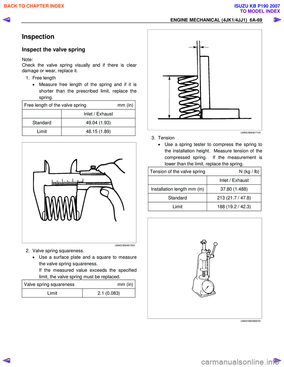
2. Valve spring squareness.
• Use a surface plate and a square to measure
the valve spring squareness.
If the measured value exceeds the specified limit, the valve spring must be replaced.
Valve spring squareness mm (in)
Limit 2.1 (0.083)
LNW 21BSH017101
3. Tension
• Use a spring tester to compress the spring to
the installation height. Measure tension of the
compressed spring. If the measurement is
lower than the limit, replace the spring.
Tension of the valve spring N (kg / lb)
Inlet / Exhaust
Installation length mm (in) 37.80 (1.488)
Standard 213 (21.7 / 47.8)
Limit 188 (19.2 / 42.3)
LNW 21BSH056701
BACK TO CHAPTER INDEX
TO MODEL INDEX
ISUZU KB P190 2007