Page 1486 of 6020
6A-126 ENGINE MECHANICAL (4JK1/4JJ1)
Crankshaft
Components
RTW 56ALF002601
Legend
1. Upper Bearing
2. Thrust Bearing
3. Gear 4. Crankshaft
5. Lower Bearing
6. Bearing Cap
BACK TO CHAPTER INDEX
TO MODEL INDEX
ISUZU KB P190 2007
Page 1487 of 6020
ENGINE MECHANICAL (4JK1/4JJ1) 6A-127
Removal
1. Demount the engine assembly.
Refer to "Engine Assembly".
2. Remove the cylinder head cover.
Refer to "Cylinder Head Cover".
3. Remove the camshaft.
Refer to "Camshaft Assembly".
4. Remove the cylinder head.
Refer to "Cylinder Head".
5. Remove the fuel supply pump and fuel rail.
Refer to "Fuel Supply Pump" and "Fuel Rail" in the fuel system section.
6. Remove the front cover.
Refer to "Front Cover".
7. Remove the crankshaft rear oil seal.
Refer to "Crankshaft Rear Oil Seal".
8. Remove the water pump.
Refer to "W ater Pump" in Cooling System Section.
9. Remove the timing gear train.
Refer to "Timing Gear Train".
10.Remove the oil pump.
Refer to "Oil Pump".
11. Remove the gear case assembly.
Refer to “Gear Case Assembly”.
12. Remove the crankshaft gear.
901R100008
13. Remove the crank case.
Refer to "Crank Case and Oil Pan".
14.Remove pistons and connecting rods.
Refer to "Piston and Connecting Rod".
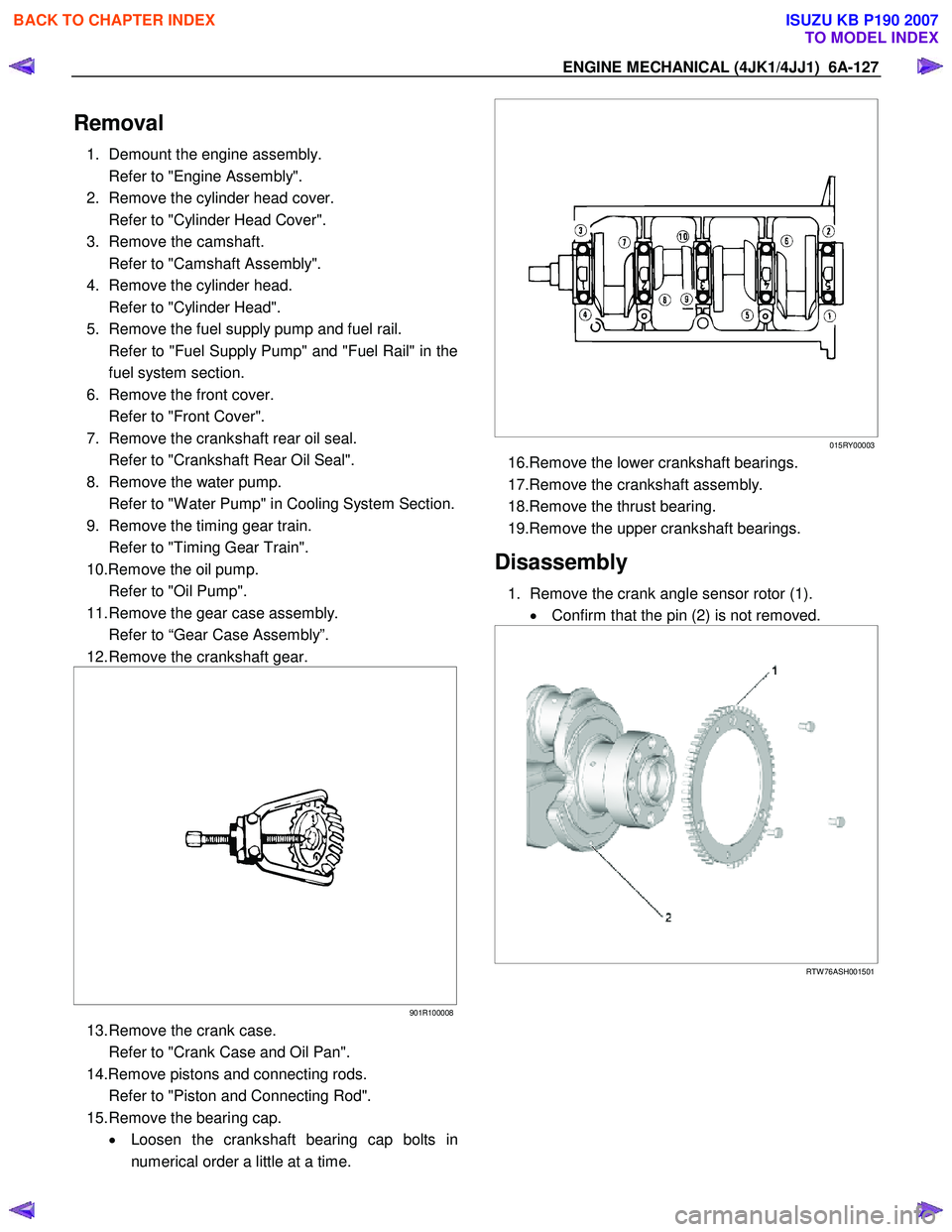
15. Remove the bearing cap. • Loosen the crankshaft bearing cap bolts in
numerical order a little at a time.
015RY00003
16.Remove the lower crankshaft bearings.
17.Remove the crankshaft assembly.
18.Remove the thrust bearing.
19.Remove the upper crankshaft bearings.
Disassembly
1. Remove the crank angle sensor rotor (1). • Confirm that the pin (2) is not removed.
RTW 76ASH001501
BACK TO CHAPTER INDEX
TO MODEL INDEX
ISUZU KB P190 2007
Page 1488 of 6020
6A-128 ENGINE MECHANICAL (4JK1/4JJ1)
Reassembly
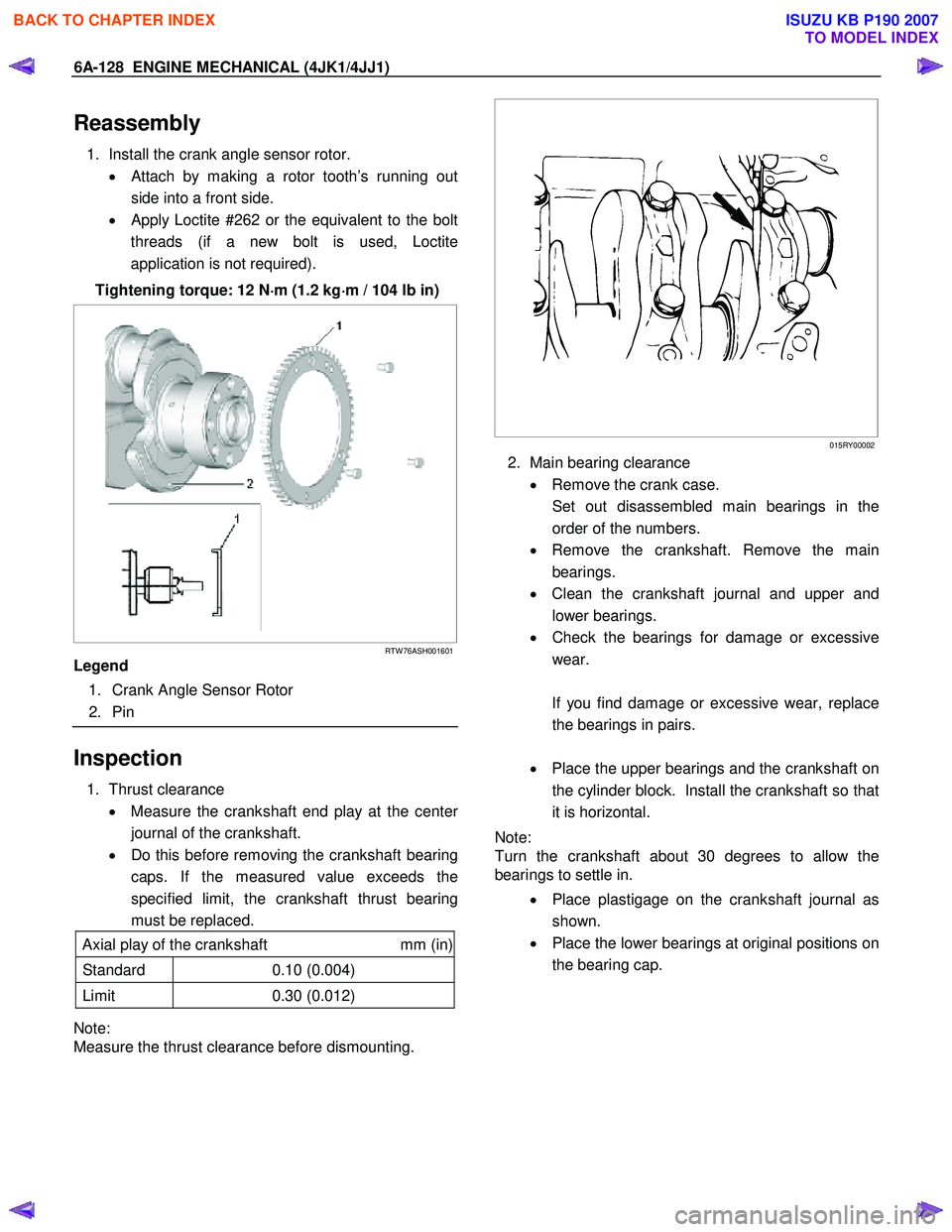
1. Install the crank angle sensor rotor.
• Attach by making a rotor tooth’s running out
side into a front side.
•
Apply Loctite #262 or the equivalent to the bolt
threads (if a new bolt is used, Loctite
application is not required).
Tightening torque: 12 N ⋅
⋅⋅
⋅
m (1.2 kg ⋅
⋅⋅
⋅
m / 104 lb in)
RTW 76ASH001601
Legend
1. Crank Angle Sensor Rotor
2. Pin
Inspection
1. Thrust clearance
• Measure the crankshaft end play at the cente
r
journal of the crankshaft.
• Do this before removing the crankshaft bearing
caps. If the measured value exceeds the
specified limit, the crankshaft thrust bearing
must be replaced.
Axial play of the crankshaft mm (in)
Standard 0.10 (0.004)
Limit 0.30 (0.012)
Note:
Measure the thrust clearance before dismounting.
015RY00002
2. Main bearing clearance
• Remove the crank case.
Set out disassembled main bearings in the order of the numbers.
• Remove the crankshaft. Remove the main
bearings.
• Clean the crankshaft journal and upper and
lower bearings.
• Check the bearings for damage or excessive
wear.
If you find damage or excessive wear, replace the bearings in pairs.
• Place the upper bearings and the crankshaft on
the cylinder block. Install the crankshaft so that
it is horizontal.
Note:
Turn the crankshaft about 30 degrees to allow the
bearings to settle in.
• Place plastigage on the crankshaft journal as
shown.
• Place the lower bearings at original positions on
the bearing cap.
BACK TO CHAPTER INDEX
TO MODEL INDEX
ISUZU KB P190 2007
Page 1489 of 6020
ENGINE MECHANICAL (4JK1/4JJ1) 6A-129
015RY00012
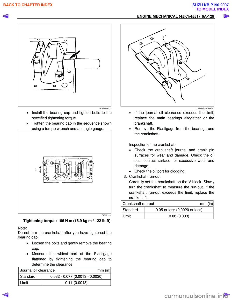
• Install the bearing cap and tighten bolts to the
specified tightening torque.
• Tighten the bearing cap in the sequence shown
using a torque wrench and an angle gauge.
015LX129
Tightening torque: 166 N ⋅
⋅⋅
⋅
m (16.9 kg ⋅
⋅⋅
⋅
m / 122 lb ft)
Note:
Do not turn the crankshaft after you have tightened the
bearing cap.
• Loosen the bolts and gently remove the bearing
cap.
• Measure the widest part of the Plastigage
flattened by tightening the bearing cap to
determine the clearance.
Journal oil clearance mm (in)
Standard 0.032 - 0.077 (0.0013 - 0.0030)
Limit 0.11 (0.0043)
LNW 21BSH024401
•
If the journal oil clearance exceeds the limit,
replace the main bearings altogether or the
crankshaft.
• Remove the Plastigage from the bearings and
the crankshaft.
Inspection of the crankshaft
• Check the crankshaft journal and crank pin
surfaces for wear and damage. Check the oil
seal contact surface for excessive wear and
damage.
• Check the oil port for clogging.
3. Crankshaft run-out
Carefully set the crankshaft on the V block. Slowl
y
turn the crankshaft to measure the run-out. If the
crankshaft run-out exceeds the limit, replace the
crankshaft.
Crankshaft run-out mm (in)
Standard 0.05 or less (0.0020 or less)
Limit 0.08 (0.003)
BACK TO CHAPTER INDEX
TO MODEL INDEX
ISUZU KB P190 2007
Page 1490 of 6020
6A-130 ENGINE MECHANICAL (4JK1/4JJ1)
015LX061
4. Measure the journal and the crankpin diameters
and uneven wear.
• Measure outer diameters of the journal and the
pin and calculate differences between the
maximum and the minimum values. Take
measurements at four positions for both the
journal and the pin.
LNW 21BSH024601
Crankshaft outside diameter mm (in)
Standard Limit
Journal 69.917 – 69.932
(2.7526 – 2.7532) 69.91
(2.7524)
Pin 52.915 – 52.930
(2.0833 – 2.0839) 52.9
(2.083)
Note:
Tufftriding (soft nitriding treatment) is applied to
enhance strength of the crankshaft. Therefore, you
should not polish the surface of the crankshaft.
Crankshaft bearing selection
• Crankshaft bearing selection is based on the
measured diameters of the crankshaft journals
and the bearing inserts.
• Match the crankshaft bearing housing grade
marks and the crankshaft journal grade marks
in the table below to determine the correct
crankshaft bearing size.
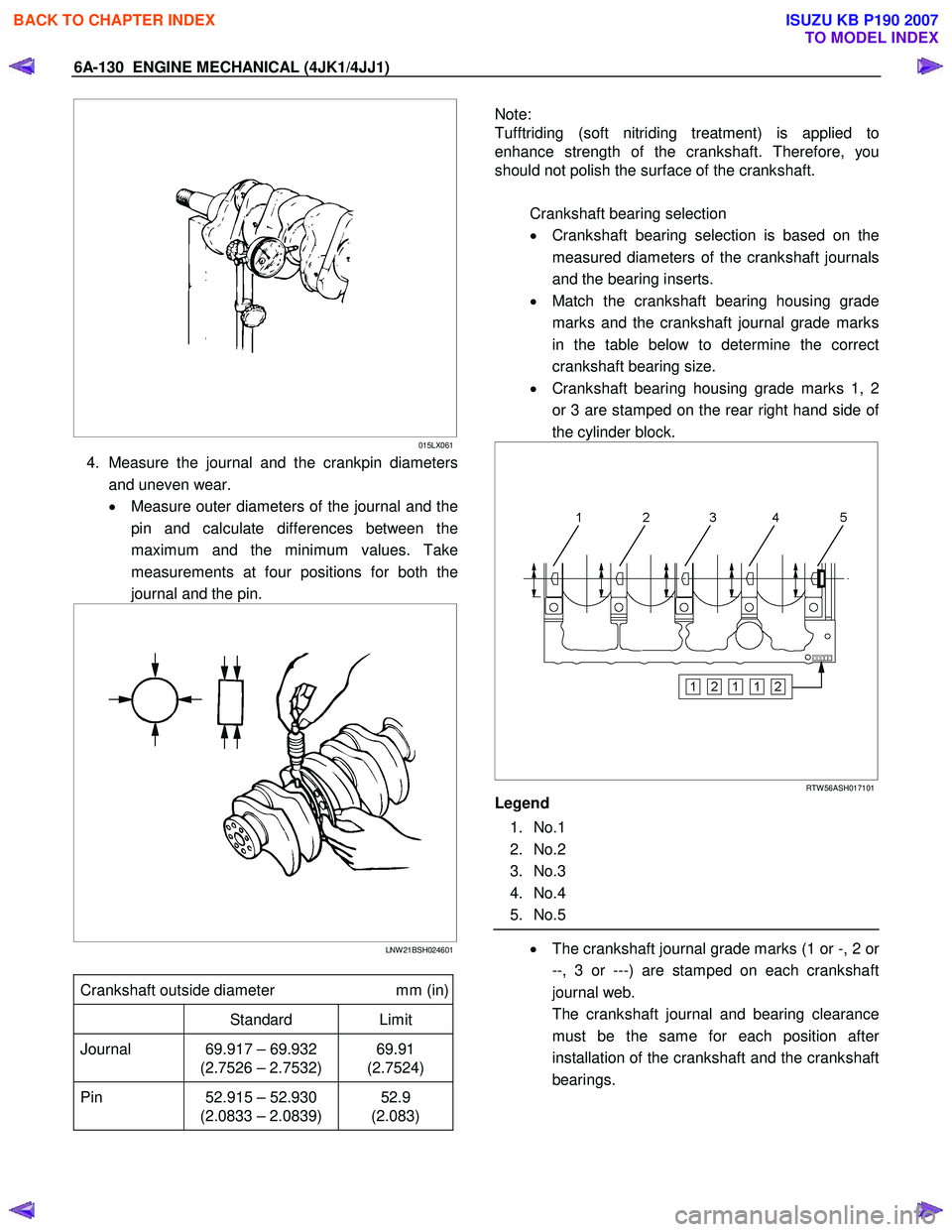
• Crankshaft bearing housing grade marks 1, 2
or 3 are stamped on the rear right hand side o
f
the cylinder block.
RTW 56ASH017101
Legend
1. No.1
2. No.2
3. No.3
4. No.4
5. No.5
• The crankshaft journal grade marks (1 or -, 2 or
--, 3 or ---) are stamped on each crankshaft
journal web.
The crankshaft journal and bearing clearance must be the same for each position afte
r
installation of the crankshaft and the crankshaft
bearings.
BACK TO CHAPTER INDEX
TO MODEL INDEX
ISUZU KB P190 2007
Page 1491 of 6020
ENGINE MECHANICAL (4JK1/4JJ1) 6A-131
4JK1
RTW 56ASH023901
Legend
1. No.1
2. No.2
3. No.3
4. No.4
5. No.5
NOTE:
The crankshaft journal mark No. 4 is stamped on
crankshaft No. 4 journal web front side or rear side. 4JJ1
RTW 56ASH017201
Legend
1. No.1
2. No.2
3. No.3
4. No.4
5. No.5
Note:
Be careful about difference in the shape of the bearings
when installing them.
RTW 56ASH017301
Legend
1. Lot No.
2. Size Code
BACK TO CHAPTER INDEX
TO MODEL INDEX
ISUZU KB P190 2007
Page 1492 of 6020
6A-132 ENGINE MECHANICAL (4JK1/4JJ1)
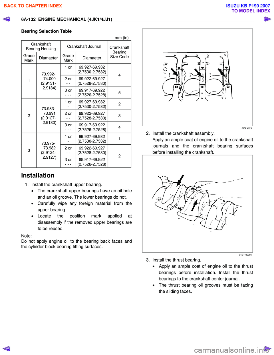
Bearing Selection Table
mm (in)
Crankshaft
Bearing Housing Crankshaft Journal
Grade
Mark Diamaeter
Grade
Mark Diamaeter Crankshaft
Bearing
Size Code
1 or - 69.927-69.932
(2.7530-2.7532)
2 or - - 69.922-69.927
(2.7528-2.7530) 4 1
73.992-
74.000
(2.9131-
2.9134) 3 or
- - - 69.917-69.922
(2.7526-2.7528) 5
1 or
- 69.927-69.932
(2.7530-2.7532) 2
2 or
- - 69.922-69.927
(2.7528-2.7530) 3 2 73.983-
73.991
(2.9127-
2.9130) 3 or
- - - 69.917-69.922
(2.7526-2.7528) 4
1 or
- 69.927-69.932
(2.7530-2.7532) 1
2 or
- - 69.922-69.927
(2.7528-2.7530) 3 73.975-
73.982
(2.9124-
2.9127) 3 or
- - - 69.917-69.922
(2.7526-2.7528) 2
Installation
1. Install the crankshaft upper bearing.
• The crankshaft upper bearings have an oil hole
and an oil groove. The lower bearings do not.
• Carefully wipe any foreign material from the
upper bearing.
• Locate the position mark applied at
disassembly if the removed upper bearings are
to be reused.
Note:
Do not apply engine oil to the bearing back faces and
the cylinder block bearing fitting surfaces.
015LX125
2. Install the crankshaft assembly.
Apply an ample coat of engine oil to the crankshaft
journals and the crankshaft bearing surfaces
before installing the crankshaft.
015R100004
3. Install the thrust bearing.
•
Apply an ample coat of engine oil to the thrust
bearings before installation. Install the thrust
bearings to the crankshaft center journal.
• The thrust bearing oil grooves must be facing
the sliding faces.
BACK TO CHAPTER INDEX
TO MODEL INDEX
ISUZU KB P190 2007
Page 1493 of 6020
ENGINE MECHANICAL (4JK1/4JJ1) 6A-133
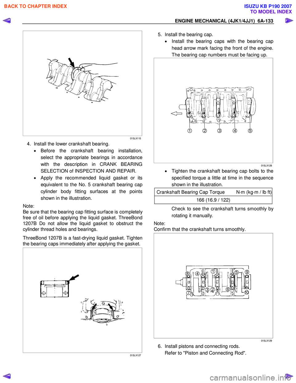
015LX115
4. Install the lower crankshaft bearing.
• Before the crankshaft bearing installation,
select the appropriate bearings in accordance
with the description in CRANK BEARING
SELECTION of INSPECTION AND REPAIR.
• Apply the recommended liquid gasket or its
equivalent to the No. 5 crankshaft bearing cap
cylinder body fitting surfaces at the points
shown in the illustration.
Note:
Be sure that the bearing cap fitting surface is completel
y
free of oil before applying the liquid gasket. ThreeBond
1207B Do not allow the liquid gasket to obstruct the
cylinder thread holes and bearings.
ThreeBond 1207B is a fast-drying liquid gasket. Tighten
the bearing caps immediately after applying the gasket.
015LX127
5. Install the bearing cap.
• Install the bearing caps with the bearing cap
head arrow mark facing the front of the engine.
The bearing cap numbers must be facing up.
015LX128
• Tighten the crankshaft bearing cap bolts to the
specified torque a little at time in the sequence
shown in the illustration.
Crankshaft Bearing Cap Torque N ⋅m (kg ⋅m / lb ft)
166 (16.9 / 122)
Check to see the crankshaft turns smoothly by
rotating it manually.
Note:
Confirm that the crankshaft turns smoothly.
015LX129
6. Install pistons and connecting rods.
Refer to "Piston and Connecting Rod".
BACK TO CHAPTER INDEX
TO MODEL INDEX
ISUZU KB P190 2007