Page 1502 of 6020
6A-142 ENGINE MECHANICAL (4JK1/4JJ1)
Engine oil leakage
• In the lift up condition, confirm that there are no
leaks from the cylinder head cover and oil pan.
BACK TO CHAPTER INDEX
TO MODEL INDEX
ISUZU KB P190 2007
Page 1503 of 6020
ENGINE MECHANICAL (4JK1/4JJ1) 6A-143
Oil Filter Cartridge
Components
RTW 56ASF000101
Legend 1. Oil Filter Cartridge
Removal
1. Place a tray under the oil filter cartridge.
2. Remove the oil filter cartridge using the oil filte
r
wrench.
Special tool
Oil filter wrench: 5-8840-0203-0 (1)
RTW 56ASH012501
Installation
1. Install the oil filter cartridge.
•
Apply grease or engine oil to the seal in the
cartridge and install it using the oil filter wrench.
• Tighten the cartridge using the specified torque.
Tightening torque: 20 N·m (2.0 kg·m / 14 lb ft) Or
After it comes in contact with the oil seal,
tighten it through an additional turn of 1 and
1/4.
Special tool
Oil filter wrench: 5-8840-0203-0
BACK TO CHAPTER INDEX
TO MODEL INDEX
ISUZU KB P190 2007
Page 1504 of 6020
6A-144 ENGINE MECHANICAL (4JK1/4JJ1)
Special Tools
ILLUSTRATION PART NO.
PART NAME
5-8840-0203-0
Oil filter wrench
BACK TO CHAPTER INDEX
TO MODEL INDEX
ISUZU KB P190 2007
Page 1505 of 6020
ENGINE MECHANICAL (4JK1/4JJ1) 6A-145
Oil Filter Assembly and Oil Cooler
Components
RTW 56AMF000401
Legend
1. Exhaust Manifold
2. Generator Bracket
3. Generator Adjustment Bracket 4. W ater Bypass Pipe
5. W ater Intake Pipe
6. Oil Filter Assembly and Oil Cooler
Removal
1. Remove the exhaust manifold.
Refer to removal procedure for "Turbocharger and Exhaust Manifold" in this manual.
2. Remove the generator.
Refer to removal procedure for generator in this manual.
3. Remove the adjustment bracket of generator.
4. Remove the bracket of generator.
5. Remove the water bypass pipe (1).
RTW 56ASH008401
BACK TO CHAPTER INDEX
TO MODEL INDEX
ISUZU KB P190 2007
Page 1506 of 6020
6A-146 ENGINE MECHANICAL (4JK1/4JJ1)
6. Remove the water intake pipe.
RTW 56ASH012601
Legend
1. W ater Intake Pipe
2. Bracket
3. Bracket
4. Bolt
7. Remove the oil cooler.
RTW 66ASH009101
Disassembly
1. Remove the element mounting nut (1).
RTW 56ASH012901
2. Remove the element (1).
3. Remove the gasket (2).
RTW 56ASH013001
BACK TO CHAPTER INDEX
TO MODEL INDEX
ISUZU KB P190 2007
Page 1507 of 6020
ENGINE MECHANICAL (4JK1/4JJ1) 6A-147
Reassembly
1. Install the gasket on the element.
2. Install the element.
3. Tighten the element fixing nut using the specified torque.
Tightening torque: 25 N ⋅
⋅⋅
⋅
m (2.5 kg ⋅
⋅⋅
⋅
m / 18 lb ft)
Installation
1. Install the oil filter and cooler.
• Install the O-ring on the oil filter and cooler,
apply grease.
•
Apply the liquid gasket and mount within 5
minutes. Apply liquid gasket (ThreeBond TB-
1207C or equivalent) to the flange surface
groove (cylinder block). Bead diameter must
be between 2 and 3 mm (0.079 and 0.118 in).
Refer to the illustration for the offset position
(no more than 1 mm (0.004 in)).
RTW 56ASH013101
Legend
1. Liquid Gasket
2. O-ring
• Align the oil filter and cooler holes with the
cylinder block studs. Install the oil cooler to the
cylinder clock.
BACK TO CHAPTER INDEX
TO MODEL INDEX
ISUZU KB P190 2007
Page 1508 of 6020

6A-148 ENGINE MECHANICAL (4JK1/4JJ1)
RTW 56ASH013201
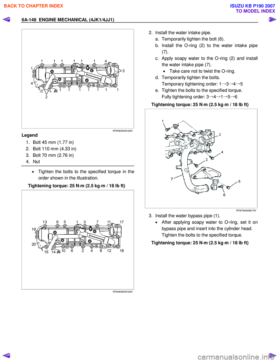
Legend
1. Bolt 45 mm (1.77 in)
2. Bolt 110 mm (4.33 in)
3. Bolt 70 mm (2.76 in)
4. Nut
• Tighten the bolts to the specified torque in the
order shown in the illustration.
Tightening torque: 25 N ⋅
⋅⋅
⋅
m (2.5 kg ⋅
⋅⋅
⋅
m / 18 lb ft)
RTW 56ASH013301
2. Install the water intake pipe.
a. Temporarily tighten the bolt (6).
b. Install the O-ring (2) to the water intake pipe (7).
c. Apply soapy water to the O-ring (2) and install the water intake pipe (7). • Take care not to twist the O-ring.
d. Temporarily tighten the bolts.
Temporary tightening order: 1 →3→ 4→ 5
e. Tighten the bolts to the specified torque.
Fully tightening order: 3 →4→ 1→ 5→ 6
Tightening torque: 25 N ⋅
⋅⋅
⋅
m (2.5 kg ⋅
⋅⋅
⋅
m / 18 lb ft)
RTW 76ASH001701
3. Install the water bypass pipe (1).
• After applying soapy water to O-ring, set it on
bypass pipe and insert into the cylinder head.
Tighten the bolts to the specified torque.
Tightening torque: 25 N ⋅
⋅⋅
⋅
m (2.5 kg ⋅
⋅⋅
⋅
m / 18 lb ft)
BACK TO CHAPTER INDEX
TO MODEL INDEX
ISUZU KB P190 2007
Page 1509 of 6020
ENGINE MECHANICAL (4JK1/4JJ1) 6A-149
RTW 56ASH008401
4. Install the bracket of generator.
Tighten the bolts to the specified torque.
Tightening torque: 51 N ⋅
⋅⋅
⋅
m (5.2 kg ⋅
⋅⋅
⋅
m / 38 lb ft)
5. Install the adjustment bracket of generator.
Tighten the bolts to the specified torque.
Tightening torque: 25 N ⋅
⋅⋅
⋅
m (2.5 kg ⋅
⋅⋅
⋅
m / 18 lb ft)
6. Install the generator.
Refer to Installation procedure for generator in this manual.
7. Install the exhaust manifold.
Refer to Installation procedure for turbocharge
r
and exhaust manifold in this manual.
BACK TO CHAPTER INDEX
TO MODEL INDEX
ISUZU KB P190 2007