Page 1470 of 6020
6A-110 ENGINE MECHANICAL (4JK1/4JJ1)
Torque Specifications
RTW 56AMF001801
Special Tools
ILLUSTRATION PART NO.
PART NAME
5-8840-9018-0
Piston ring compressor
5-8840-0266-0
Angle gauge
BACK TO CHAPTER INDEX
TO MODEL INDEX
ISUZU KB P190 2007
Page 1471 of 6020
ENGINE MECHANICAL (4JK1/4JJ1) 6A-111
Flywheel
Components
RTW 56ALF001701
Legend 1. Flywheel Assembly and Pilot Bearing
2. Driven Plate
3. Pressure Plate Assembly 4. Release Bearing
5. Shift Fork
6. Transmission Assembly
Removal
1. Remove the transmission assembly.
Refer to "transmission assembly removal and installation".
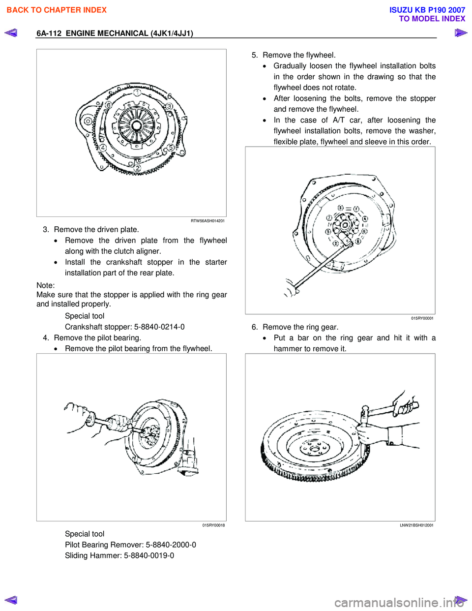
2. Remove the clutch pressure plate.
• Remove the pressure plate installation bolts in
the order shown in the drawing.
• Remove the pressure plate from the flywheel.
BACK TO CHAPTER INDEX
TO MODEL INDEX
ISUZU KB P190 2007
Page 1472 of 6020

6A-112 ENGINE MECHANICAL (4JK1/4JJ1)
RTW 56ASH014201
3. Remove the driven plate.
• Remove the driven plate from the flywheel
along with the clutch aligner.
• Install the crankshaft stopper in the starte
r
installation part of the rear plate.
Note:
Make sure that the stopper is applied with the ring gea
r
and installed properly.
Special tool
Crankshaft stopper: 5-8840-0214-0
4. Remove the pilot bearing. • Remove the pilot bearing from the flywheel.
015RY00018
Special tool
Pilot Bearing Remover: 5-8840-2000-0
Sliding Hammer: 5-8840-0019-0
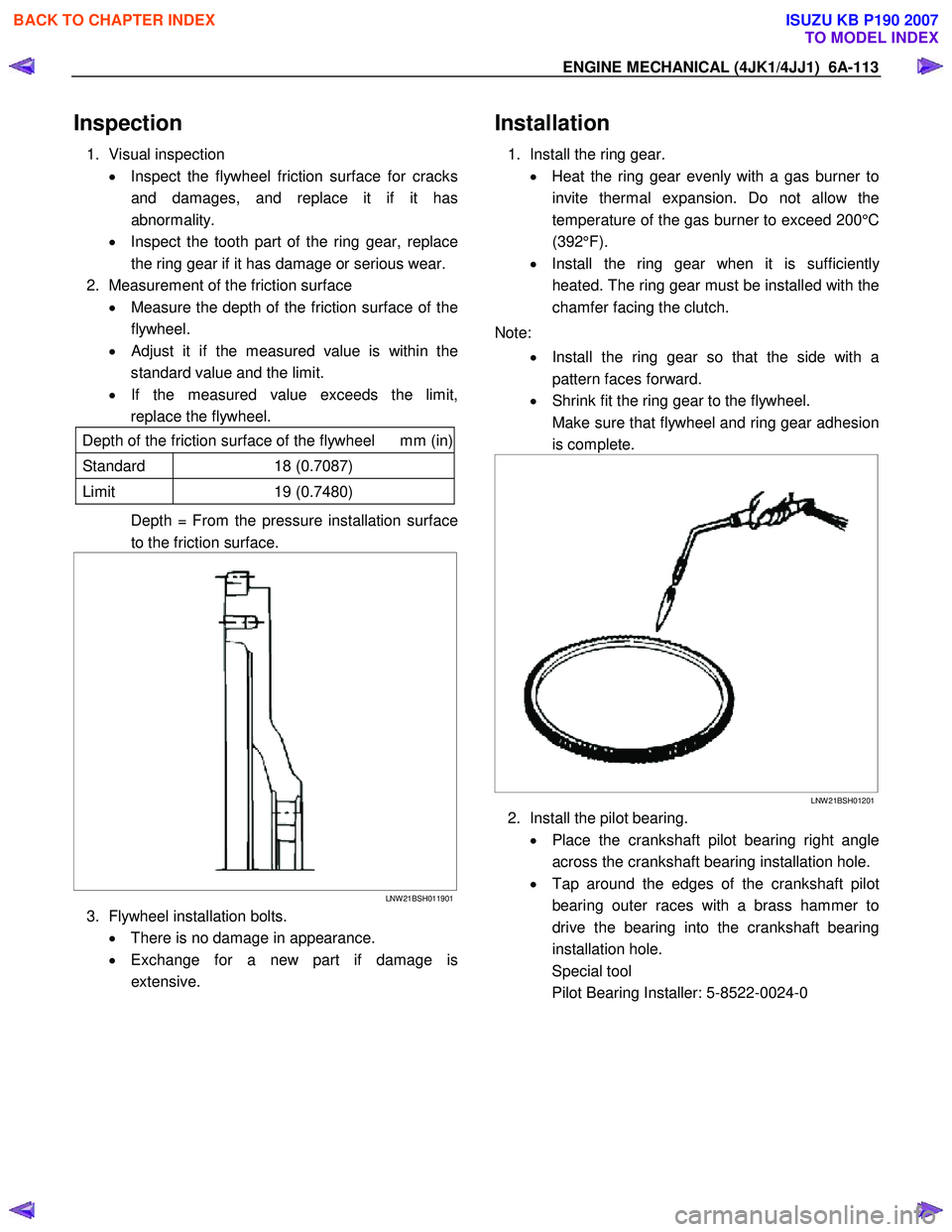
5. Remove the flywheel.
• Gradually loosen the flywheel installation bolts
in the order shown in the drawing so that the
flywheel does not rotate.
•
After loosening the bolts, remove the stopper
and remove the flywheel.
• In the case of A/T car, after loosening the
flywheel installation bolts, remove the washer,
flexible plate, flywheel and sleeve in this order.
015RY00001
6. Remove the ring gear.
• Put a bar on the ring gear and hit it with a
hammer to remove it.
LNW 21BSH012001
BACK TO CHAPTER INDEX
TO MODEL INDEX
ISUZU KB P190 2007
Page 1473 of 6020

ENGINE MECHANICAL (4JK1/4JJ1) 6A-113
Inspection
1. Visual inspection
• Inspect the flywheel friction surface for cracks
and damages, and replace it if it has
abnormality.
• Inspect the tooth part of the ring gear, replace
the ring gear if it has damage or serious wear.
2. Measurement of the friction surface • Measure the depth of the friction surface of the
flywheel.
•
Adjust it if the measured value is within the
standard value and the limit.
• If the measured value exceeds the limit,
replace the flywheel.
Depth of the friction surface of the flywheel mm (in)
Standard 18 (0.7087)
Limit 19 (0.7480)
Depth = From the pressure installation surface
to the friction surface.
LNW 21BSH011901
3. Flywheel installation bolts.
• There is no damage in appearance.
• Exchange for a new part if damage is
extensive.
Installation
1. Install the ring gear.
• Heat the ring gear evenly with a gas burner to
invite thermal expansion. Do not allow the
temperature of the gas burner to exceed 200°C
(392°F).
• Install the ring gear when it is sufficientl
y
heated. The ring gear must be installed with the
chamfer facing the clutch.
Note: • Install the ring gear so that the side with a
pattern faces forward.
• Shrink fit the ring gear to the flywheel.
Make sure that flywheel and ring gear adhesion is complete.
LNW 21BSH01201
2. Install the pilot bearing.
• Place the crankshaft pilot bearing right angle
across the crankshaft bearing installation hole.
• Tap around the edges of the crankshaft pilot
bearing outer races with a brass hammer to
drive the bearing into the crankshaft bearing
installation hole.
Special tool
Pilot Bearing Installer: 5-8522-0024-0
BACK TO CHAPTER INDEX
TO MODEL INDEX
ISUZU KB P190 2007
Page 1474 of 6020

6A-114 ENGINE MECHANICAL (4JK1/4JJ1)
015RY00010
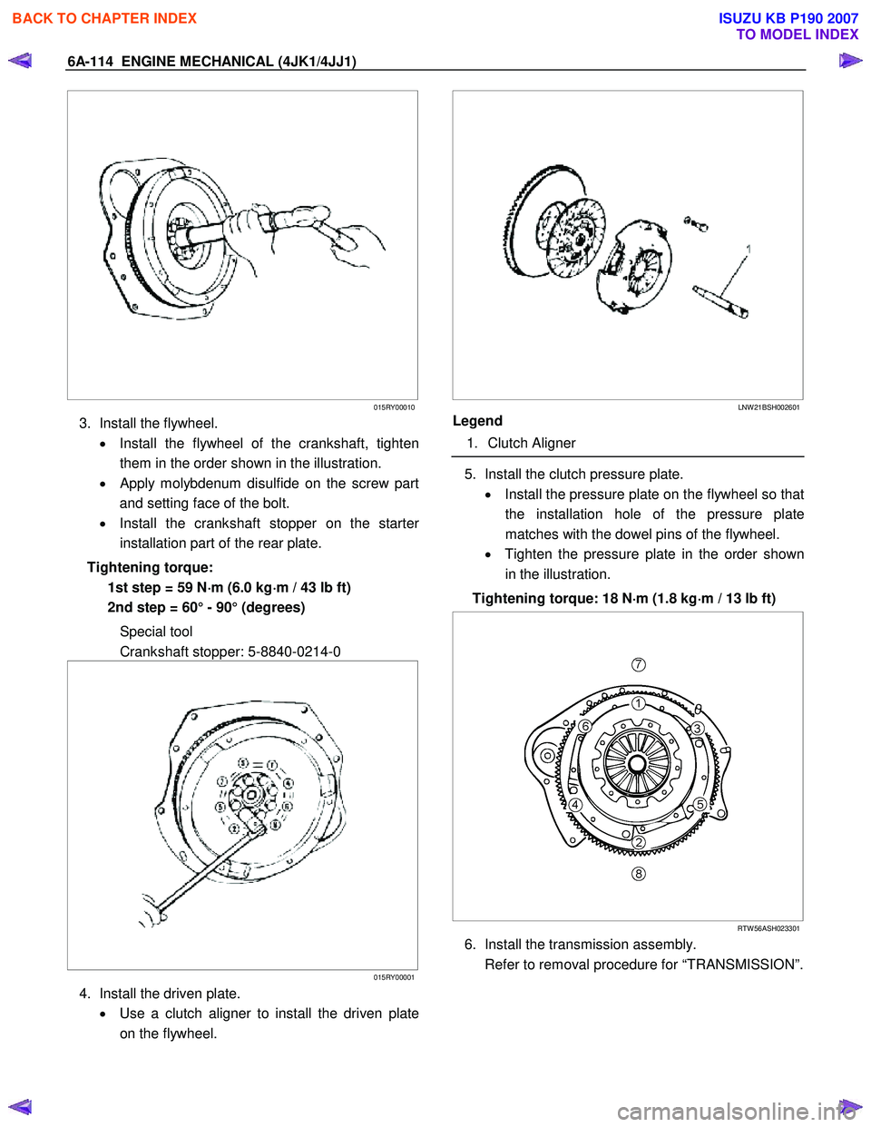
3. Install the flywheel.
• Install the flywheel of the crankshaft, tighten
them in the order shown in the illustration.
•
Apply molybdenum disulfide on the screw part
and setting face of the bolt.
• Install the crankshaft stopper on the starte
r
installation part of the rear plate.
Tightening torque: 1st step = 59 N ⋅
⋅⋅
⋅
m (6.0 kg ⋅
⋅⋅
⋅
m / 43 lb ft)
2nd step = 60° - 90° (degrees)
Special tool
Crankshaft stopper: 5-8840-0214-0
015RY00001
4. Install the driven plate.
• Use a clutch aligner to install the driven plate
on the flywheel.
LNW 21BSH002601
Legend
1. Clutch Aligner
5. Install the clutch pressure plate.
• Install the pressure plate on the flywheel so that
the installation hole of the pressure plate
matches with the dowel pins of the flywheel.
• Tighten the pressure plate in the order shown
in the illustration.
Tightening torque: 18 N ⋅
⋅⋅
⋅
m (1.8 kg ⋅
⋅⋅
⋅
m / 13 lb ft)
RTW 56ASH023301
6. Install the transmission assembly.
Refer to removal procedure for “TRANSMISSION”.
BACK TO CHAPTER INDEX
TO MODEL INDEX
ISUZU KB P190 2007
Page 1475 of 6020
ENGINE MECHANICAL (4JK1/4JJ1) 6A-115
Torque Specifications
Special Tools
ILLUSTRATION PART NO.
PART NAME
ILLUSTRATION PART NO.
PART NAME
5-8840-0214-0
Crankshaft stopper
5-8522-0024-0
Pilot Bearing Installer
5-8840-2000-0
Pilot Bearing Remover
5-8840-0019-0
Sliding Hammer
BACK TO CHAPTER INDEX
TO MODEL INDEX
ISUZU KB P190 2007
Page 1476 of 6020
6A-116 ENGINE MECHANICAL (4JK1/4JJ1)
Gear Case Assembly
Components
RTW 76ALF000601
Legend 1. Adjust Plate
2. Generator 3. Gasket
4. Gear Case Assembly
BACK TO CHAPTER INDEX
TO MODEL INDEX
ISUZU KB P190 2007
Page 1477 of 6020

ENGINE MECHANICAL (4JK1/4JJ1) 6A-117
Removal
1. Remove the engine assembly.
Refer to removal procedure for “Engine Assembly” in this manual.
2. Remove the cylinder head.
Refer to removal procedure for “Cylinder Head” in this manual.
3. Remove the adjustment bracket of generator.
4. Remove the vacuum pump and pipe.
Refer to removal procedure for “Brake” in this manual.
5. Remove the power steering pump.
Refer to removal procedure for “Power Steering” in this manual.
6. Remove the water pump.
Refer to removal procedure for “W ater Pump” in this manual.
7. Remove the fuel supply pump.
Refer to removal procedure for “Fuel Suppl
y
Pump” in this manual.
8. Remove the crankshaft pulley.
Refer to removal procedure for “Crankshaft Front Oil Seal” in this manual.
9. Remove the gear case cover.
Refer to removal procedure for “Gear Case Cover” in this manual.
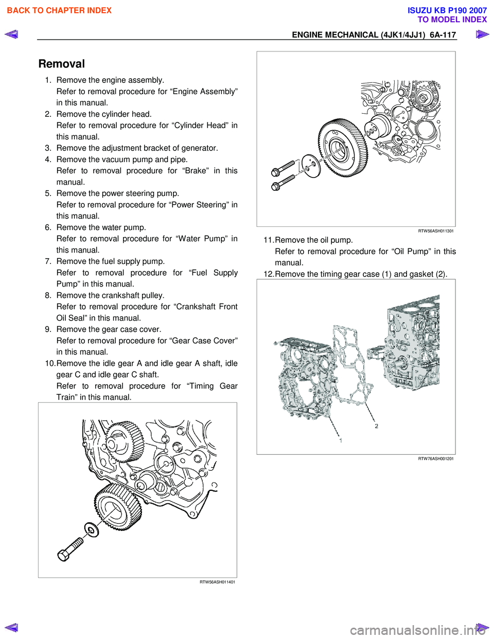
10. Remove the idle gear A and idle gear A shaft, idle gear C and idle gear C shaft.
Refer to removal procedure for “Timing Gea
r
Train” in this manual.
RTW 56ASH011401
RTW 56ASH011301
11. Remove the oil pump.
Refer to removal procedure for “Oil Pump” in this manual.
12. Remove the timing gear case (1) and gasket (2).
RTW 76ASH001201
BACK TO CHAPTER INDEX
TO MODEL INDEX
ISUZU KB P190 2007