2007 ISUZU KB P190 stop start
[x] Cancel search: stop startPage 2279 of 6020
ENGINE DRIVEABILITY AND EMISSIONS 6E–109
• The fuel injector(s).
4. Fuel pressure that drops off during acceleration, cruise, or hard cornering may case a lean condition.
A lean condition can cause a loss of power, surging,
or misfire. A lean condition can be diagnosed using a
Tech 2 Scan Tool.
Following are applicable to the vehicle with
closed Loop System:
If an extremely lean condition occurs, the oxygen
sensor(s) will stop toggling. The oxygen sensor
output voltage(s) will drop below 500 mV. Also, the
fuel injector pulse width will increase.
Important: Make sure the fuel system is not
operating in the “Fuel Cut-Off Mode.”
When the engine is at idle, the manifold pressure is
low (high vacuum). This low pressure (high vacuum)
is applied to the fuel pressure regulator diaphragm.
The low pressure (high vacuum) will offset the
pressure being applied to the fuel pressure regulator
diaphragm by the spring inside the fuel pressure
regulator. When this happens, the result is lower fuel
pressure. The fuel pressure at idle will vary slightly
as the barometric pressure changes, but the fuel
pressure at idle should always be less than the fuel
pressure noted in step 2 with the engine OFF.
16.Check the spark plug associated with a particular
fuel injector for fouling or saturation in order to
determine if that particular fuel injector is leaking. If
checking the spark plug associated with a particular
fuel injector for fouling or saturation does not
determine that a particular fuel injector is leaking,
use the following procedure:
• Remove the fuel rail, but leave the fuel lines and injectors connected to the fuel rail. Refer to Fuel
Rail Assembly in On-Vehicle Service .
• Lift the fuel rail just enough to leave the fuel injector nozzles in the fuel injector ports.
Caution: In order to reduce the risk of fire and
personal injury that may result from fuel
spraying on the engine, verify that the fuel rail is
positioned over the fuel injector ports and verify
that the fuel injector retaining clips are intact.
• Pressurize the fuel system by connecting a 20 amp fused jumper between B+ and the fuel
pump relay connector.
• Visually and physically inspect the fuel injector nozzles for leaks.
17.A rich condition may result from the fuel pressure being above 376 kPa (55 psi). A rich condition may
cause a 45 to set. Driveability conditions associated with rich conditions can include hard starting
(followed by black smoke) and a strong sulfur smell
in the exhaust.
20.This test determines if the high fuel pressure is due to a restricted fuel return line or if the high fuel
pressure is due to a faulty fuel pressure regulator.
21.A lean condition may result from fuel pressure below 333 kPa (48 psi). A lean condition may cause a 44 to
set. Driveability conditions associated with lean
conditions can include hard starting (when the
engine is cold), hesitation, poor driveability, lack of
power, surging, and misfiring.
22.Restricting the fuel return line causes the fuel pressure to rise above the regulated fuel pressure.
Command the fuel pump ON with the scan tool. The
fuel pressure should rise above 376 kPa (55 psi) as
the fuel return line becomes partially closed.
NOTE: Do not allow the fuel pressure to exceed 414
kPa (60 psi). Fuel pressure in excess of 414 kPa (60
psi) may damage the fuel pressure regulator. Caution: To reduce the risk of fire and personal
injury:
• It is necessary to relieve fuel system pressure before connecting a fuel pressure gauge.
Refer to Fuel Pressure Relief Procedure,
below.
• A small amount of fuel may be released when disconnecting the fuel lines. Cover fuel line
fittings with a shop towel before
disconnecting, to catch any fuel that may leak
out. Place the towel in an approved container
when the disconnect is completed.
Fuel Pressure Relief Procedure
1. Remove the fuel cap.
2. Located on the intake manifold which is at the top right part of the engine.
3. Start the engine and allow it to stall.
4. Crank the engine for an additional 3 seconds.
Fuel Pressure Gauge Installation
1. Remove the fuel pressure fitting cap.
2. Install fuel pressure gauge 5-8840-0378-0 to the fuel feed line located on the upper right side of the
engine.
3. Reinstall the fuel pump relay.
BACK TO CHAPTER INDEX
TO MODEL INDEX
ISUZU KB P190 2007
Page 2280 of 6020
6E–110 ENGINE DRIVEABILITY AND EMISSIONS
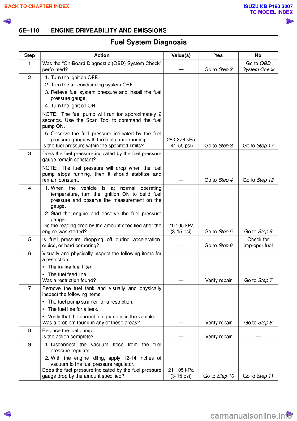
Fuel System Diagnosis
StepAction Value(s) Yes No
1 Was the “On-Board Diagnostic (OBD) System Check” performed? — Go to Step 2Go to
OBD
System Check
2 1. Turn the ignition OFF. 2. Turn the air conditioning system OFF.
3. Relieve fuel system pressure and install the fuel pressure gauge.
4. Turn the ignition ON.
NOTE: The fuel pump will run for approximately 2
seconds. Use the Scan Tool to command the fuel
pump ON.
5. Observe the fuel pressure indicated by the fuel pressure gauge with the fuel pump running.
Is the fuel pressure within the specified limits? 283-376 kPa
(41-55 psi) Go to Step 3Go to Step 17
3 Does the fuel pressure indicated by the fuel pressure gauge remain constant?
NOTE: The fuel pressure will drop when the fuel
pump stops running, then it should stabilize and
remain constant. — Go to Step 4Go to Step 12
4 1. When the vehicle is at normal operating temperature, turn the ignition ON to build fuel
pressure and observe the measurement on the
gauge.
2. Start the engine and observe the fuel pressure gauge.
Did the reading drop by the amount specified after the
engine was started? 21-105 kPa
(3-15 psi) Go to Step 5Go to Step 9
5 Is fuel pressure dropping off during acceleration, cruise, or hard cornering? — Go to Step 6Check for
improper fuel
6 Visually and physically inspect the following items for a restriction:
• The in-line fuel filter.
• The fuel feed line.
Was a restriction found? — Verify repair Go to Step 7
7 Remove the fuel tank and visually and physically inspect the following items:
• The fuel pump strainer for a restriction.
• The fuel line for a leak.
• Verify that the correct fuel pump is in the vehicle.
Was a problem found in any of these areas? — Verify repair Go to Step 8
8 Replace the fuel pump. Is the action complete? — Verify repair —
9 1. Disconnect the vacuum hose from the fuel pressure regulator.
2. With the engine idling, apply 12-14 inches of vacuum to the fuel pressure regulator.
Does the fuel pressure indicated by the fuel pressure
gauge drop by the amount specified? 21-105 kPa
(3-15 psi) Go to Step 10Go to Step 11
BACK TO CHAPTER INDEX
TO MODEL INDEX
ISUZU KB P190 2007
Page 2441 of 6020
ENGINE DRIVEABILITY AND EMISSIONS 6E–271
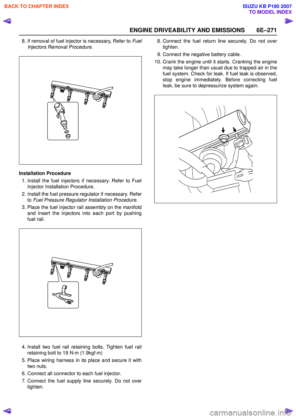
8. If removal of fuel injector is necessary, Refer to Fuel
Injectors Removal Procedure .
Installation Procedure 1. Install the fuel injectors if necessary. Refer to Fuel Injector Installation Procedure.
2. Install the fuel pressure regulator if necessary. Refer to Fuel Pressure Regulator Installation Procedure .
3. Place the fuel injector rail assembly on the manifold and insert the injectors into each port by pushing
fuel rail.
4. Install two fuel rail retaining bolts. Tighten fuel rail retaining bolt to 19 N·m (1.9kgf·m)
5. Place wiring harness in its place and secure it with two nuts.
6. Connect all connector to each fuel injector.
7. Connect the fuel supply line securely. Do not over tighten. 8. Connect the fuel return line securely. Do not over
tighten.
9. Connect the negative battery cable.
10. Crank the engine until it starts. Cranking the engine may take longer than usual due to trapped air in the
fuel system. Check for leak. If fuel leak is observed,
stop engine immediately. Before correcting fuel
leak, be sure to depressurize system again.
BACK TO CHAPTER INDEX
TO MODEL INDEX
ISUZU KB P190 2007
Page 2521 of 6020
Engine Mechanical – V6 Page 6A1–42
2.19 Engine Oil Pressure Diagnosis
If the engine oil pressure is below the specified value, inspect the engine and components for the following:
• loose oil filter adaptor bolts,
• faulty oil filter adaptor seals,
• worn or faulty oil pump,
• loose oil pump bolts,
• loose, blocked or damaged oil pump suction pipe,
• faulty oil pump suction pipe seal,
• faulty oil pump pressure relief valve,
• faulty or incorrectly installed oil gallery plugs,
• excessive bearing clearance in one of the following:
• connecting rods big end/s,
• crankshaft main journal/s,
• camshaft/s,
• camshaft sprocket/s, and
• cracked, porous or restricted oil galleries, or broken lash adjuster/s.
2.20 Accessory Drive Belt Diagnosis
Tension Check
NOTE
An accessory drive belt that squeaks when the
engine is started or stopped is considered normal
and has no effect on drive belt durability.
1 Start the engine and switch off the air-conditioning system. Allow engine to run until normal operating temperature has been reached.
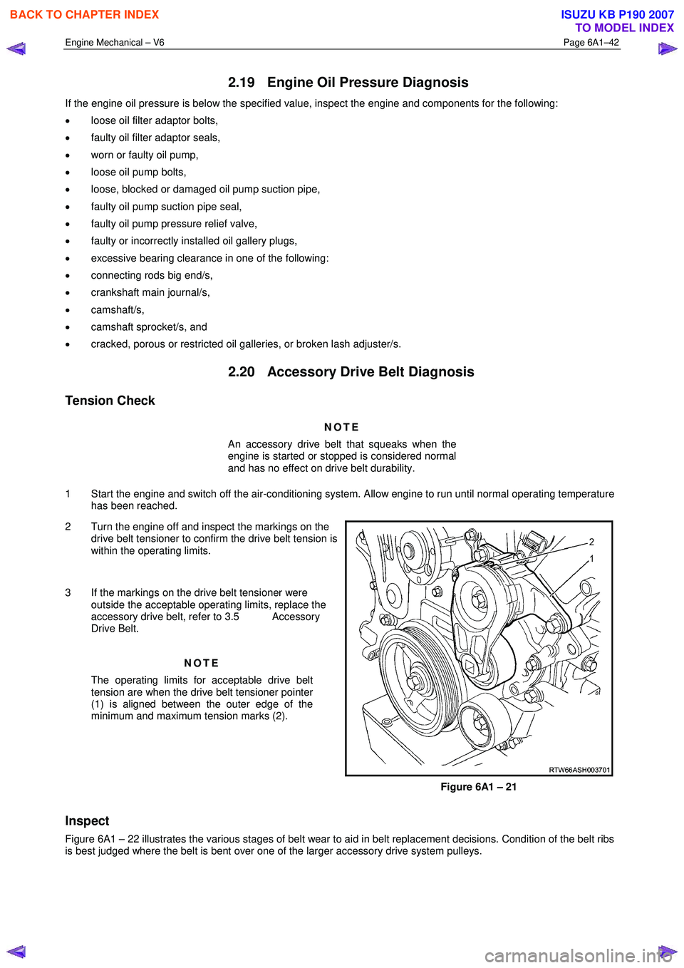
2 Turn the engine off and inspect the markings on the drive belt tensioner to confirm the drive belt tension is
within the operating limits.
3 If the markings on the drive belt tensioner were outside the acceptable operating limits, replace the
accessory drive belt, refer to 3.5 Accessory
Drive Belt.
NOTE
The operating limits for acceptable drive belt
tension are when the drive belt tensioner pointer
(1) is aligned between the outer edge of the
minimum and maximum tension marks (2).
Figure 6A1 – 21
Inspect
Figure 6A1 – 22 illustrates the various stages of belt wear to aid in belt replacement decisions. Condition of the belt ribs
is best judged where the belt is bent over one of the larger accessory drive system pulleys.
BACK TO CHAPTER INDEX
TO MODEL INDEX
ISUZU KB P190 2007
Page 2534 of 6020
Engine Mechanical – V6 Page 6A1–55
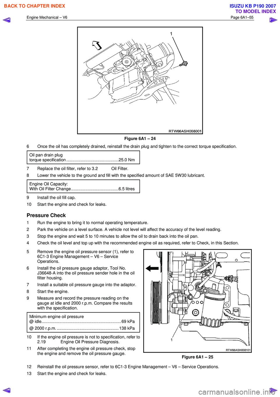
Figure 6A1 – 24
6 Once the oil has completely drained, reinstall the drain plug and tighten to the correct torque specification.
Oil pan drain plug
torque specification ............................................25.0 Nm
7 Replace the oil filter, refer to 3.2 Oil Filter.
8 Lower the vehicle to the ground and fill with the specified amount of SAE 5W 30 lubricant.
Engine Oil Capacity:
With Oil Filter Change ........................................6.5 litres
9 Install the oil fill cap.
10 Start the engine and check for leaks.
Pressure Check
1 Run the engine to bring it to normal operating temperature.
2 Park the vehicle on a level surface. A vehicle not level will affect the accuracy of the level reading.
3 Stop the engine and wait 5 to 10 minutes to allow the oil to drain back into the oil pan.
4 Check the oil level and top up with the recommended engine oil as required, refer to Check, in this Section.
5 Remove the engine oil pressure sensor (1), refer to 6C1-3 Engine Management – V6 – Service
Operations.
6 Install the oil pressure gauge adaptor, Tool No. J36648-A into the oil pressure sender hole in the oil
filter housing.
7 Install a suitable oil pressure gauge into the adaptor.
8 Start the engine.
9 Measure and record the pressure reading on the gauge at idle and 2000 r.p.m. Compare the results
with the specification.
Minimum engine oil pressure
@ idle................................................................... 69 kPa
@ 2000 r.p.m. .................................................... 138 kPa
10 If the engine oil pressure is not to specification, refer to 2.19 Engine Oil Pressure Diagnosis.
11 After completing the engine oil pressure check, stop the engine and remove the oil pressure gauge.
Figure 6A1 – 25
12 Reinstall the oil pressure sensor, refer to 6C1-3 Engine Management – V6 – Service Operations.
13 Start the engine and check for leaks.
BACK TO CHAPTER INDEX
TO MODEL INDEX
ISUZU KB P190 2007
Page 2563 of 6020
Engine Mechanical – V6 Page 6A1–84
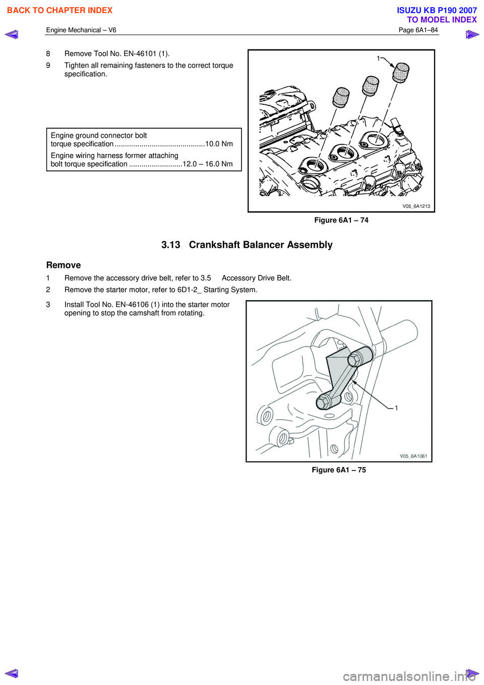
8 Remove Tool No. EN-46101 (1).
9 Tighten all remaining fasteners to the correct torque specification.
Engine ground connector bolt
torque specification ............................................10.0 Nm
Engine wiring harness former attaching
bolt torque specification ..........................12.0 – 16.0 Nm
Figure 6A1 – 74
3.13 Crankshaft Balancer Assembly
Remove
1 Remove the accessory drive belt, refer to 3.5 Accessory Drive Belt.
2 Remove the starter motor, refer to 6D1-2_ Starting System.
3 Install Tool No. EN-46106 (1) into the starter motor opening to stop the camshaft from rotating.
Figure 6A1 – 75
BACK TO CHAPTER INDEX
TO MODEL INDEX
ISUZU KB P190 2007
Page 2845 of 6020
Engine Mechanical – V6 Page 6A1–68
Page 6A1–68
Pressure Check
1 Run the engine to bring it to normal operating temperature.
2 Park the vehicle on a level surface. A vehicle not level will affect the accuracy of the level reading.
3 Stop the engine and wait 5 to 10 minutes to a llow the oil to drain back into the oil pan.
4 Check the oil level and top up with the recommended engine o il as required, refer to Check, in this Section.
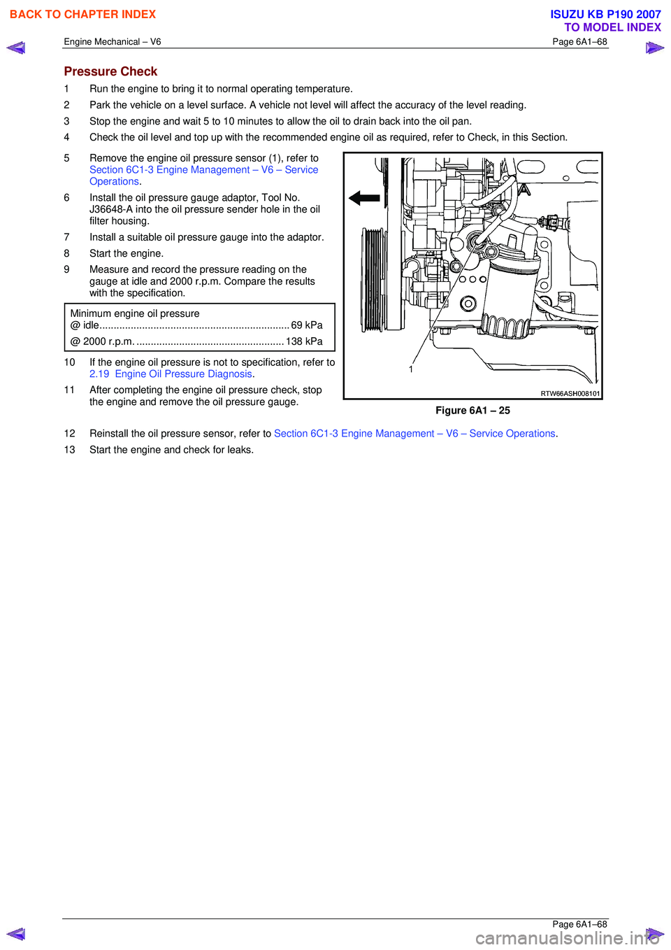
5 Remove the engine oil pressure sensor (1), refer to Section 6C1-3 Engine Management – V6 – Service
Operations .
6 Install the oil pressure gauge adaptor, Tool No. J36648-A into the oil pressure sender hole in the oil
filter housing.
7 Install a suitable oil pressure gauge into the adaptor.
8 Start the engine.
9 Measure and record the pressure reading on the gauge at idle and 2000 r.p.m. Compare the results
with the specification.
Minimum engine oil pressure
@ idle ................................................................... 69 kPa
@ 2000 r.p.m. .................................................... 138 kPa
10 If the engine oil pressure is not to specification, refer to
2.19 Engine Oil Pressure Diagnosis .
11 After completing the engine oil pressure check, stop the engine and remove the oil pressure gauge.
Figure 6A1 – 25
12 Reinstall the oil pressure sensor, refer to Section 6C1-3 Engine Management – V6 – Service Operations.
13 Start the engine and check for leaks.
BACK TO CHAPTER INDEX
TO MODEL INDEX
ISUZU KB P190 2007
Page 2877 of 6020
Engine Mechanical – V6 Page 6A1–100
Page 6A1–100
3.13 Crankshaft Balancer Assembly
Remove
1 Remove the accessory drive belt, refer to 3.5 Accessory Drive Belt.
2 Remove the starter motor, refer to Section 6D1-2 Starting System.
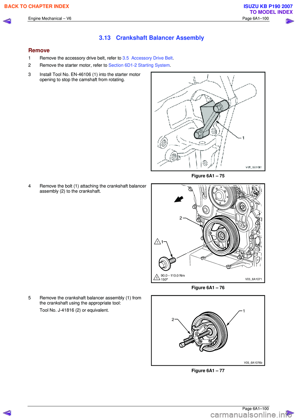
3 Install Tool No. EN-46106 (1) into the starter motor opening to stop the camshaft from rotating.
Figure 6A1 – 75
4 Remove the bolt (1) attaching the crankshaft balancer assembly (2) to the crankshaft.
Figure 6A1 – 76
5 Remove the crankshaft balancer assembly (1) from the crankshaft using the appropriate tool:
Tool No. J-41816 (2) or equivalent.
Figure 6A1 – 77
BACK TO CHAPTER INDEX
TO MODEL INDEX
ISUZU KB P190 2007