2007 ISUZU KB P190 stop start
[x] Cancel search: stop startPage 3188 of 6020
Engine Cooling – V6 Engine Page 6B1–53
NOTE
Should the spring clip or the O-ring seal in the
quick connect fitting be damaged during the line
removal process, then the complete fitting must
be replaced.
Reinstall
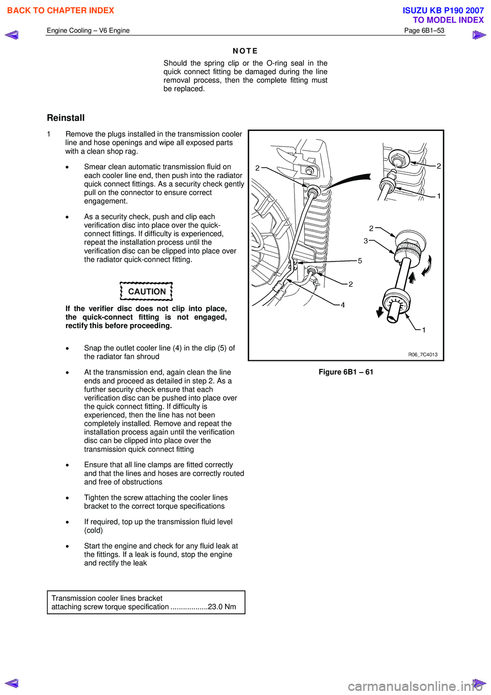
1 Remove the plugs installed in the transmission cooler line and hose openings and wipe all exposed parts
with a clean shop rag.
• Smear clean automatic transmission fluid on
each cooler line end, then push into the radiator
quick connect fittings. As a security check gently
pull on the connector to ensure correct
engagement.
• As a security check, push and clip each
verification disc into place over the quick-
connect fittings. If difficulty is experienced,
repeat the installation process until the
verification disc can be clipped into place over
the radiator quick-connect fitting.
If the verifier disc does not clip into place,
the quick-connect fitting is not engaged,
rectify this before proceeding.
• Snap the outlet cooler line (4) in the clip (5) of
the radiator fan shroud
• At the transmission end, again clean the line
ends and proceed as detailed in step 2. As a
further security check ensure that each
verification disc can be pushed into place over
the quick connect fitting. If difficulty is
experienced, then the line has not been
completely installed. Remove and repeat the
installation process again until the verification
disc can be clipped into place over the
transmission quick connect fitting
• Ensure that all line clamps are fitted correctly
and that the lines and hoses are correctly routed
and free of obstructions
• Tighten the screw attaching the cooler lines
bracket to the correct torque specifications
• If required, top up the transmission fluid level
(cold)
• Start the engine and check for any fluid leak at
the fittings. If a leak is found, stop the engine
and rectify the leak
Figure 6B1 – 61
Transmission cooler lines bracket
attaching screw torque specification ..................23.0 Nm
BACK TO CHAPTER INDEX
TO MODEL INDEX
ISUZU KB P190 2007
Page 3213 of 6020
Fuel System – V6 Page 6C – 11
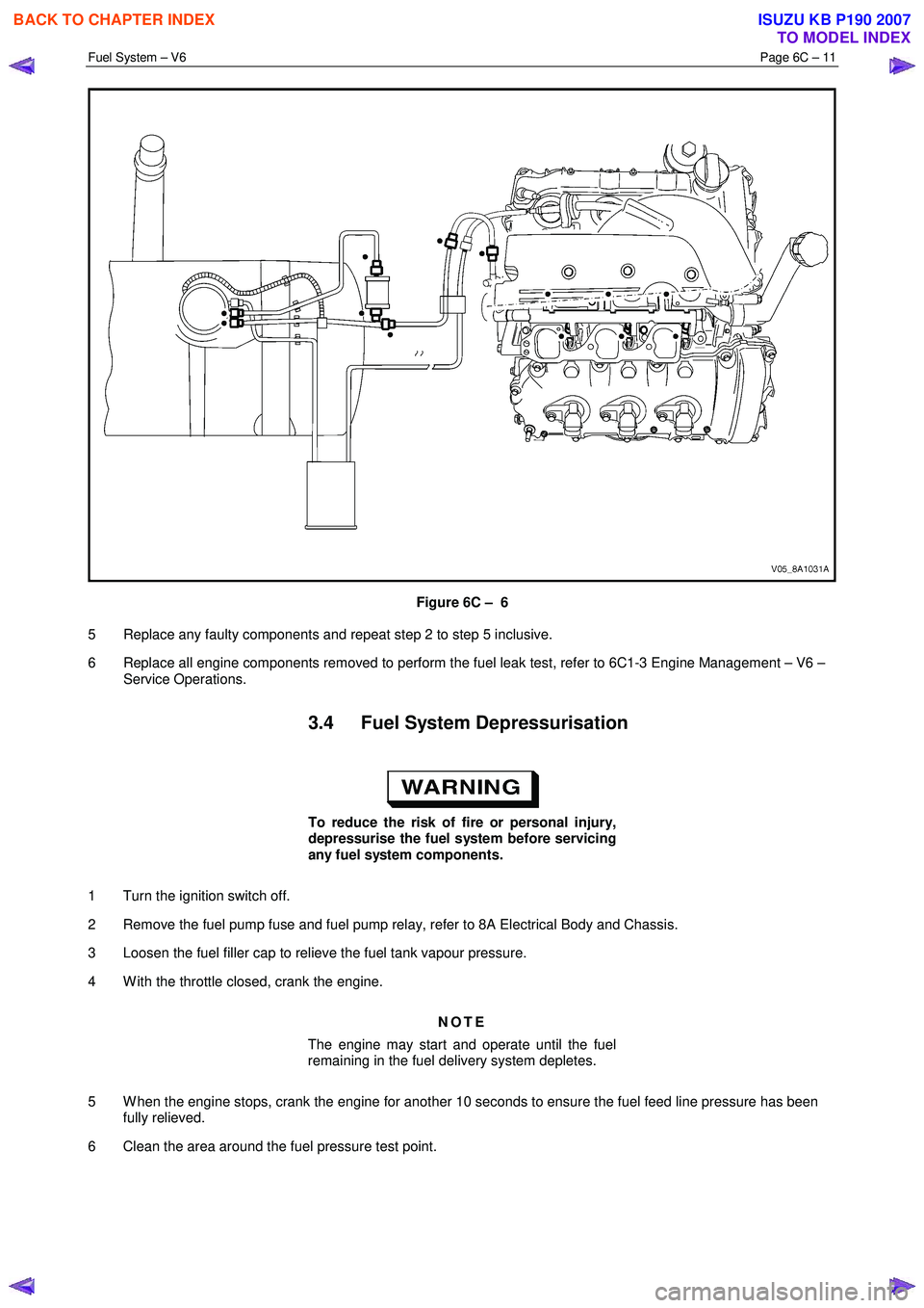
Figure 6C – 6
5 Replace any faulty components and repeat step 2 to step 5 inclusive.
6 Replace all engine components removed to perform the fuel leak test, refer to 6C1-3 Engine Management – V6 – Service Operations.
3.4 Fuel System Depressurisation
To reduce the risk of fire or personal injury,
depressurise the fuel system before servicing
any fuel system components.
1 Turn the ignition switch off.
2 Remove the fuel pump fuse and fuel pump relay, refer to 8A Electrical Body and Chassis.
3 Loosen the fuel filler cap to relieve the fuel tank vapour pressure.
4 W ith the throttle closed, crank the engine.
NOTE
The engine may start and operate until the fuel
remaining in the fuel delivery system depletes.
5 W hen the engine stops, crank the engine for another 10 seconds to ensure the fuel feed line pressure has been fully relieved.
6 Clean the area around the fuel pressure test point.
BACK TO CHAPTER INDEX
TO MODEL INDEX
ISUZU KB P190 2007
Page 3251 of 6020
Engine Management – V6 – General Information Page 6C1-1–9
3 System Operation
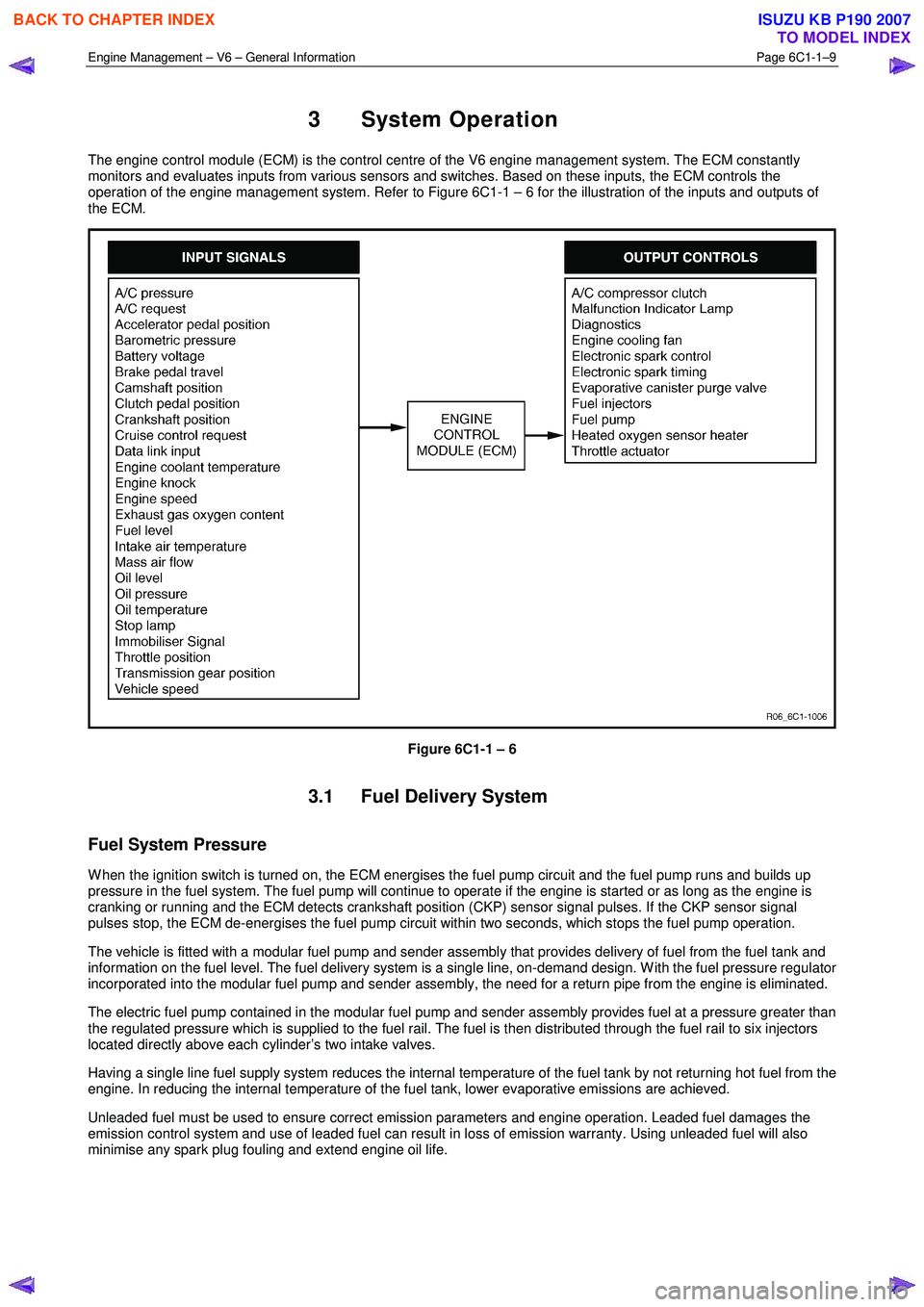
The engine control module (ECM) is the control centre of the V6 engine management system. The ECM constantly
monitors and evaluates inputs from various sensors and switches. Based on these inputs, the ECM controls the
operation of the engine management system. Refer to Figure 6C1-1 – 6 for the illustration of the inputs and outputs of
the ECM.
Figure 6C1-1 – 6
3.1 Fuel Delivery System
Fuel System Pressure
W hen the ignition switch is turned on, the ECM energises the fuel pump circuit and the fuel pump runs and builds up
pressure in the fuel system. The fuel pump will continue to operate if the engine is started or as long as the engine is
cranking or running and the ECM detects crankshaft position (CKP) sensor signal pulses. If the CKP sensor signal
pulses stop, the ECM de-energises the fuel pump circuit within two seconds, which stops the fuel pump operation.
The vehicle is fitted with a modular fuel pump and sender assembly that provides delivery of fuel from the fuel tank and
information on the fuel level. The fuel delivery system is a single line, on-demand design. W ith the fuel pressure regulator
incorporated into the modular fuel pump and sender assembly, the need for a return pipe from the engine is eliminated.
The electric fuel pump contained in the modular fuel pump and sender assembly provides fuel at a pressure greater than
the regulated pressure which is supplied to the fuel rail. The fuel is then distributed through the fuel rail to six injectors
located directly above each cylinder’s two intake valves.
Having a single line fuel supply system reduces the internal temperature of the fuel tank by not returning hot fuel from the
engine. In reducing the internal temperature of the fuel tank, lower evaporative emissions are achieved.
Unleaded fuel must be used to ensure correct emission parameters and engine operation. Leaded fuel damages the
emission control system and use of leaded fuel can result in loss of emission warranty. Using unleaded fuel will also
minimise any spark plug fouling and extend engine oil life.
BACK TO CHAPTER INDEX
TO MODEL INDEX
ISUZU KB P190 2007
Page 3321 of 6020
Engine Management – V6 – Diagnostics Page 6C1-2–43
6 Remove the upper intake manifold assembly, refer to 6A1 Engine Mechanical – V6.
NOTE
After removing the upper intake manifold, plug
the lower manifold opening to prevent dirt and
other contaminants from entering.
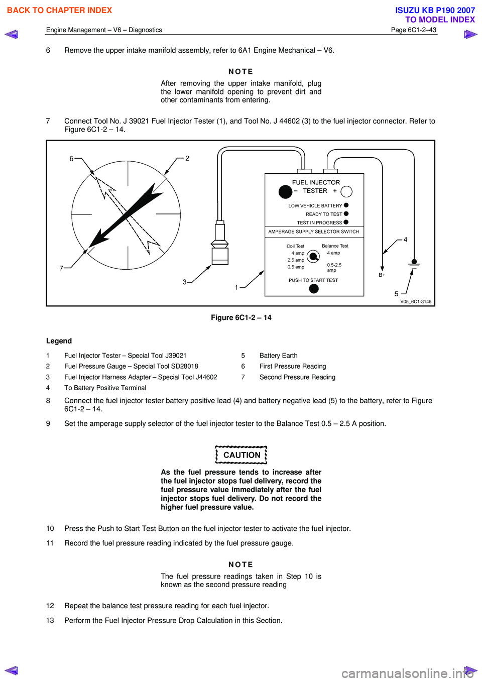
7 Connect Tool No. J 39021 Fuel Injector Tester (1), and Tool No. J 44602 (3) to the fuel injector connector. Refer to Figure 6C1-2 – 14.
Figure 6C1-2 – 14
Legend
1 Fuel Injector Tester – Special Tool J39021
2 Fuel Pressure Gauge – Special Tool SD28018
3 Fuel Injector Harness Adapter – Special Tool J44602
4 To Battery Positive Terminal 5 Battery Earth
6 First Pressure Reading
7 Second Pressure Reading
8 Connect the fuel injector tester battery positive lead (4) and battery negative lead (5) to the battery, refer to Figure 6C1-2 – 14.
9 Set the amperage supply selector of the fuel injector tester to the Balance Test 0.5 – 2.5 A position.
As the fuel pressure tends to increase after
the fuel injector stops fuel delivery, record the
fuel pressure value immediately after the fuel
injector stops fuel delivery. Do not record the
higher fuel pressure value.
10 Press the Push to Start Test Button on the fuel injector tester to activate the fuel injector.
11 Record the fuel pressure reading indicated by the fuel pressure gauge.
NOTE
The fuel pressure readings taken in Step 10 is
known as the second pressure reading
12 Repeat the balance test pressure reading for each fuel injector.
13 Perform the Fuel Injector Pressure Drop Calculation in this Section.
BACK TO CHAPTER INDEX
TO MODEL INDEX
ISUZU KB P190 2007
Page 3324 of 6020
Engine Management – V6 – Diagnostics Page 6C1-2–46
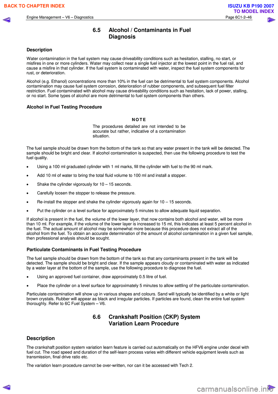
6.5 Alcohol / Contaminants in Fuel
Diagnosis
Description
W ater contamination in the fuel system may cause driveability conditions such as hesitation, stalling, no start, or
misfires in one or more cylinders. W ater may collect near a single fuel injector at the lowest point in the fuel rail, and
cause a misfire in that cylinder. If the fuel system is contaminated with water, inspect the fuel system components for
rust, or deterioration.
Alcohol (e.g. Ethanol) concentrations more than 10% in the fuel can be detrimental to fuel system components. Alcohol
contamination may cause fuel system corrosion, deterioration of rubber components, and subsequent fuel filter
restriction. Fuel contaminated with alcohol may cause driveability conditions such as hesitation, lack of power, stalling,
or no start. Some types of alcohol are more detrimental to fuel system components than others.
Alcohol in Fuel Testing Procedure
NOTE
The procedures detailed are not intended to be
accurate but rather, indicative of a contamination
situation.
The fuel sample should be drawn from the bottom of the tank so that any water present in the tank will be detected. The
sample should be bright and clear. If alcohol contamination is suspected, then use the following procedure to test the
fuel quality.
• Using a 100 ml graduated cylinder with 1 ml marks, fill the cylinder with fuel to the 90 ml mark.
• Add 10 ml of water to bring the total fluid volume to 100 ml and install a stopper.
• Shake the cylinder vigorously for 10 – 15 seconds.
• Carefully loosen the stopper to release the pressure.
• Re-install the stopper and shake the cylinder vigorously again for 10 – 15 seconds.
• Put the cylinder on a level surface for approximately 5 minutes to allow adequate liquid separation.
If alcohol is present in the fuel, the volume of the lower layer, that now contains both alcohol and water, will be more
than 10 ml. For example, if the volume of the lower layer is increased to 15 ml, this indicates at least 5 percent alcohol in
the fuel. The actual amount of alcohol may be somewhat more because this procedure does not extract all of the
alcohol from the fuel. To obtain an accurate determination of the amount of alcohol contamination in a given fuel sample,
then professional analysis should be sought.
Particulate Contaminants in Fuel Testing Procedure
The fuel sample should be drawn from the bottom of the tank so that any contaminants present in the tank will be
detected. The sample should be bright and clear. If the sample appears cloudy or contaminated with water as indicated
by a water layer at the bottom of the sample, use the following procedure to diagnose the fuel.
• Using an approved fuel container, draw approximately 0.5 litre of fuel.
• Place the cylinder on a level surface for approximately 5 minutes to allow settling of the particulate contamination.
Particulate contamination will show up in various shapes and colours. Sand will typically be identified by a white or light
brown crystals. Rubber will appear as black and irregular particles. If particles are found, clean the entire fuel system
thoroughly. Refer to 6C Fuel System – V6.
6.6 Crankshaft Position (CKP) System
Variation Learn Procedure
Description
The crankshaft position system variation learn feature is carried out automatically on the HFV6 engine under decel with
fuel cut. The road speed and duration of the self-learn process varies with different vehicle equipment levels such as
transmission, final drive ratio etc.
The variation learn procedure cannot be over-written, nor can it be accessed with Tech 2.
BACK TO CHAPTER INDEX
TO MODEL INDEX
ISUZU KB P190 2007
Page 3385 of 6020
Engine Management – V6 – Diagnostics Page 6C1-2–107
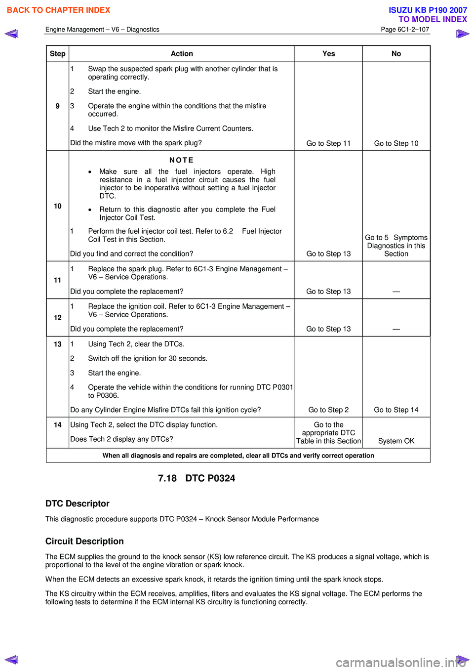
Step Action Yes No
9 1 Swap the suspected spark plug with another cylinder that is
operating correctly.
2 Start the engine.
3 Operate the engine within the conditions that the misfire occurred.
4 Use Tech 2 to monitor the Misfire Current Counters.
Did the misfire move with the spark plug? Go to Step 11 Go to Step 10
10 NOTE
• Make sure all the fuel injectors operate. High
resistance in a fuel injector circuit causes the fuel
injector to be inoperative without setting a fuel injector
DTC.
• Return to this diagnostic after you complete the Fuel
Injector Coil Test.
1 Perform the fuel injector coil test. Refer to 6.2 Fuel Injector Coil Test in this Section.
Did you find and correct the condition? Go to Step 13 Go to 5 Symptoms
Diagnostics in this Section
11 1 Replace the spark plug. Refer to 6C1-3 Engine Management –
V6 – Service Operations.
Did you complete the replacement? Go to Step 13 —
12 1 Replace the ignition coil. Refer to 6C1-3 Engine Management –
V6 – Service Operations.
Did you complete the replacement? Go to Step 13 —
13 1 Using Tech 2, clear the DTCs.
2 Switch off the ignition for 30 seconds.
3 Start the engine.
4 Operate the vehicle within the conditions for running DTC P0301 to P0306.
Do any Cylinder Engine Misfire DTCs fail this ignition cycle? Go to Step 2 Go to Step 14
14 Using Tech 2, select the DTC display function.
Does Tech 2 display any DTCs? Go to the
appropriate DTC
Table in this Section System OK
When all diagnosis and repairs are completed, clear all DTCs and verify correct operation
7.18 DTC P0324
DTC Descriptor
This diagnostic procedure supports DTC P0324 – Knock Sensor Module Performance
Circuit Description
The ECM supplies the ground to the knock sensor (KS) low reference circuit. The KS produces a signal voltage, which is
proportional to the level of the engine vibration or spark knock.
W hen the ECM detects an excessive spark knock, it retards the ignition timing until the spark knock stops.
The KS circuitry within the ECM receives, amplifies, filters and evaluates the KS signal voltage. The ECM performs the
following tests to determine if the ECM internal KS circuitry is functioning correctly.
BACK TO CHAPTER INDEX
TO MODEL INDEX
ISUZU KB P190 2007
Page 3513 of 6020
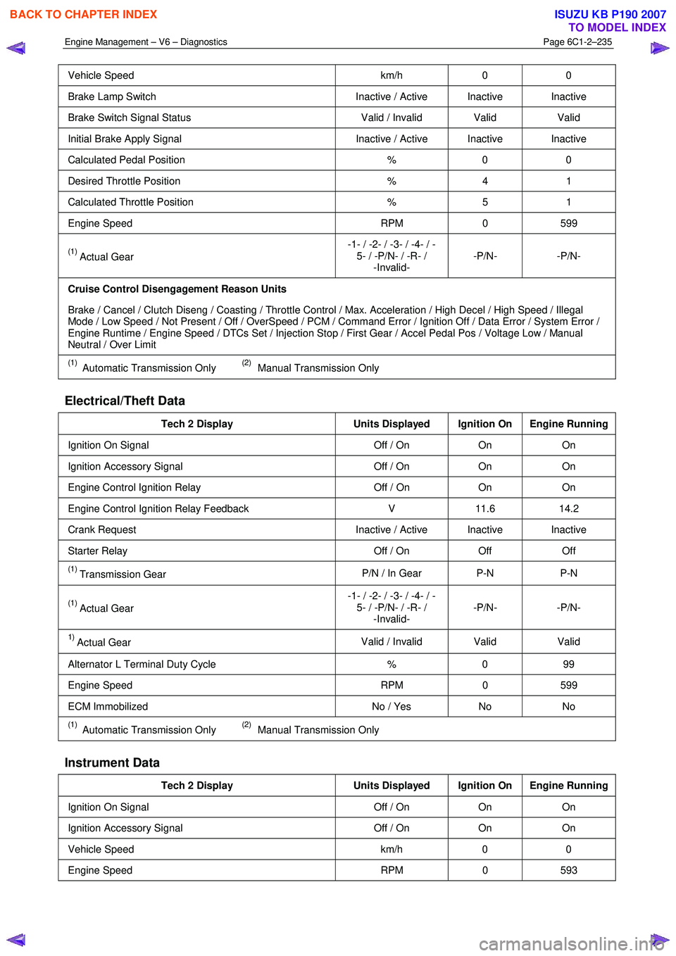
Engine Management – V6 – Diagnostics Page 6C1-2–235
Vehicle Speed km/h 0 0
Brake Lamp Switch Inactive / Active Inactive Inactive
Brake Switch Signal Status Valid / Invalid Valid Valid
Initial Brake Apply Signal Inactive / Active Inactive Inactive
Calculated Pedal Position % 0 0
Desired Throttle Position % 4 1
Calculated Throttle Position % 5 1
Engine Speed RPM 0 599
(1) Actual Gear -1- / -2- / -3- / -4- / -
5- / -P/N- / -R- / -Invalid- -P/N- -P/N-
Cruise Control Disengagement Reason Units
Brake / Cancel / Clutch Diseng / Coasting / Throttle Control / Max. Acceleration / High Decel / High Speed / Illegal
Mode / Low Speed / Not Present / Off / OverSpeed / PCM / Command Error / Ignition Off / Data Error / System Error /
Engine Runtime / Engine Speed / DTCs Set / Injection Stop / First Gear / Accel Pedal Pos / Voltage Low / Manual
Neutral / Over Limit
(1) Automatic Transmission Only (2) Manual Transmission Only
Electrical/Theft Data
Tech 2 Display Units Displayed Ignition On Engine Running
Ignition On Signal Off / On On On
Ignition Accessory Signal Off / On On On
Engine Control Ignition Relay Off / On On On
Engine Control Ignition Relay Feedback V 11.6 14.2
Crank Request Inactive / Active Inactive Inactive
Starter Relay Off / On Off Off
(1) Transmission Gear P/N / In Gear P-N P-N
(1) Actual Gear -1- / -2- / -3- / -4- / -
5- / -P/N- / -R- / -Invalid- -P/N- -P/N-
1) Actual Gear
Valid / Invalid Valid
Valid
Alternator L Terminal Duty Cycle % 0 99
Engine Speed RPM 0 599
ECM Immobilized No / Yes No No
(1) Automatic Transmission Only (2) Manual Transmission Only
Instrument Data
Tech 2 Display Units Displayed Ignition On Engine Running
Ignition On Signal Off / On On On
Ignition Accessory Signal Off / On On On
Vehicle Speed km/h 0 0
Engine Speed RPM 0 593
BACK TO CHAPTER INDEX
TO MODEL INDEX
ISUZU KB P190 2007
Page 3530 of 6020
Engine Management – V6 – Service Operations Page 6C1-3–6
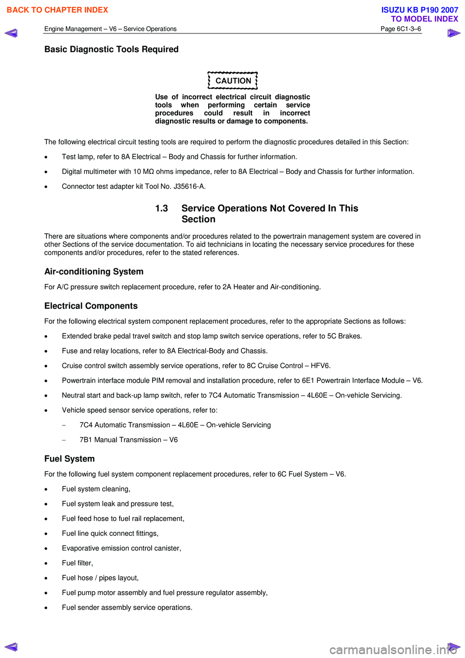
Basic Diagnostic Tools Required
Use of incorrect electrical circuit diagnostic
tools when performing certain service
procedures could result in incorrect
diagnostic results or damage to components.
The following electrical circuit testing tools are required to perform the diagnostic procedures detailed in this Section:
• Test lamp, refer to 8A Electrical – Body and Chassis for further information.
• Digital multimeter with 10 M Ω ohms impedance, refer to 8A Electrical – Body and Chassis for further information.
• Connector test adapter kit Tool No. J35616-A.
1.3 Service Operations Not Covered In This
Section
There are situations where components and/or procedures related to the powertrain management system are covered in
other Sections of the service documentation. To aid technicians in locating the necessary service procedures for these
components and/or procedures, refer to the stated references.
Air-conditioning System
For A/C pressure switch replacement procedure, refer to 2A Heater and Air-conditioning.
Electrical Components
For the following electrical system component replacement procedures, refer to the appropriate Sections as follows:
• Extended brake pedal travel switch and stop lamp switch service operations, refer to 5C Brakes.
• Fuse and relay locations, refer to 8A Electrical-Body and Chassis.
• Cruise control switch assembly service operations, refer to 8C Cruise Control – HFV6.
• Powertrain interface module PIM removal and installation procedure, refer to 6E1 Powertrain Interface Module – V6.
• Neutral start and back-up lamp switch, refer to 7C4 Automatic Transmission – 4L60E – On-vehicle Servicing.
• Vehicle speed sensor service operations, refer to:
− 7C4 Automatic Transmission – 4L60E – On-vehicle Servicing
− 7B1 Manual Transmission – V6
Fuel System
For the following fuel system component replacement procedures, refer to 6C Fuel System – V6.
• Fuel system cleaning,
• Fuel system leak and pressure test,
• Fuel feed hose to fuel rail replacement,
• Fuel line quick connect fittings,
• Evaporative emission control canister,
• Fuel filter,
• Fuel hose / pipes layout,
• Fuel pump motor assembly and fuel pressure regulator assembly,
• Fuel sender assembly service operations.
BACK TO CHAPTER INDEX
TO MODEL INDEX
ISUZU KB P190 2007