2007 ISUZU KB P190 automatic transmission
[x] Cancel search: automatic transmissionPage 3185 of 6020
Engine Cooling – V6 Engine Page 6B1–50
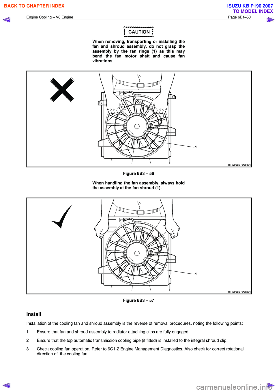
When removing, transporting or installing the
fan and shroud assembly, do not grasp the
assembly by the fan rings (1) as this may
bend the fan motor shaft and cause fan
vibrations
Figure 6B3 – 56
When handling the fan assembly, always hold
the assembly at the fan shroud (1).
Figure 6B3 – 57
Install
Installation of the cooling fan and shroud assembly is the reverse of removal procedures, noting the following points:
1 Ensure that fan and shroud assembly to radiator attaching clips are fully engaged.
2 Ensure that the top automatic transmission cooling pipe (if fitted) is installed to the integral shroud clip.
3 Check cooling fan operation. Refer to 6C1-2 Engine Management Diagnostics. Also check for correct rotational direction of the cooling fan.
BACK TO CHAPTER INDEX
TO MODEL INDEX
ISUZU KB P190 2007
Page 3188 of 6020
Engine Cooling – V6 Engine Page 6B1–53
NOTE
Should the spring clip or the O-ring seal in the
quick connect fitting be damaged during the line
removal process, then the complete fitting must
be replaced.
Reinstall
1 Remove the plugs installed in the transmission cooler line and hose openings and wipe all exposed parts
with a clean shop rag.
• Smear clean automatic transmission fluid on
each cooler line end, then push into the radiator
quick connect fittings. As a security check gently
pull on the connector to ensure correct
engagement.
• As a security check, push and clip each
verification disc into place over the quick-
connect fittings. If difficulty is experienced,
repeat the installation process until the
verification disc can be clipped into place over
the radiator quick-connect fitting.
If the verifier disc does not clip into place,
the quick-connect fitting is not engaged,
rectify this before proceeding.
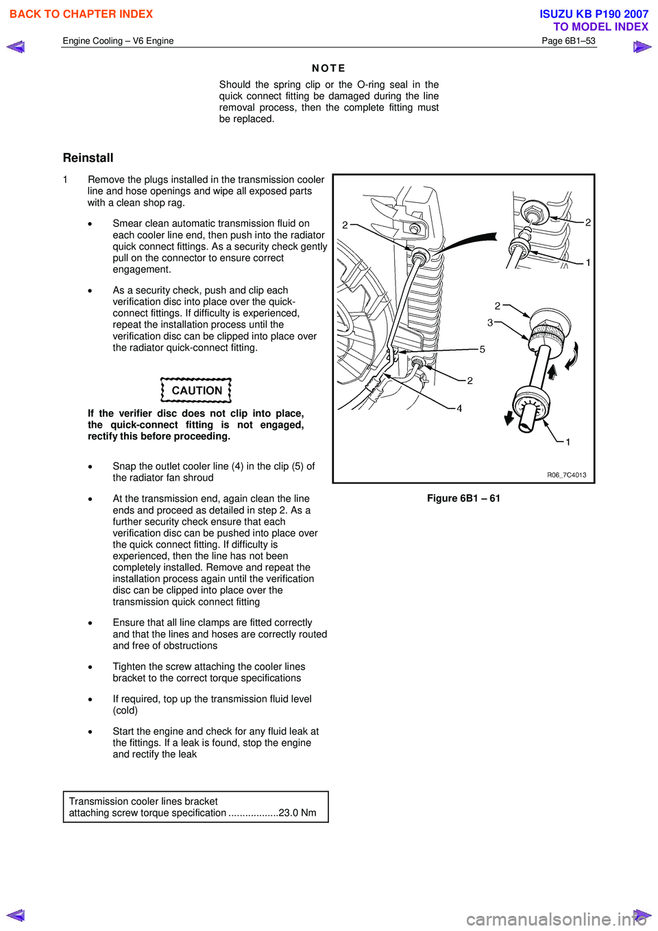
• Snap the outlet cooler line (4) in the clip (5) of
the radiator fan shroud
• At the transmission end, again clean the line
ends and proceed as detailed in step 2. As a
further security check ensure that each
verification disc can be pushed into place over
the quick connect fitting. If difficulty is
experienced, then the line has not been
completely installed. Remove and repeat the
installation process again until the verification
disc can be clipped into place over the
transmission quick connect fitting
• Ensure that all line clamps are fitted correctly
and that the lines and hoses are correctly routed
and free of obstructions
• Tighten the screw attaching the cooler lines
bracket to the correct torque specifications
• If required, top up the transmission fluid level
(cold)
• Start the engine and check for any fluid leak at
the fittings. If a leak is found, stop the engine
and rectify the leak
Figure 6B1 – 61
Transmission cooler lines bracket
attaching screw torque specification ..................23.0 Nm
BACK TO CHAPTER INDEX
TO MODEL INDEX
ISUZU KB P190 2007
Page 3191 of 6020
Engine Cooling – V6 Engine Page 6B1–56
Reinstall
Installation of the radiator is the reverse of removal procedures, noting the following points:
1 Before installing radiator, inspect core to ensure that there is no foreign matter in core fins. Clean out between core fins with compressed air, blowing from rear to front.
2 If the vehicle is fitted with an automatic transmission, remove plugs from the removed cooling pipe ends and the two quick connect fittings.
3 After wiping cooler line ends and smearing clean automatic transmission fluid over each flared line end, push into the quick connect fitting to engage. As a security check, tug on each line to ensure correct engagement.
4 Check the transmission fluid level. Refer to the following references as required:
• 7C4 Automatic Transmission
• 4L60E On-vehicle Servicing
5 Install the following hoses:
a. Lower radiator hose, securing with the hose clamp.
b. Upper radiator hose, securing with the hose clamp.
6 Install the radiator cooling fan and shroud assembly. Refer to 3.13Cooling Fan and Shroud Assembly in this Section. Ensure that electrical connectors and the transmission cooler lines are seated correctly in the integral
retainer clips before install upper radiator shroud.
7 Refill cooling system. Refer to 3.3 Draining and Filling Cooling System in this Section.
8 Check for coolant leaks. Refer to 3.7 Pressure Testing in this Section.
9 Reconnect battery ground lead. Refer to 8A Electrical Body & Chassis.
10 Check cooling fan operation. Refer to 6C1-2 Engine Management Diagnostics. Also check for correct rotational direction of cooling fan.
BACK TO CHAPTER INDEX
TO MODEL INDEX
ISUZU KB P190 2007
Page 3192 of 6020
Engine Cooling – V6 Engine Page 6B1–57
Radiator Repair Procedure
Repairable Leaks
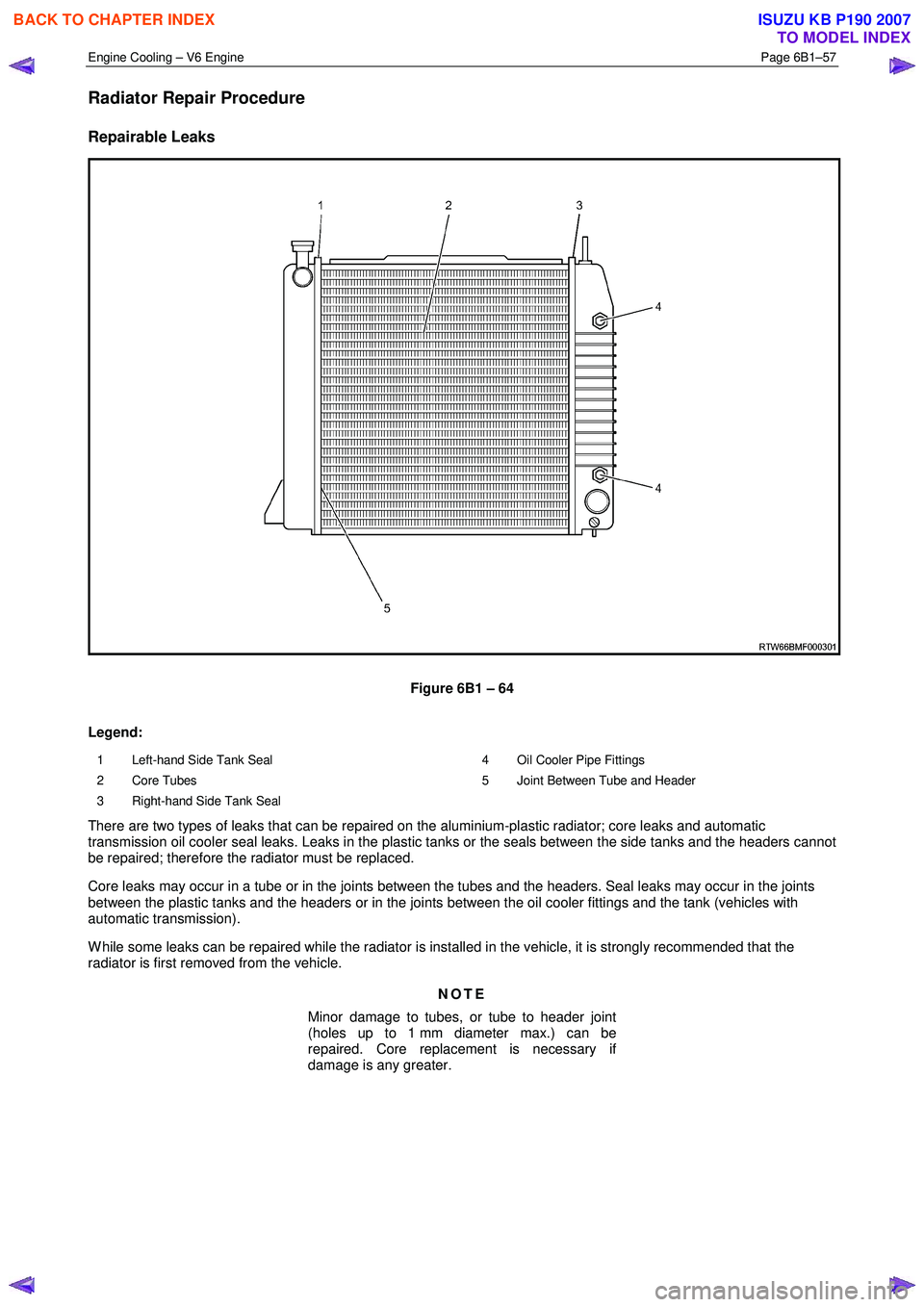
Figure 6B1 – 64
Legend:
1 Left-hand Side Tank Seal
2 Core Tubes
3 Right-hand Side Tank Seal 4 Oil Cooler Pipe Fittings
5 Joint Between Tube and Header
There are two types of leaks that can be repaired on the aluminium-plastic radiator; core leaks and automatic
transmission oil cooler seal leaks. Leaks in the plastic tanks or the seals between the side tanks and the headers cannot
be repaired; therefore the radiator must be replaced.
Core leaks may occur in a tube or in the joints between the tubes and the headers. Seal leaks may occur in the joints
between the plastic tanks and the headers or in the joints between the oil cooler fittings and the tank (vehicles with
automatic transmission).
W hile some leaks can be repaired while the radiator is installed in the vehicle, it is strongly recommended that the
radiator is first removed from the vehicle.
NOTE
Minor damage to tubes, or tube to header joint
(holes up to 1 mm diameter max.) can be
repaired. Core replacement is necessary if
damage is any greater.
BACK TO CHAPTER INDEX
TO MODEL INDEX
ISUZU KB P190 2007
Page 3198 of 6020
Engine Cooling – V6 Engine Page 6B1–63
4.5 Problems Not Requiring Disassembly of
Cooling System
1 Large obstructions blocking radiator or condenser airflow.
• Auxiliary oil coolers
• License plate
• Obstruction of radiator grille, for example, driving lights or mud
2 Loose, damaged or missing air chute side panels.
3 Missing or damaged air baffle.
4 Cracked or loose coolant recovery system hose.
5 Leaking heater component such as the heater core or water valve.
4.6 Problems Requiring Disassembly of Cooling System
1 Damaged cooling fan or faulty motor operation.
2 Pressure test cooling system.
3 Defective coolant pump.
• Eroded or broken impeller vanes
• Failed bearing or seal – check for shaft or bearing end play
4 Internally blocked radiator core.
5 Obstruction of coolant recovery system.
6 Internal system leaks.
• Head gaskets
• Cracked cylinder block
• Engine front cover
• Intake manifold gaskets
7 Blocked coolant passages in cylinder heads or block – remove cylinder heads and check.
4.7 Black Light and Dye Leak Diagnosis Method
It is strongly recommended that this diagnostic method be used to diagnose fluid leaks. This method is a proven and
reliable method that identifies the specific leak source.
The black light kit can be used for the leak detection of a number of fluids, when used with the appropriate tracer dye.
Examples are: Coolant, Engine Oil, Automatic Transmission Fluid and Air Conditioning Refrigerant (R134A).
The following is a summary of the steps involved in detecting a cooling system fluid leak using black light and dye:
1 Pour specified amount of dye into the cooling system via the coolant filler cap on the outlet housing. Refer 3.1 Service Notes in this Section.
2 Road test the vehicle under normal operating conditions.
3 Direct the light towards the suspect area. The fluid leak will appear as a brightly coloured path leading from the source.
4 Repair fluid leak and recheck to ensure that leak has been rectified.
5 Refer to the manufacturer’s directions when using this method.
BACK TO CHAPTER INDEX
TO MODEL INDEX
ISUZU KB P190 2007
Page 3199 of 6020
Engine Cooling – V6 Engine Page 6B1–64
5 Specifications
General
Coolant Filler Cap Pressure Rating .............................................................................120 kPa
Cooling System Capacity
Automatic Transmission ........................................................................................ 9.9 litres
Manual Transmission .......................................................................................... 10.3 litres
Coolant Corrosion Inhibitor Quantity W hen Refilling System Automatic Transmission Models......................................................................... 5 litres
Manual Transmission Models .......................................................................... 5.2 litres
NOTE
DEX-COOL® long life coolant or equivalent such
as Extended Life Anti-freeze Coolant, conforming
to GM Specification 6277M, must be used when
changing coolant.
Thermostat Type...............................................................................................Power element (wax pellet)
Start to Open at ......................................................................................................... 82 ± 2 ° C
Fully Open at .......................................................................................................... 95° C ma x.
Coolant Pump
Type........................................................................................................................ Cen trifugal
Drive ................................................................................................ Multi-Vee Serpentine Belt
Bearing Type .................................................................................... Double Row Ball Bearing
Radiator
Core type ......................................................................................... Aluminium crossflow core
Overall width ................................................................................................................ 66 4 mm
Core width.................................................................................................................... 5 10 mm
Overall height............................................................................................................... 60 2 mm
Core height .................................................................................................................. 51 2 mm
Core thickness ............................................................................................................... 27 mm
Plastic Tanks .............................................................................. Nylon 6.6 (30% Glass Filled)
Radiator Hoses Lower Upper
Number ............................................................................... One............................. One
Type................................................................................ Moulded ...................... Moulded
Inside diameter ................................................................. 34 mm ........................ 34 mm
BACK TO CHAPTER INDEX
TO MODEL INDEX
ISUZU KB P190 2007
Page 3202 of 6020
Engine Cooling – V6 Engine Page 6B1–67
7 Special Tools
Tool number Illustration Description Classification
AU505
Coolant Tester
Used for testing the coolant
concentration level.
Previously released. Mandatory
AU525
Quick Connect Release Tool
Used to release the quick connect
fittings on automatic transmission fluid
cooler lines at the radiator end, when
fitted.
Previously released. Mandatory
BT3373–F
Belt Tension Gauge
Used when checking drive and
accessory belt tension and
adjustments.
Previously released. Desirable
J 26568 Refractometer
Used for testing coolant concentration
level.
Previously released, as AU 435. Mandatory
J28431–B Fluid Dye
Available in 24 x 1-ounce bottles.
Used in conjunction with a black light
such as J42220 to locate the source
of various fluid leaks.
Previously released. Desirable
J42220 Black Light, Leak Detection Lamp
Used with dye, J28431–B to locate the
source of various vehicle fluid leaks.
Previously released. Desirable
N/A Cooling System Pressure Tester
Previously released. Commercially available. Mandatory
BACK TO CHAPTER INDEX
TO MODEL INDEX
ISUZU KB P190 2007
Page 3254 of 6020
Engine Management – V6 – General Information Page 6C1-1–12
Battery Voltage Correction Mode
The ECM monitors the battery voltage circuit to ensure the voltage available to the engine management system stays
within the specified range. A low system voltage changes the voltage across the fuel injectors, which affects the fuel
injector flow rate. In addition, a low system voltage fault condition may cause other engine management system
components to malfunction.
The ECM switches to battery voltage correction mode when the ECM detects a low battery voltage fault condition. W hile
in battery voltage correction mode, the ECM performs the following functions to compensate for the low system voltage:
• Increases the injector on-time to maintain the correct amount of fuel being delivered, and
• Increases the idle speed to increase the generator output.
Limp Mode
The programming in the ECM software allows the engine to run in a back-up fuel strategy or limp mode when the ECM
fails to receive signal inputs from critical sensors or when a critical engine management fault condition exists.
The ECM switches to limp mode to enable the vehicle to be driven until service operations can be performed.
Engine Protection Mode
Engine protection mode is engaged to protect engine components from friction damage in the event of an engine over-
temperature condition being detected by the ECM.
W hen the ECM is in engine protection mode, fuel injectors are systematically disabled and re-activated. The injectors
that have been shut down allow the air being drawn into the engine to assist with engine cooling.
Clear Flood Mode
If the engine is flooded with fuel during starting and will not start, the clear flood mode can be manually selected by
depressing the accelerator pedal to wide open throttle (W OT). In this mode, the ECM will completely disable the fuel
injectors, and will maintain this state during engine cranking as long as the ECM detects a W OT condition with engine
speed less than 1,000 rpm.
3.3 Ignition Control System
The electronic ignition system provides a spark to ignite the compressed air / fuel mixture at the correct time. The ECM
maintains correct spark timing and dwell for all engine operating conditions. The ECM calculates the optimum spark
parameters from information received from the various sensors and triggers the appropriate ignition module / coil to fire
the spark plug.
3.4 Starter Motor Operation
The engine control module controls the activation of the start relay in response to inputs from:
• Ignition switch,
• Battery,
• Immobiliser system, and
• Automatic transmission gear selector position / clutch pedal position switch for vehicles with manual transmissions.
3.5 Throttle Actuator Control System
Description
The throttle actuator control (TAC) system is used to improve emissions, fuel economy and driveability. The TAC system
eliminates the mechanical link between the accelerator pedal and the throttle plate and eliminates the need for a cruise
control module and idle air control motor. The TAC system comprises of:
BACK TO CHAPTER INDEX
TO MODEL INDEX
ISUZU KB P190 2007