2007 ISUZU KB P190 automatic transmission
[x] Cancel search: automatic transmissionPage 1246 of 6020
6E-212 Engine Control System (4JH1)
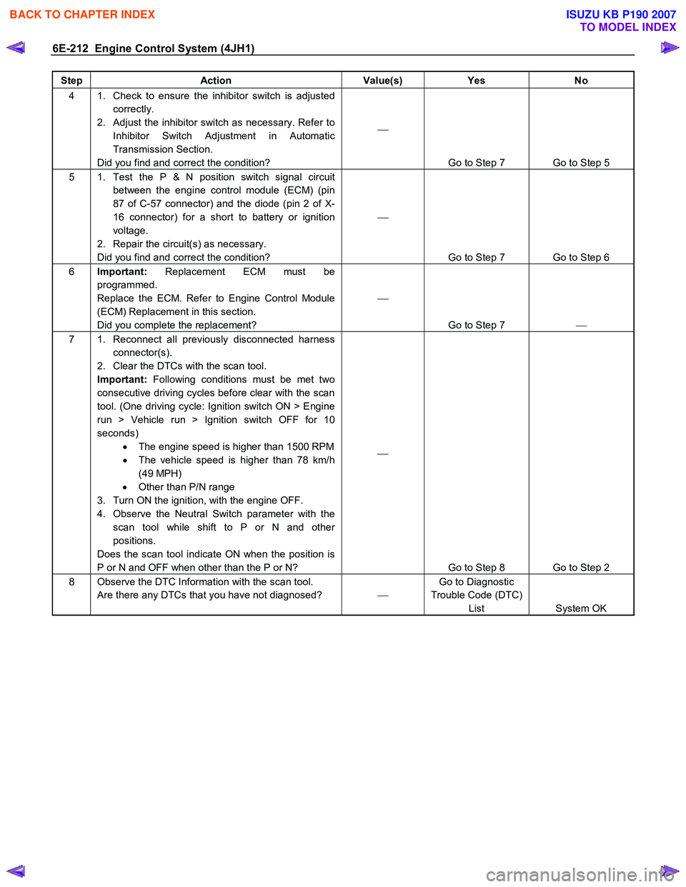
Step Action Value(s) Yes No
4 1. Check to ensure the inhibitor switch is adjusted
correctly.
2. Adjust the inhibitor switch as necessary. Refer to Inhibitor Switch Adjustment in Automatic
Transmission Section.
Did you find and correct the condition?
Go to Step 7 Go to Step 5
5 1. Test the P & N position switch signal circuit between the engine control module (ECM) (pin
87 of C-57 connector) and the diode (pin 2 of X-
16 connector) for a short to battery or ignition
voltage.
2. Repair the circuit(s) as necessary.
Did you find and correct the condition?
Go to Step 7 Go to Step 6
6 Important: Replacement ECM must be
programmed.
Replace the ECM. Refer to Engine Control Module
(ECM) Replacement in this section.
Did you complete the replacement?
Go to Step 7
7 1. Reconnect all previously disconnected harness
connector(s).
2. Clear the DTCs with the scan tool.
Important: Following conditions must be met two
consecutive driving cycles before clear with the scan
tool. (One driving cycle: Ignition switch ON > Engine
run > Vehicle run > Ignition switch OFF for 10
seconds) • The engine speed is higher than 1500 RPM
• The vehicle speed is higher than 78 km/h
(49 MPH)
• Other than P/N range
3. Turn ON the ignition, with the engine OFF.
4. Observe the Neutral Switch parameter with the scan tool while shift to P or N and other
positions.
Does the scan tool indicate ON when the position is
P or N and OFF when other than the P or N?
Go to Step 8 Go to Step 2
8 Observe the DTC Information with the scan tool. Are there any DTCs that you have not diagnosed? Go to Diagnostic
Trouble Code (DTC) List System OK
BACK TO CHAPTER INDEX
TO MODEL INDEX
ISUZU KB P190 2007
Page 1312 of 6020
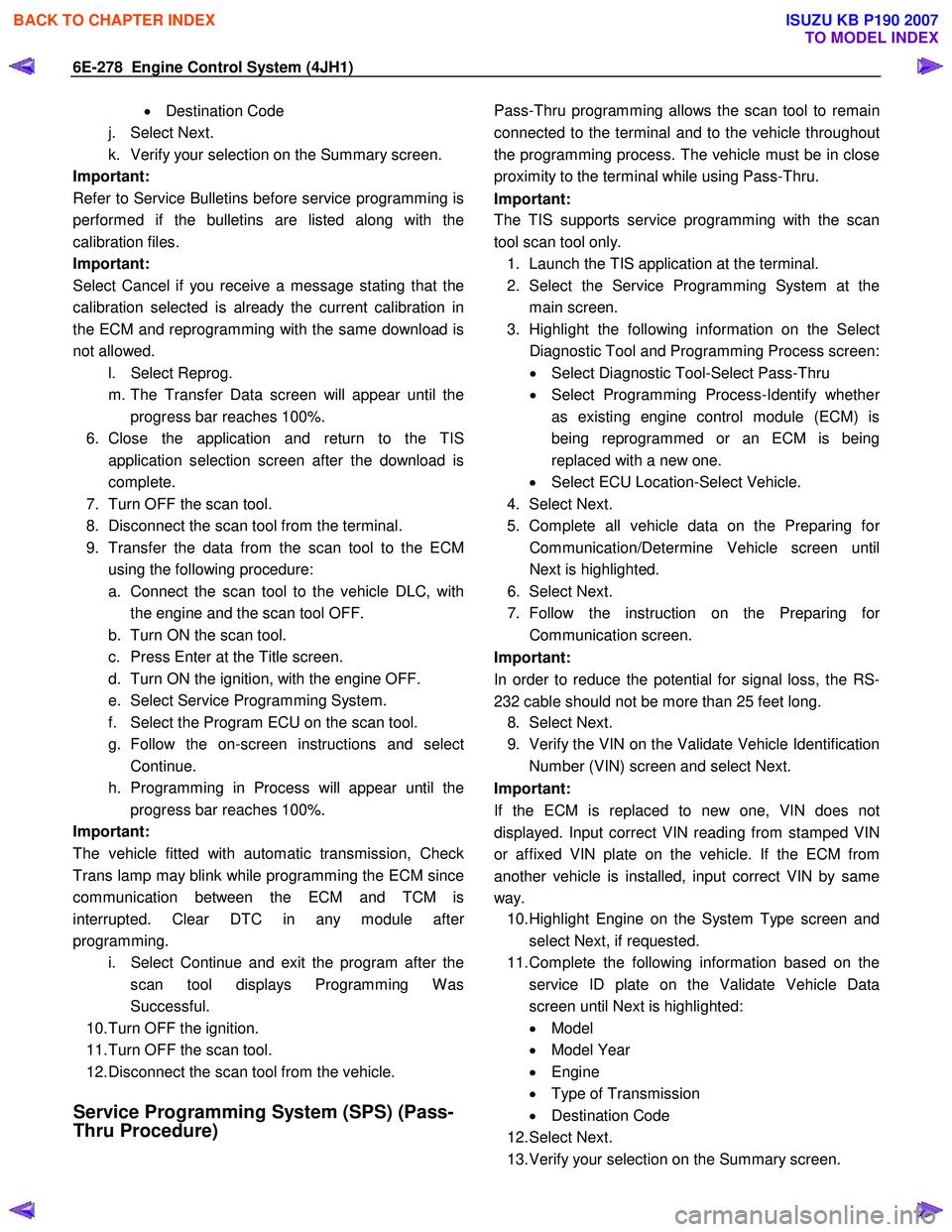
6E-278 Engine Control System (4JH1)
• Destination Code
j. Select Next.
k. Verify your selection on the Summary screen.
Important:
Refer to Service Bulletins before service programming is
performed if the bulletins are listed along with the
calibration files.
Important:
Select Cancel if you receive a message stating that the
calibration selected is already the current calibration in
the ECM and reprogramming with the same download is
not allowed.
l. Select Reprog.
m. The Transfer Data screen will appear until the progress bar reaches 100%.
6. Close the application and return to the TIS application selection screen after the download is
complete.
7. Turn OFF the scan tool.
8. Disconnect the scan tool from the terminal.
9. Transfer the data from the scan tool to the ECM using the following procedure:
a. Connect the scan tool to the vehicle DLC, with the engine and the scan tool OFF.
b. Turn ON the scan tool.
c. Press Enter at the Title screen.
d. Turn ON the ignition, with the engine OFF.
e. Select Service Programming System.
f. Select the Program ECU on the scan tool.
g. Follow the on-screen instructions and select Continue.
h. Programming in Process will appear until the progress bar reaches 100%.
Important:
The vehicle fitted with automatic transmission, Check
Trans lamp may blink while programming the ECM since
communication between the ECM and TCM is
interrupted. Clear DTC in any module afte
r
programming.
i. Select Continue and exit the program after the scan tool displays Programming W as
Successful.
10. Turn OFF the ignition.
11. Turn OFF the scan tool.
12. Disconnect the scan tool from the vehicle.
Service Programming System (SPS) (Pass-
Thru Procedure)
Pass-Thru programming allows the scan tool to remain
connected to the terminal and to the vehicle throughou
t
the programming process. The vehicle must be in close
proximity to the terminal while using Pass-Thru.
Important:
The TIS supports service programming with the scan
tool scan tool only.
1. Launch the TIS application at the terminal.
2. Select the Service Programming System at the main screen.
3. Highlight the following information on the Selec
t
Diagnostic Tool and Programming Process screen:
• Select Diagnostic Tool-Select Pass-Thru
• Select Programming Process-Identify whethe
r
as existing engine control module (ECM) is
being reprogrammed or an ECM is being
replaced with a new one.
• Select ECU Location-Select Vehicle.
4. Select Next.
5. Complete all vehicle data on the Preparing fo
r
Communication/Determine Vehicle screen until
Next is highlighted.
6. Select Next.
7. Follow the instruction on the Preparing fo
r
Communication screen.
Important:
In order to reduce the potential for signal loss, the RS-
232 cable should not be more than 25 feet long.
8. Select Next.
9. Verify the VIN on the Validate Vehicle Identification Number (VIN) screen and select Next.
Important:
If the ECM is replaced to new one, VIN does no
t
displayed. Input correct VIN reading from stamped VIN
or affixed VIN plate on the vehicle. If the ECM from
another vehicle is installed, input correct VIN by same
way. 10. Highlight Engine on the System Type screen and
select Next, if requested.
11. Complete the following information based on the service ID plate on the Validate Vehicle Data
screen until Next is highlighted:
• Model
• Model Year
• Engine
• Type of Transmission
• Destination Code
12. Select Next.
13. Verify your selection on the Summary screen.
BACK TO CHAPTER INDEX
TO MODEL INDEX
ISUZU KB P190 2007
Page 1313 of 6020
Engine Control System (4JH1) 6E-279
Important:
Refer to Service Bulletins before service programming is
performed if the bulletins are listed along with the
calibration files.
Important:
Select Cancel if you receive a message stating that the
calibration selected is already the current calibration in
the scan tool and reprogramming with the same
download is not allowed.
14. Select Reprog.
15. The Transfer Data screen will appear until the progress bar reaches 100%.
Important:
The vehicle fitted with automatic transmission, Check
Trans lamp may blink while programming the ECM since
communication between the ECM and TCM is
interrupted. Clear DTC in any module afte
r
programming. 16. Select Close on the Programming Complete
screen.
17. Turn OFF the scan tool.
18. Disconnect the scan tool from the vehicle.
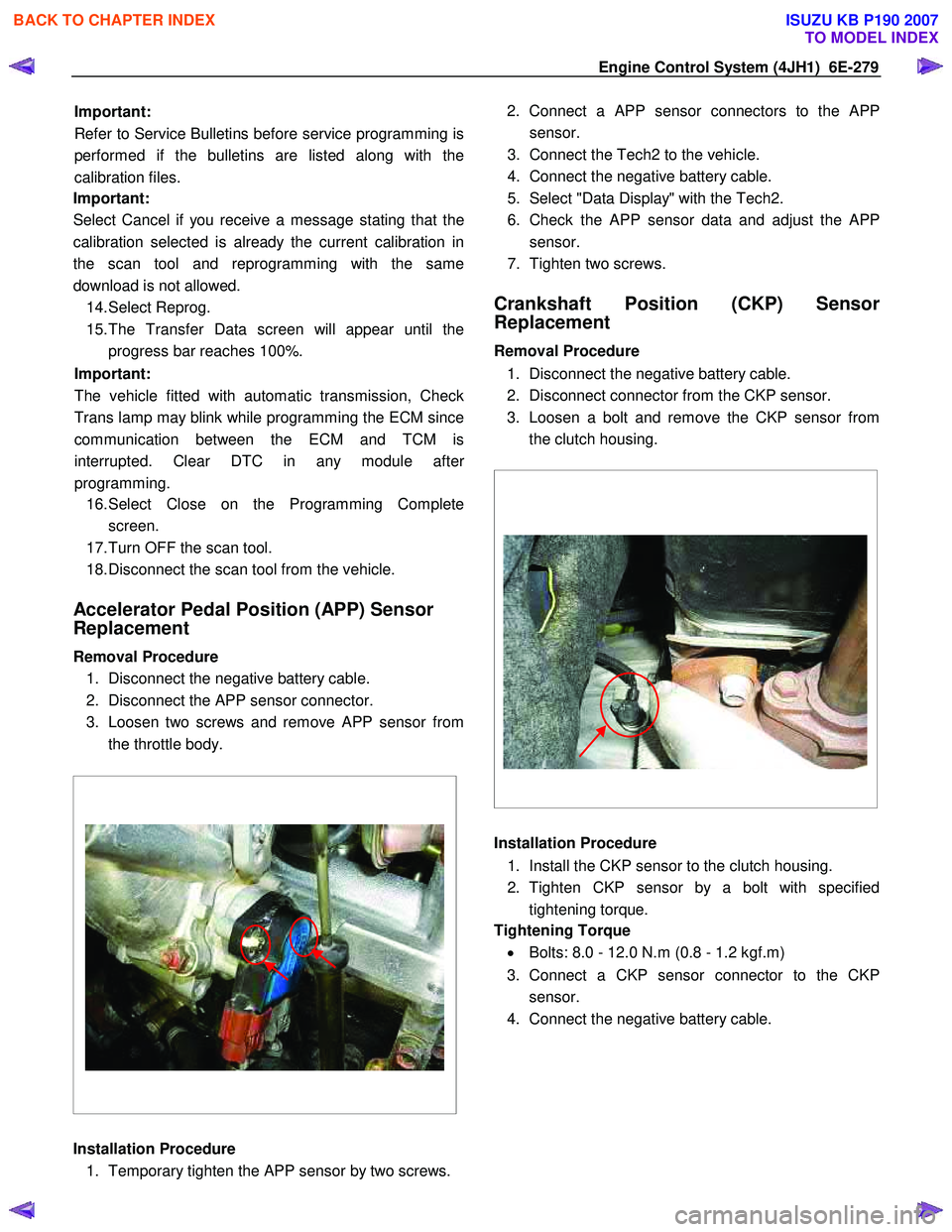
Accelerator Pedal Position (APP) Sensor
Replacement
Removal Procedure 1. Disconnect the negative battery cable.
2. Disconnect the APP sensor connector.
3. Loosen two screws and remove APP sensor from the throttle body.
Installation Procedure 1. Temporary tighten the APP sensor by two screws. 2. Connect a APP sensor connectors to the
APP
sensor.
3. Connect the Tech2 to the vehicle.
4. Connect the negative battery cable.
5. Select "Data Display" with the Tech2.
6. Check the APP sensor data and adjust the
APP
sensor.
7. Tighten two screws.
Crankshaft Position (CKP) Sensor
Replacement
Removal Procedure
1. Disconnect the negative battery cable.
2. Disconnect connector from the CKP sensor.
3. Loosen a bolt and remove the CKP sensor from the clutch housing.
Installation Procedure
1. Install the CKP sensor to the clutch housing.
2. Tighten CKP sensor by a bolt with specified tightening torque.
Tightening Torque
• Bolts: 8.0 - 12.0 N.m (0.8 - 1.2 kgf.m)
3. Connect a CKP sensor connector to the CKP sensor.
4. Connect the negative battery cable.
BACK TO CHAPTER INDEX
TO MODEL INDEX
ISUZU KB P190 2007
Page 1458 of 6020
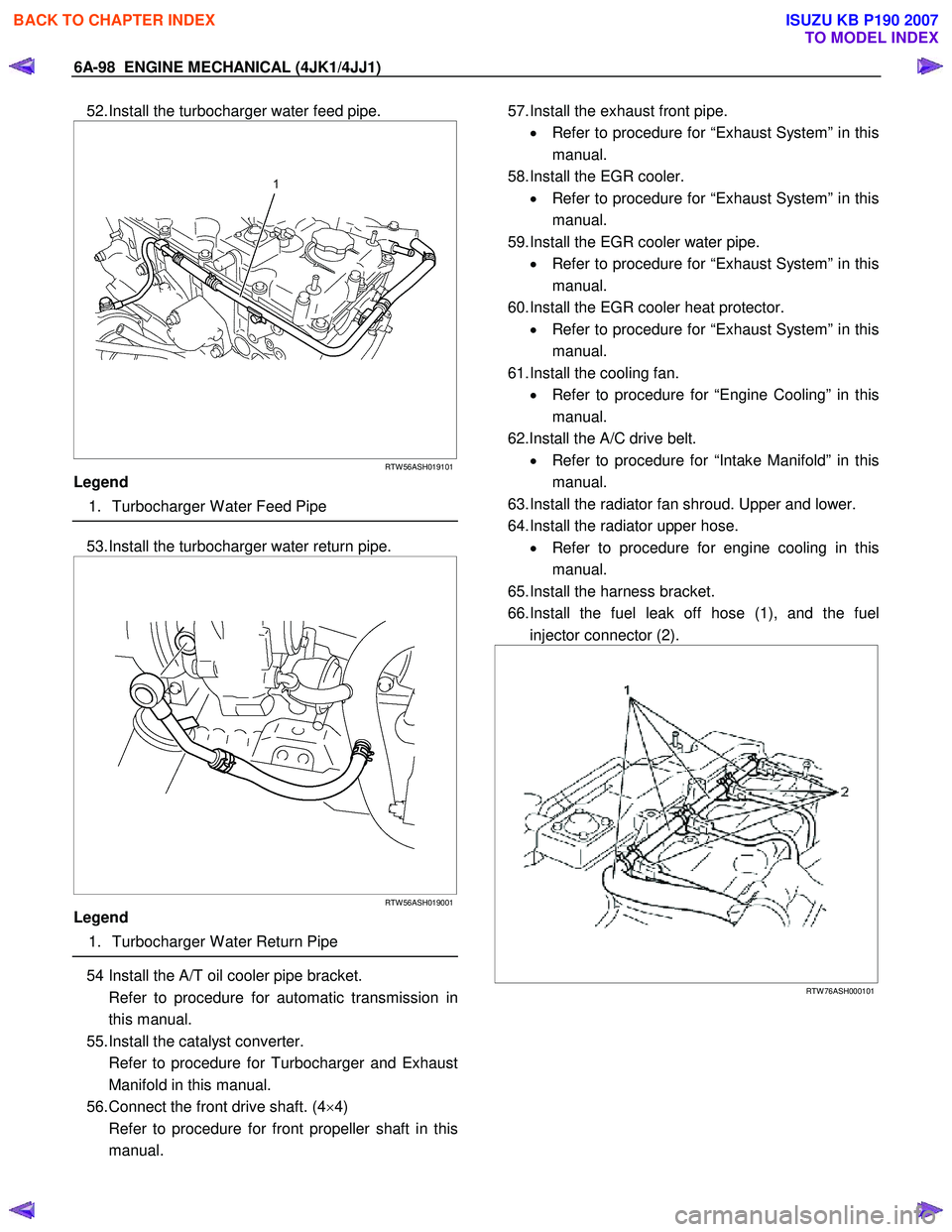
6A-98 ENGINE MECHANICAL (4JK1/4JJ1)
52. Install the turbocharger water feed pipe.
RTW 56ASH019101
Legend
1. Turbocharger W ater Feed Pipe
53. Install the turbocharger water return pipe.
RTW 56ASH019001
Legend
1. Turbocharger W ater Return Pipe
54 Install the A/T oil cooler pipe bracket.
Refer to procedure for automatic transmission in this manual.
55. Install the catalyst converter.
Refer to procedure for Turbocharger and Exhaust Manifold in this manual.
56. Connect the front drive shaft. (4 ×4)
Refer to procedure for front propeller shaft in this manual.
57. Install the exhaust front pipe.
• Refer to procedure for “Exhaust System” in this
manual.
58. Install the EGR cooler. • Refer to procedure for “Exhaust System” in this
manual.
59. Install the EGR cooler water pipe. • Refer to procedure for “Exhaust System” in this
manual.
60. Install the EGR cooler heat protector. • Refer to procedure for “Exhaust System” in this
manual.
61. Install the cooling fan. • Refer to procedure for “Engine Cooling” in this
manual.
62.Install the A/C drive belt. • Refer to procedure for “Intake Manifold” in this
manual.
63. Install the radiator fan shroud. Upper and lower.
64. Install the radiator upper hose. • Refer to procedure for engine cooling in this
manual.
65. Install the harness bracket.
66. Install the fuel leak off hose (1), and the fuel injector connector (2).
RTW 76ASH000101
BACK TO CHAPTER INDEX
TO MODEL INDEX
ISUZU KB P190 2007
Page 1537 of 6020
6B-14 ENGINE COOLING (4JK1/4JJ1)
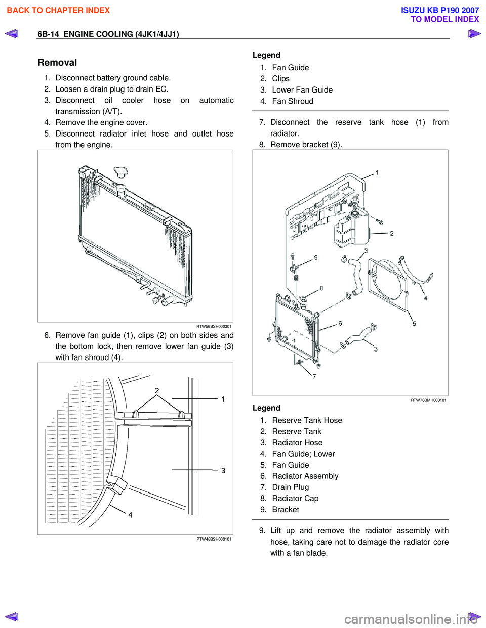
Removal
1. Disconnect battery ground cable.
2. Loosen a drain plug to drain EC.
3. Disconnect oil cooler hose on automatic transmission (A/T).
4. Remove the engine cover.
5. Disconnect radiator inlet hose and outlet hose from the engine.
RTW 56BSH000301
6. Remove fan guide (1), clips (2) on both sides and
the bottom lock, then remove lower fan guide (3)
with fan shroud (4).
PTW 46BSH000101
Legend
1. Fan Guide
2. Clips
3. Lower Fan Guide
4. Fan Shroud
7. Disconnect the reserve tank hose (1) from
radiator.
8. Remove bracket (9).
RTW 76BMH000101
Legend
1. Reserve Tank Hose
2. Reserve Tank
3. Radiator Hose
4. Fan Guide; Lower
5. Fan Guide
6. Radiator Assembly
7. Drain Plug
8. Radiator Cap
9. Bracket
9. Lift up and remove the radiator assembly with
hose, taking care not to damage the radiator core
with a fan blade.
BACK TO CHAPTER INDEX
TO MODEL INDEX
ISUZU KB P190 2007
Page 1539 of 6020
6B-16 ENGINE COOLING (4JK1/4JJ1)
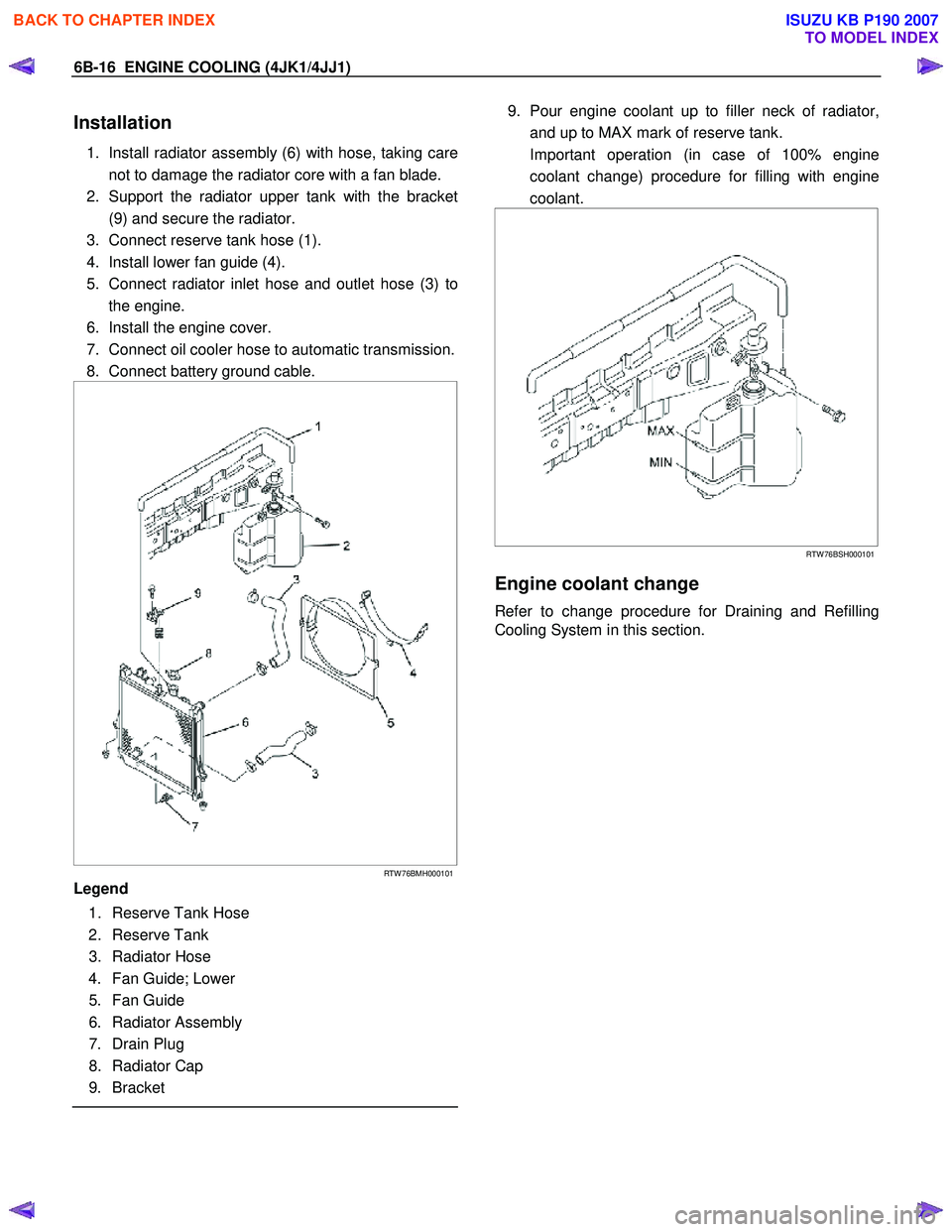
Installation
1. Install radiator assembly (6) with hose, taking care
not to damage the radiator core with a fan blade.
2. Support the radiator upper tank with the bracket (9) and secure the radiator.
3. Connect reserve tank hose (1).
4. Install lower fan guide (4).
5. Connect radiator inlet hose and outlet hose (3) to the engine.
6. Install the engine cover.
7. Connect oil cooler hose to automatic transmission.
8. Connect battery ground cable.
RTW 76BMH000101
Legend
1. Reserve Tank Hose
2. Reserve Tank
3. Radiator Hose
4. Fan Guide; Lower
5. Fan Guide
6. Radiator Assembly
7. Drain Plug
8. Radiator Cap
9. Bracket
9. Pour engine coolant up to filler neck of radiator,
and up to MAX mark of reserve tank.
Important operation (in case of 100% engine coolant change) procedure for filling with engine
coolant.
RTW 76BSH000101
Engine coolant change
Refer to change procedure for Draining and Refilling
Cooling System in this section.
BACK TO CHAPTER INDEX
TO MODEL INDEX
ISUZU KB P190 2007
Page 1663 of 6020

6E-46 ENGINE CONTROL SYSTEM (4JK1/4JJ1)
3Notice:
If an immobilizer system is active the ECM
will disable the fuel injection causing the engine to
stall immediately after starting and energize the
starter cut relay to disable cranking.
Attempt to crank the engine.
Does the engine crank? —
Go to Step 4 Go to Step 5
4 Attempt to start the engine.
Does the engine start and idle? —
Go to Step 6 Go to Engine
Cranks but Does
Not Run
5 Does the scan tool display ECM DTCs P0615,
P0633, P161B or U0167?
—
Go to Applicable DTC Problem is relating
to starting system. Refer to the
applicable
diagnostic chart in starting system
6 Select the DTC display function for the following
control modules: •ECM
• ICU (If so equipped)
• TCM (AISIN A/T only)
Does the scan tool display any DTCs? —
Go to Step 7 Go to Step 11
7 Does the scan tool display DTCs which begin with
U or other control module communication fault
DTCs? —
Go to Applicable
DTC Go to Step 8
8 Does the scan tool display ECM DTCs P0601,
P0602, P0604, P0606 or P1621? —Go to Applicable
DTC Go to Step 9
9 Does the scan tool display ECM DTCs P0562 or
P0563, P156A or P156B? —
Go to Applicable
DTC Go to Step 10
10 Is there any other code in any controller that has
not been diagnosed? —Go to Applicable
DTC Go to Step 11
11 Is the customer’s concern with the automatic
transmission? —Go to Diagnostic
System Check - Transmission
Controls Go to Step 12
12 Is the customer’s concern with the immobilizer
system? —Go to Diagnostic
System Check - Immobilizer
Controls Go to Step 13
13 1. Review the following symptoms.
2. Refer to the applicable symptom diagnostic table:
• Hard Start
• Rough, Unstable, or Incorrect Idle and Stalling
• High Idle Speed
•Cuts Out
• Surges
• Lack of Power, Sluggishness, or Sponginess
• Hesitation, Sag, Stumble
• Abnormal Combustion Noise
• Poor Fuel Economy
• Excessive Smoke (Black Smoke)
• Excessive Smoke (White Smoke)
Did you find and correct the condition? —
System OK Go to Intermittent
Conditions
Step
Action Value(s)Yes No
BACK TO CHAPTER INDEX
TO MODEL INDEX
ISUZU KB P190 2007
Page 1674 of 6020
ENGINE CONTROL SYSTEM (4JK1/4JJ1) 6E-57
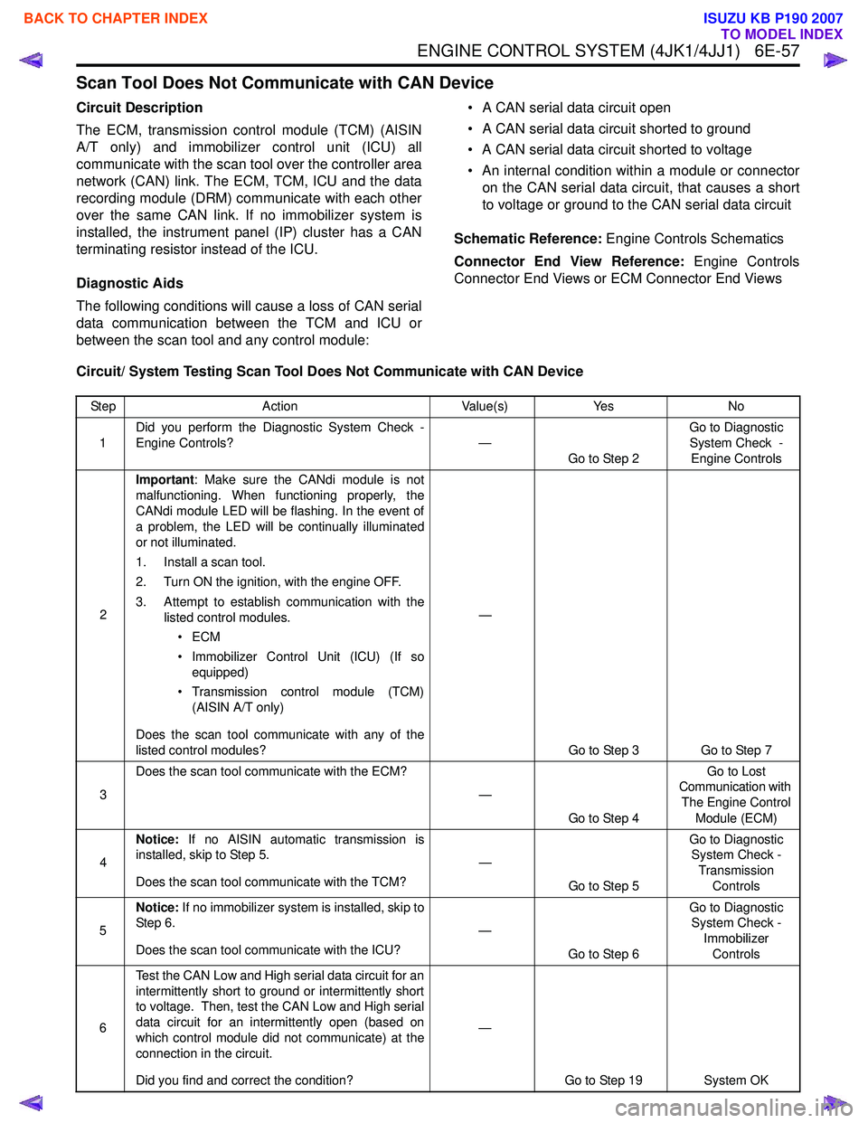
Scan Tool Does Not Communicate with CAN Device
Circuit Description
The ECM, transmission control module (TCM) (AISIN
A/T only) and immobilizer control unit (ICU) all
communicate with the scan tool over the controller area
network (CAN) link. The ECM, TCM, ICU and the data
recording module (DRM) communicate with each other
over the same CAN link. If no immobilizer system is
installed, the instrument panel (IP) cluster has a CAN
terminating resistor instead of the ICU.
Diagnostic Aids
The following conditions will cause a loss of CAN serial
data communication between the TCM and ICU or
between the scan tool and any control module: • A CAN serial data circuit open
• A CAN serial data circuit shorted to ground
• A CAN serial data circuit shorted to voltage
• An internal condition within a module or connector on the CAN serial data circuit, that causes a short
to voltage or ground to the CAN serial data circuit
Schematic Reference: Engine Controls Schematics
Connector End View Reference: Engine Controls
Connector End Views or ECM Connector End Views
Circuit/ System Testing Scan Tool Does Not Communicate with CAN Device
Step Action Value(s)Yes No
1 Did you perform the Diagnostic System Check -
Engine Controls? —
Go to Step 2 Go to Diagnostic
System Check - Engine Controls
2 Important
: Make sure the CANdi module is not
malfunctioning. When functioning properly, the
CANdi module LED will be flashing. In the event of
a problem, the LED will be continually illuminated
or not illuminated.
1. Install a scan tool.
2. Turn ON the ignition, with the engine OFF.
3. Attempt to establish communication with the listed control modules.
•ECM
• Immobilizer Control Unit (ICU) (If so equipped)
• Transmission control module (TCM) (AISIN A/T only)
Does the scan tool communicate with any of the
listed control modules? —
Go to Step 3 Go to Step 7
3 Does the scan tool communicate with the ECM?
—
Go to Step 4 Go to Lost
Communication with
The Engine Control Module (ECM)
4 Notice:
If no AISIN automatic transmission is
installed, skip to Step 5.
Does the scan tool communicate with the TCM? —
Go to Step 5 Go to Diagnostic
System Check -
Transmission Controls
5 Notice:
If no immobilizer system is installed, skip to
Step 6.
Does the scan tool communicate with the ICU? —
Go to Step 6 Go to Diagnostic
System Check -
Immobilizer Controls
6 Test the CAN Low and High serial data circuit for an
intermittently short to ground or intermittently short
to voltage. Then, test the CAN Low and High serial
data circuit for an intermittently open (based on
which control module did not communicate) at the
connection in the circuit.
Did you find and correct the condition? —
Go to Step 19 System OK
BACK TO CHAPTER INDEX
TO MODEL INDEX
ISUZU KB P190 2007