2007 ISUZU KB P190 automatic transmission
[x] Cancel search: automatic transmissionPage 1675 of 6020
6E-58 ENGINE CONTROL SYSTEM (4JK1/4JJ1)
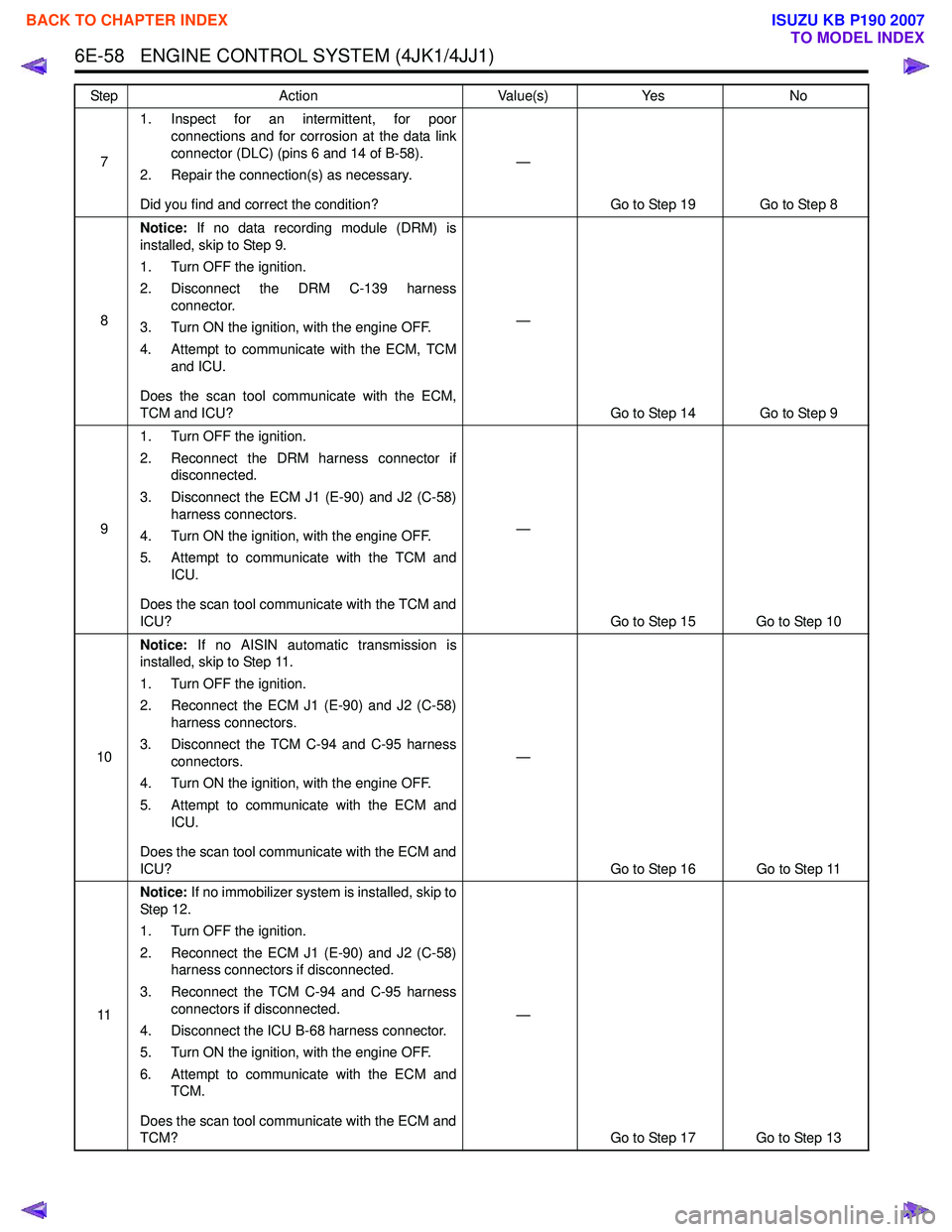
71. Inspect for an intermittent, for poor
connections and for corrosion at the data link
connector (DLC) (pins 6 and 14 of B-58).
2. Repair the connection(s) as necessary.
Did you find and correct the condition? —
Go to Step 19 Go to Step 8
8 Notice:
If no data recording module (DRM) is
installed, skip to Step 9.
1. Turn OFF the ignition.
2. Disconnect the DRM C-139 harness connector.
3. Turn ON the ignition, with the engine OFF.
4. Attempt to communicate with the ECM, TCM and ICU.
Does the scan tool communicate with the ECM,
TCM and ICU? —
Go to Step 14 Go to Step 9
9 1. Turn OFF the ignition.
2. Reconnect the DRM harness connector if disconnected.
3. Disconnect the ECM J1 (E-90) and J2 (C-58) harness connectors.
4. Turn ON the ignition, with the engine OFF.
5. Attempt to communicate with the TCM and ICU.
Does the scan tool communicate with the TCM and
ICU? —
Go to Step 15 Go to Step 10
10 Notice:
If no AISIN automatic transmission is
installed, skip to Step 11.
1. Turn OFF the ignition.
2. Reconnect the ECM J1 (E-90) and J2 (C-58) harness connectors.
3. Disconnect the TCM C-94 and C-95 harness connectors.
4. Turn ON the ignition, with the engine OFF.
5. Attempt to communicate with the ECM and ICU.
Does the scan tool communicate with the ECM and
ICU? —
Go to Step 16 Go to Step 11
11 Notice:
If no immobilizer system is installed, skip to
St ep 1 2.
1. Turn OFF the ignition.
2. Reconnect the ECM J1 (E-90) and J2 (C-58) harness connectors if disconnected.
3. Reconnect the TCM C-94 and C-95 harness connectors if disconnected.
4. Disconnect the ICU B-68 harness connector.
5. Turn ON the ignition, with the engine OFF.
6. Attempt to communicate with the ECM and TCM.
Does the scan tool communicate with the ECM and
TCM? —
Go to Step 17 Go to Step 13
Step
Action Value(s)Yes No
BACK TO CHAPTER INDEX
TO MODEL INDEX
ISUZU KB P190 2007
Page 1789 of 6020
6E-172 ENGINE CONTROL SYSTEM (4JK1/4JJ1)
DTC P0500 (Flash Code 25)
Circuit Description
The vehicle speed sensor (VSS) is used by the ECM
and speedometer, which generates a speed signal from
the transmission output shaft rotational speed or
transfer output shaft rotational speed. The sensor has
the following circuits.
• Ignition voltage circuit
• Low reference circuit
• VSS signal circuit
The VSS uses a hall effect element. It interacts with the
magnetic field created by the rotating magnet and
outputs square wave pulse signal. The ECM calculates
the vehicle speed by the VSS. If the 2WD fitted with
Jatco automatic transmission, VSS signals are sent
from the TCM. If the ECM detects VSS signals are not
generated, this DTC will set.
Condition for Running the DTC • The ignition voltage is more than 9 volts.
• The ignition switch is ON.
• The engine speed is more than 1000 RPM.
• The commanded fuel injection quantity is OFF (accelerator pedal is not depressed). Condition for Setting the DTC
• The ECM detects that the VSS signals are not generated for 5 seconds.
Action Taken When the DTC Sets • The ECM illuminates the MIL when the diagnostic runs and fails. Refer to DTC Type Definitions for
Action Taken When the DTC Sets - Type A.
• The ECM inhibits cruise control.
Condition for Clearing the DTC • Refer to DTC Type Definitions for Condition for Clearing the MIL/ DTC - Type A.
Diagnostic Aids • If an intermittent condition is suspected, refer to Intermittent Conditions in this section.
• Electromagnetic interference in the VSS circuits may set this DTC.
Notice: • If this DTC set, the Vehicle Speed parameter on the scan tool will display 3 km/h (2 MPH).
Schematic Reference: Engine Controls Schematics
Connector End View Reference: Engine Controls
Connector End Views or ECM Connector End Views
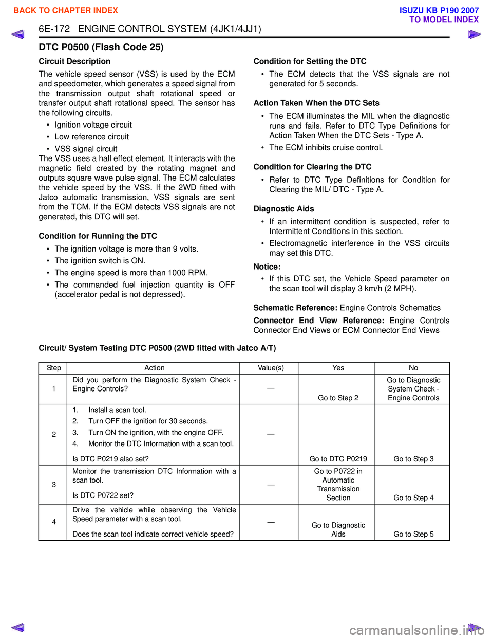
Circuit/ System Testing DTC P0500 (2WD fitted with Jatco A/T)
Step Action Value(s)Yes No
1 Did you perform the Diagnostic System Check -
Engine Controls? —
Go to Step 2 Go to Diagnostic
System Check -
Engine Controls
2 1. Install a scan tool.
2. Turn OFF the ignition for 30 seconds.
3. Turn ON the ignition, with the engine OFF.
4. Monitor the DTC Information with a scan tool.
Is DTC P0219 also set? —
Go to DTC P0219 Go to Step 3
3 Monitor the transmission DTC Information with a
scan tool.
Is DTC P0722 set? —Go to P0722 in
Automatic
Transmission
Section Go to Step 4
4 Drive the vehicle while observing the Vehicle
Speed parameter with a scan tool.
Does the scan tool indicate correct vehicle speed? —
Go to Diagnostic
Aids Go to Step 5
BACK TO CHAPTER INDEX
TO MODEL INDEX
ISUZU KB P190 2007
Page 1793 of 6020
6E-176 ENGINE CONTROL SYSTEM (4JK1/4JJ1)
DTC P0501 (Flash Code 25)
Circuit Description
The vehicle speed sensor (VSS) is used by the ECM
and speedometer, which generates a speed signal from
the transmission output shaft rotational speed or
transfer output shaft rotational speed. The sensor has
the following circuits.
• Ignition voltage feed circuit
• Low reference circuit
• VSS signal circuit
The VSS uses a hall effect element. It interacts with the
magnetic field created by the rotating magnet and
outputs square wave pulse signal. The ECM calculates
the vehicle speed by the VSS. If the 2WD fitted with
Jatco automatic transmission, VSS signals are sent
from the TCM. If the ECM detects VSS signals are
sharply changed, this DTC will set.
Condition for Running the DTC • The ignition voltage is more than 9 volts.
• The ignition switch is ON.
Condition for Setting the DTC • The ECM detects that the VSS signal are changed larger than a predetermined vehicle speed within a
very short calibrated time. Action Taken When the DTC Sets
• The ECM illuminates the MIL when the diagnostic runs and fails. Refer to DTC Type Definitions for
Action Taken When the DTC Sets - Type A.
• The ECM inhibits cruise control.
Condition for Clearing the DTC • Refer to DTC Type Definitions for Condition for Clearing the MIL/ DTC - Type A.
Diagnostic Aids • If an intermittent condition is suspected, refer to Intermittent Conditions in this section.
• Electromagnetic interference in the VSS circuits may set this DTC.
Notice: • If this DTC set, the Vehicle Speed parameter on the scan tool will display 3 km/h (2 MPH).
Schematic Reference: Engine Controls Schematics
Connector End View Reference: Engine Controls
Connector End Views or ECM Connector End Views
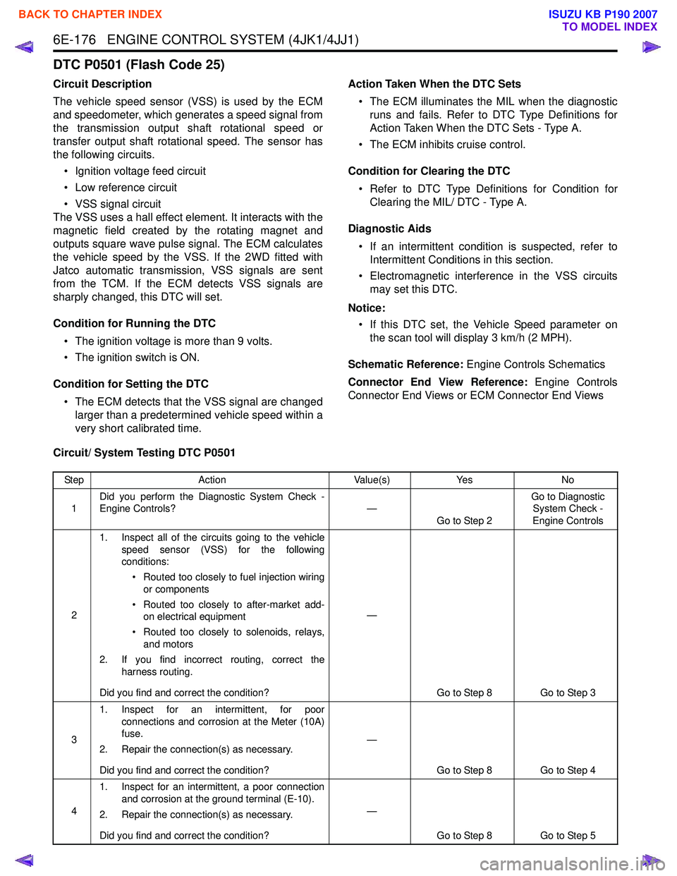
Circuit/ System Testing DTC P0501
Step Action Value(s)Yes No
1 Did you perform the Diagnostic System Check -
Engine Controls? —
Go to Step 2 Go to Diagnostic
System Check -
Engine Controls
2 1. Inspect all of the circuits going to the vehicle
speed sensor (VSS) for the following
conditions:
• Routed too closely to fuel injection wiring or components
• Routed too closely to after-market add- on electrical equipment
• Routed too closely to solenoids, relays, and motors
2. If you find incorrect routing, correct the harness routing.
Did you find and correct the condition? —
Go to Step 8 Go to Step 3
3 1. Inspect for an intermittent, for poor
connections and corrosion at the Meter (10A)
fuse.
2. Repair the connection(s) as necessary.
Did you find and correct the condition? —
Go to Step 8 Go to Step 4
4 1. Inspect for an intermittent, a poor connection
and corrosion at the ground terminal (E-10).
2. Repair the connection(s) as necessary.
Did you find and correct the condition? —
Go to Step 8 Go to Step 5
BACK TO CHAPTER INDEX
TO MODEL INDEX
ISUZU KB P190 2007
Page 1838 of 6020
ENGINE CONTROL SYSTEM (4JK1/4JJ1) 6E-221
DTC P0700 (Flash Code 185)
Circuit Description
The transmission control module (TCM) requests to
illuminate the malfunction indicator lamp (MIL) via a
controller area network (CAN) communication bus to
the ECM when the TCM sets a MIL request DTC(s). If
the ECM detects the MIL illumination request signal,
this DTC will set.
Condition for Running the DTC • DTCs U0001 and U0101 are not set.
• The ignition switch is ON.
Condition for Setting the DTC • The ECM detects that the MIL illumination is requested by the TCM.
Action Taken When the DTC Sets • The ECM illuminates MIL when the diagnostic runs and fails. Refer to DTC Type Definitions for Action
Taken When the DTC Sets - Type A. • The ECM inhibits cruise control.
Condition for Clearing the DTC • Refer to DTC Type Definitions for Condition for Clearing the MIL/ DTC - Type A.
Diagnostic Aids • Under normal conditions if the TCM sets a DTC that requests the MIL to be illuminated, P0700 will
set.
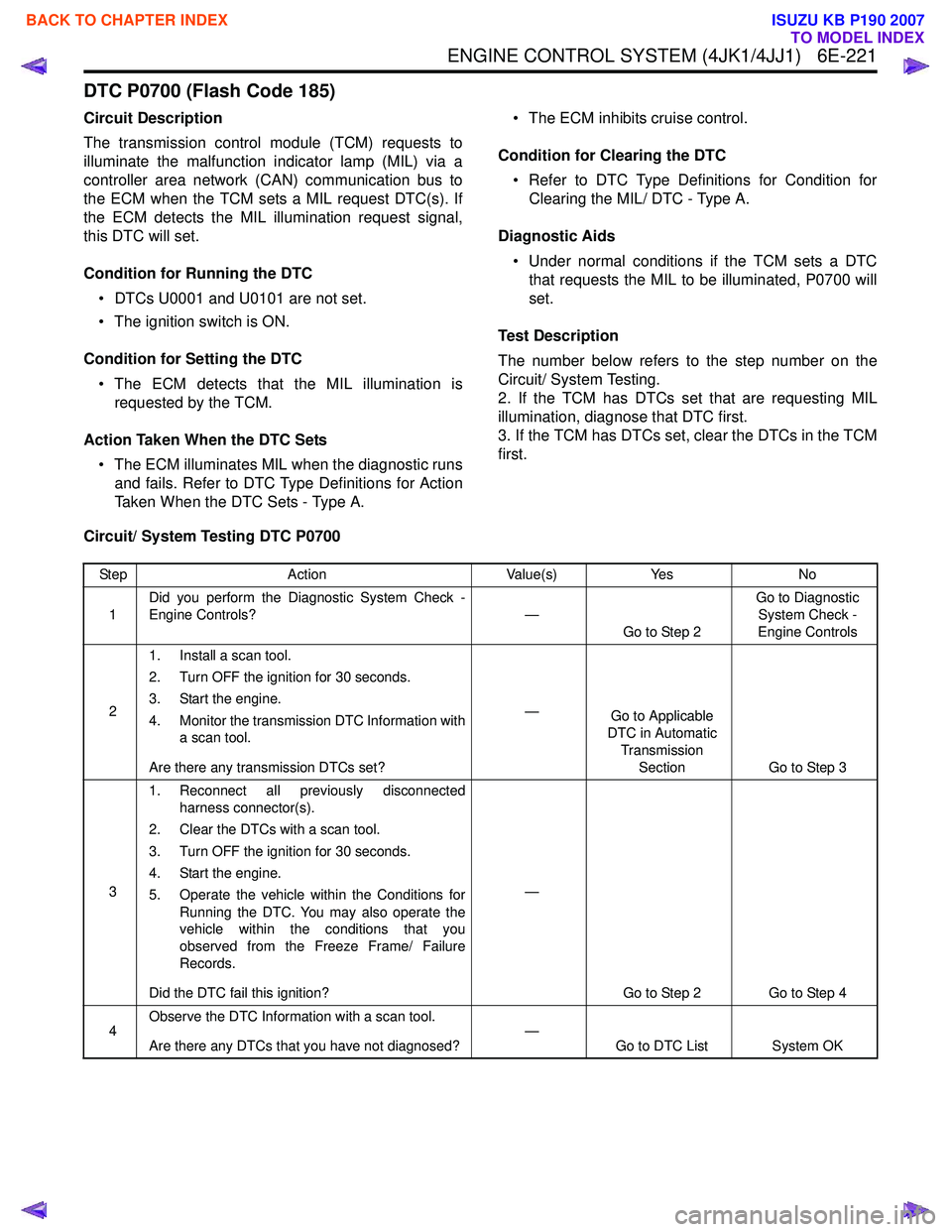
Test Description
The number below refers to the step number on the
Circuit/ System Testing.
2. If the TCM has DTCs set that are requesting MIL
illumination, diagnose that DTC first.
3. If the TCM has DTCs set, clear the DTCs in the TCM
first.
Circuit/ System Testing DTC P0700
Step Action Value(s)Yes No
1 Did you perform the Diagnostic System Check -
Engine Controls? —
Go to Step 2 Go to Diagnostic
System Check -
Engine Controls
2 1. Install a scan tool.
2. Turn OFF the ignition for 30 seconds.
3. Start the engine.
4. Monitor the transmission DTC Information with a scan tool.
Are there any transmission DTCs set? —
Go to Applicable
DTC in Automatic
Transmission Section Go to Step 3
3 1. Reconnect all previously disconnected
harness connector(s).
2. Clear the DTCs with a scan tool.
3. Turn OFF the ignition for 30 seconds.
4. Start the engine.
5. Operate the vehicle within the Conditions for Running the DTC. You may also operate the
vehicle within the conditions that you
observed from the Freeze Frame/ Failure
Records.
Did the DTC fail this ignition? —
Go to Step 2 Go to Step 4
4 Observe the DTC Information with a scan tool.
Are there any DTCs that you have not diagnosed? —
Go to DTC List System OK
BACK TO CHAPTER INDEX
TO MODEL INDEX
ISUZU KB P190 2007
Page 2176 of 6020
6E–6 ENGINE DRIVEABILITY AND EMISSIONS
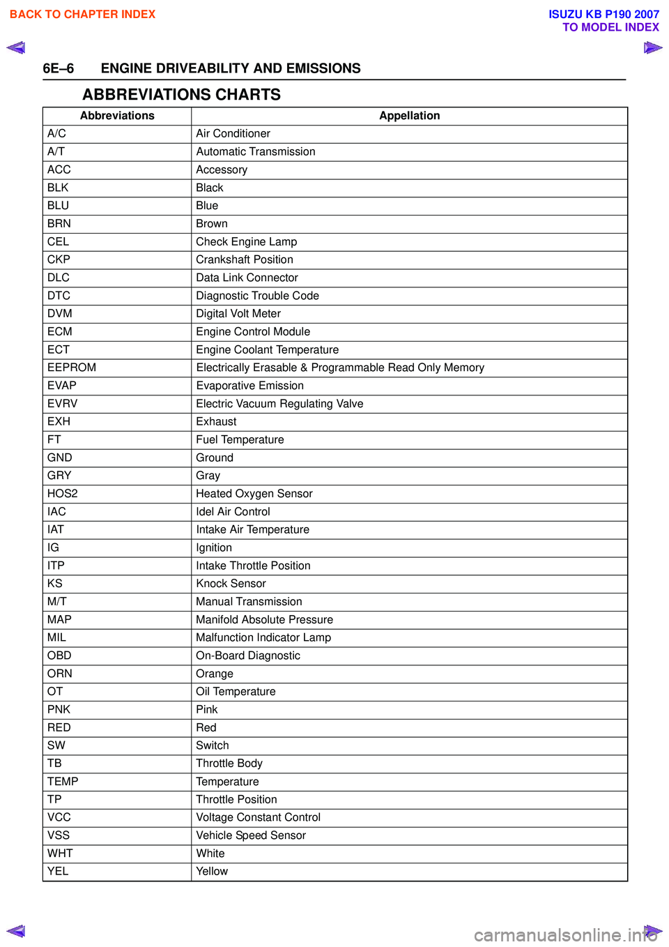
ABBREVIATIONS CHARTS
AbbreviationsAppellation
A/C Air Conditioner
A/T Automatic Transmission
ACC Accessory
BLK Black
BLU Blue
BRN Brown
CEL Check Engine Lamp
CKP Crankshaft Position
DLC Data Link Connector
DTC Diagnostic Trouble Code
DVM Digital Volt Meter
ECM Engine Control Module
ECT Engine Coolant Temperature
EEPROM Electrically Erasable & Programmable Read Only Memory
EVAP Evaporative Emission
EVRV Electric Vacuum Regulating Valve
EXH Exhaust
FT Fuel Temperature
GND Ground
GRY Gray
HOS2 Heated Oxygen Sensor
IAC Idel Air Control
IAT Intake Air Temperature
IG Ignition
ITP Intake Throttle Position
KS Knock Sensor
M/T Manual Transmission
MAP Manifold Absolute Pressure
MIL Malfunction Indicator Lamp
OBD On-Board Diagnostic
ORN Orange
OT Oil Temperature
PNK Pink
RED Red
SW Switch
TB Throttle Body
TEMP Temperature
TP Throttle Position
VCC Voltage Constant Control
VSS Vehicle Speed Sensor
WHT White
YEL Yellow
BACK TO CHAPTER INDEX
TO MODEL INDEX
ISUZU KB P190 2007
Page 2239 of 6020
ENGINE DRIVEABILITY AND EMISSIONS 6E–69
Reading Diagnostic Trouble Codes Using a
Te c h 2
The procedure for reading diagnostic trouble code(s) is
to used a diagnostic Tech 2. When reading DTC(s),
follow instructions supplied by Tech 2 manufacturer.
Clearing Diagnostic Trouble Codes
To clear Diagnostic Trouble Codes (DTCs), use the
Tech 2 “clear DTCs” or “clear information” function.
When clearing DTCs follow instructions supplied by the
Tech 2 manufacturer.
Diagnosis With Tech 2
If no codes are set:
•Refer to F1: Data Display and identify the electrical
faults that are not indicated by trouble code.
• Refer to “SYMPTOM DIAGNOSIS ”.
If codes are set: 1. Record all trouble codes displayed by Tech 2 and check id the codes are intermittent.
2. Clear the codes.
3. Drive the vehicle for a test to reproduce the faulty status.
4. Check trouble codes again using the Tech 2.
5. If no codes is displayed by test driving, the fault is intermittent. In this case, refer to “DIAGNOSIS
AIDS”.
6. If a code is present, refer to DTC Chart for diagnosis.
7. Check trouble codes again using the Tech 2.
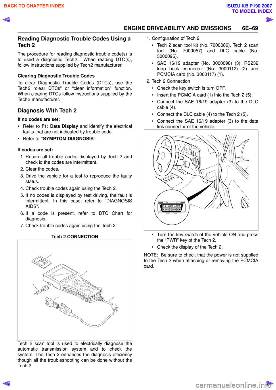
Tech 2 CONNECTION
Tech 2 scan tool is used to electrically diagnose the
automatic transmission system and to check the
system. The Tech 2 enhances the diagnosis efficiency
though all the troubleshooting can be done without the
Te c h 2 . 1. Configuration of Tech 2
• Tech 2 scan tool kit (No. 7000086), Tech 2 scan tool (No. 7000057) and DLC cable (No.
3000095).
• SAE 16/19 adapter (No. 3000098) (3), RS232 loop back connector (No. 3000112) (2) and
PCMCIA card (No. 3000117) (1).
2. Tech 2 Connection
• Check the key switch is turn OFF.
• Insert the PCMCIA card (1) into the Tech 2 (5).
• Connect the SAE 16/19 adapter (3) to the DLC cable (4).
• Connect the DLC cable (4) to the Tech 2 (5).
• Connect the SAE 16/19 adapter (3) to the data link connector of the vehicle.
• Turn the key switch of the vehicle ON and press the “PWR” key of the Tech 2.
• Check the display of the Tech 2.
NOTE: Be sure to check that the power is not supplied
to the Tech 2 when attaching or removing the PCMCIA
card.
BACK TO CHAPTER INDEX
TO MODEL INDEX
ISUZU KB P190 2007
Page 2513 of 6020
Engine Mechanical – V6 Page 6A1–34
2.10 Lower Engine Noise, Regardless of
Engine Speed
NOTE
A cold piston knock which disappears in
approximately 1.5 minutes from start up should
be considered acceptable. A cold engine knock
usually disappears when the specific cylinder’s
secondary ignition circuit is grounded out during
diagnosis.
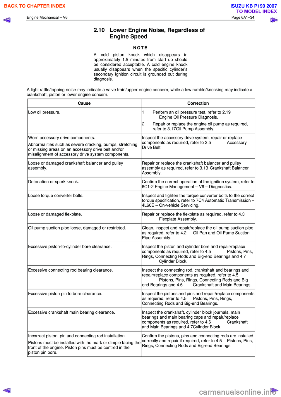
A light rattle/tapping noise may indicate a valve train/upper engine concern, while a low rumble/knocking may indicate a
crankshaft, piston or lower engine concern.
Cause Correction
Low oil pressure. 1 Perform an oil pressure test, refer to 2.19
Engine Oil Pressure Diagnosis.
2 Repair or replace the engine oil pump as required, refer to 3.17 Oil Pump Assembly.
W orn accessory drive components.
Abnormalities such as severe cracking, bumps, stretching
or missing areas on an accessory drive belt and/or
misalignment of accessory drive system components. Inspect the accessory drive system, repair or replace
components as required, refer to 3.5 Accessory
Drive Belt.
Loose or damaged crankshaft balancer and pulley
assembly. Repair or replace the crankshaft balancer and pulley
assembly as required, refer to 3.13 Crankshaft Balancer
Assembly.
Detonation or spark knock. Confirm the correct operation of the ignition system, refer to
6C1-2 Engine Management – V6 – Diagnostics.
Loose torque converter bolts. Inspect and tighten the torque converter bolts to the correct
torque specification, refer to 7C4 Automatic Transmission –
4L60E – On-vehicle Servicing.
Loose or damaged flexplate. Repair or replace the flexplate as required, refer to 4.3
Flexplate Assembly.
Oil pump suction pipe loose, damaged or restricted. Clean, inspect and repair/replace the oil pump suction pipe as required, refer to 4.2 Oil Pan and Oil Pump Suction
Pipe Assembly.
Excessive piston-to-cylinder bore clearance. Inspect the piston and cylinder bore and repair/replace
components as required, refer to 4.5 Pistons, Pins,
Rings, Connecting Rods and Big-end Bearings and 4.7
Cylinder Block.
Excessive connecting rod bearing clearance. Inspect the connecting rod, crankshaft and bearings and
repair/replace components as required, refer to 4.5
Pistons, Pins, Rings, Connecting Rods and Big-
end Bearings and 4.6 Crankshaft and Main Bearings.
Excessive piston pin to bore clearance. Inspect the pistons and pins and repair/replace components
as required, refer to 4.5 Pistons, Pins, Rings,
Connecting Rods and Big-end Bearings.
Excessive crankshaft main bearing clearance. Inspect the crankshaft, cylinder block journals, main
bearings and main bearing caps and repair/replace
components as required, refer to 4.6 Crankshaft
and Main Bearings and 4.7Cylinder Block.
Incorrect piston, pin and connecting rod installation.
Pistons must be installed with the mark or dimple facing the
front of the engine. Piston pins must be centred in the
piston pin bore. Confirm the pistons, pins and connecting rods are installed
correctly and repair if required, refer to 4.5 Pistons, Pins,
Rings, Connecting Rods and Big-end Bearings.
BACK TO CHAPTER INDEX
TO MODEL INDEX
ISUZU KB P190 2007
Page 2669 of 6020

Engine Mechanical – V6 Page 6A1–190
35 Disconnect the harness connector from the transmission, refer to 7B1 Manual Transmission – V6 or 7C1, 2, 3 or 4
for automatic transmission.
36 Remove the left-hand side exhaust manifold upper heat shield (1), (Automatic transmission only).
Figure 6A1 – 330
37 Progressively loosen the seven exhaust manifold attaching bolts (2), working from the outside to the
centre and then remove the bolts.
38 Manoeuvre the exhaust manifold (3), away from the cylinder head.
39 Remove and discard the exhaust manifold to cylinder head gasket.
Figure 6A1 – 331
40 Remove the engine oil level indicator assembly (1), (automatic transmission only).
41 Remove the left-hand side exhaust manifold, (automatic transmission only).
BACK TO CHAPTER INDEX
TO MODEL INDEX
ISUZU KB P190 2007