2007 ISUZU KB P190 automatic transmission
[x] Cancel search: automatic transmissionPage 3259 of 6020
Engine Management – V6 – General Information Page 6C1-1–17
3.9 Serial Data Communication System
The engine control module (ECM) communicates directly with the following control units using the General Motors local
area network (GM LAN) serial data communication protocol:
• Transmission control module (TCM) (if fitted)
• Powertrain interface module (PIM)
The immobiliser control unit (ICU) communicates directly with the PIM using Keyword 2000 serial data communication
protocol. Refer to 11A Immobiliser for further information
As the GM LAN serial data communication protocol is not compatible with the Keyword 2000 serial data communication
protocol, a powertrain interface module (PIM) is integrated to the serial data communication system to perform the
following tasks (Refer to 6E1 Powertrain Interface Module – V6):
• Translate the GM LAN serial data transmitted by the ECM into a Keyword 2000 serial data that can be received
and recognised by the ICU.
• Translate the cruise control switch, automatic transmission power mode switch and 3
rd start switch signal into a GM
LAN serial data that can be received and recognised by the ECM.
3.10 Self Diagnostics System
The ECM constantly performs self-diagnostic tests on the engine management system. W hen the ECM detects a
malfunction, it also stores a diagnostic trouble code (DTC). A stored DTC will identify the problem area(s) and is
designed to assist the technician in rectifying the fault. In addition, DTCs are classified as either Current or History DTC.
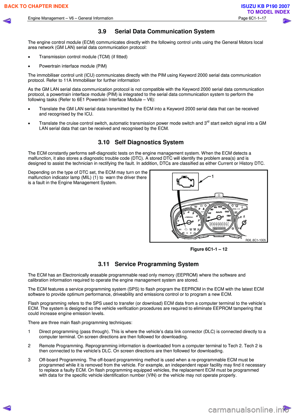
Depending on the type of DTC set, the ECM may turn on the
malfunction indicator lamp (MIL) (1) to warn the driver there
is a fault in the Engine Management System.
Figure 6C1-1 – 12
3.11 Service Programming System
The ECM has an Electronically erasable programmable read only memory (EEPROM) where the software and
calibration information required to operate the engine management system are stored.
The ECM features a service programming system (SPS) to flash program the EEPROM in the ECM with the latest ECM
software to provide optimum performance, driveability and emissions control or to program a new ECM.
Flash programming refers to the SPS used to transfer (or download) ECM data from a computer terminal to the vehicle’s
ECM. The system is designed so the vehicle verification procedures are required to eliminate EEPROM tampering that
could increase engine emission levels.
There are three main flash programming techniques:
1 Direct programming (pass through). This is where the vehicle’s data link connector (DLC) is connected directly to a computer terminal. On screen directions are then followed for downloading.
2 Remote Programming. Reprogramming information is downloaded from a computer terminal to Tech 2. Tech 2 is then connected to the vehicle’s DLC. On screen directions are then followed for downloading.
3 Off-board Programming. The off-board programming method is used when a re-programmable ECM must be programmed while it is removed from the vehicle. For example, an independent repair facility may find it necessary
to replace a faulty ECM. On flash programming equipped vehicles, the replacement ECM must be programmed
with data for the specific vehicle identification number (VIN) or the vehicle may not operate properly.
BACK TO CHAPTER INDEX
TO MODEL INDEX
ISUZU KB P190 2007
Page 3303 of 6020
Engine Management – V6 – Diagnostics Page 6C1-2–25
Checks Actions
Fuel System
• Check the fuel system for the following fault conditions. Refer to 6C Fuel System
– V6 – V6.
• restricted fuel filter,
• incorrect fuel pressure, and
• contaminated fuel.
• Check the operation of the fuel injectors. Refer to 6C1-3 Engine Management –
V6 – Service Operations.
• Perform the fuel injector balance test, refer to 6.3 Fuel Injector Balance
Test in this Section.
• Check the items that can cause an engine to run lean.
• Check the items that cause an engine to run rich.
Ignition System
• Check for an intermittent ignition circuit malfunction.
• Inspect for moisture or corrosion around the spark plug / ignition coil area.
• Test the ignition coil voltage output. Refer to 6C1-3 Engine Management – V6 –
Service Operations.
• Remove and inspect the spark plugs. Refer to 6C1-3 Engine Management – V6 –
Service Operations.
NOTE
If the spark plugs are fouled, determine the cause of the fouling before
replacing the spark plugs. Refer to 6C1-3 Engine Management – V6 –
Service Operations.
• Check for loose ignition coil ground circuit.
Engine Cooling System Check the engine for over-heating. Refer to 6B1 Engine Cooling – V6.
Engine Mechanical Check for the following engine fault conditions. Refer to 6A1 Engine Mechanical – V6.
• low compression, and
• worn valve train components.
Additional Checks
• Check the exhaust system for possible restrictions. Refer to 6F Exhaust System –
V6.
• Electromagnetic interference (EMI) on the crankshaft position (CKP) sensor can
cause an engine misfire condition.
Using Tech 2, monitor the engine speed parameter. A sudden increase in the engine speed parameters without moving the throttle position indicates that an
Electromagnetic Interference fault may be present.
W iring harness routing which may be positioned very close to a high voltage or high current device such as the following may induce EMI:
• secondary ignition components, or
• motors and generators.
Dirty starter motor commutator or brushes can mask the crankshaft position sensor signal.
• Check the torque converter clutch (TCC) operation. A TCC that applies too soon
can cause engine detonation, which will trigger spark retard activity. Refer to 7C1
Automatic Transmission – 4L60E – General Information.
When all diagnosis and repairs are completed, check the system for correct operation.
BACK TO CHAPTER INDEX
TO MODEL INDEX
ISUZU KB P190 2007
Page 3306 of 6020
Engine Management – V6 – Diagnostics Page 6C1-2–28
Checks Actions
Additional Checks
• Check the exhaust system for possible restrictions. Refer to 6F Exhaust System –
V6.
• Electromagnetic interference (EMI) on the crankshaft position (CKP) sensor can
cause an engine misfire condition.
Using Tech 2, monitor the engine speed parameter. A sudden increase in the engine speed parameters without moving the throttle position indicates that an
electromagnetic interference fault may be present.
• W iring harness routing which may be positioned very close to a high voltage or
high current device such as the following may induce EMI:
• secondary ignition components, or
• motors and generators.
When all diagnosis and repairs are completed, check the system for correct operation.
5.6 Detonation / Spark Knock
Description
The engine produces sharp rapid metallic knocks that are more audible during acceleration.
Checks Actions
Preliminary Perform the preliminary checks. Refer to 4.3 Preliminary Checks in this Section.
Sensor System Use Tech 2 to monitor the knock sensor system.
Fuel System
• Check the fuel system for the following fault conditions. Refer to 6C Fuel System
– V6.
• restricted fuel filter,
• incorrect fuel pressure, and
• contaminated fuel.
• Check the operation of the fuel injectors. Refer to 6C1-3 Engine Management –
V6 – Service Operations.
• Perform the fuel injector balance test, refer to 6.3 Fuel Injector Balance
Test in this Section.
• Ensure the fuel tank is filled with petrol that has a minimum octane reading of 92.
• Check for fault conditions that can cause an engine to run lean.
Ignition System Check the spark plugs for proper heat range. Refer to 6C1-3 Engine Management – V6
– Service Operations.
Engine Mechanical • Check the combustion chambers for excessive carbon build-up. Refer to 6A1
Engine Mechanical – V6.
• Check the camshaft timing. Refer to 6A1 Engine Mechanical – V6.
Additional Checks
• Check the torque converter clutch (TCC) operation. The TCC applying too soon
can cause the engine to spark knock. Refer to 7C2 Automatic Transmission –
4L60E – Electrical Diagnosis.
When all diagnosis and repairs are completed, check the system for correct operation.
5.7 Dieseling, Run-on
Description
The engine continues to run after the ignition is switched off but runs very roughly and then stalls.
BACK TO CHAPTER INDEX
TO MODEL INDEX
ISUZU KB P190 2007
Page 3312 of 6020
Engine Management – V6 – Diagnostics Page 6C1-2–34
Checks Actions
Additional Checks
• Check the exhaust system for possible restrictions. Refer to 6F Exhaust System –
V6.
• Electromagnetic interference (EMI) on the crankshaft position (CKP) sensor can
cause an engine misfire condition.
Using Tech 2, monitor the engine speed parameter. A sudden increase in the engine speed parameters without moving the throttle position indicates that an
Electromagnetic Interference fault may be present.
W iring harness routing which may be positioned very close to a high voltage or high current device such as the following may induce EMI:
• secondary ignition components, and
• motors and generators.
• Check the torque converter clutch (TCC) operation. A TCC that applies too soon
can cause engine detonation, which will trigger spark retard activity. Refer to 7C2
Automatic Transmission – 4L60E – Electrical Diagnosis.
• Test for other TCM related faults that may cause the transmission to operate in
the default mode. Refer to 7C2 Automatic Transmission – 4L60E – Electrical
Diagnosis.
• Check for transmission mechanical faults such as slipping clutch. Refer to 7C3
Automatic Transmission – 4L60E – Hydraulic and Mechanical Diagnosis.
• Check the brake system including the parking brake for sticking or incorrect
operation.
When all diagnosis and repairs are completed, check the system for correct operation.
5.12 Rough, Unstable, Incorrect Idle or
Stalling
Description
Engine idle speed fluctuates causing the engine to run unevenly. If the engine idle speed drops too low, the engine may
stall.
Checks Actions
Preliminary • Perform the preliminary checks. Refer to 4.3 Preliminary Checks in this
Section.
• Check the air filter element and intake air ducts for blockages.
Sensor / System
• Check the throttle actuator control (TAC) system. Refer to 6C1-3 Engine
Management – V6 – Service Operations.
• Check the air intake system and crankcase for air leaks. Refer to 6C1-3 Engine
Management – V6 – Service Operations.
• Check the PCV System for correct operation. Refer to 6A1 Engine Mechanical –
V6.
• Use Tech 2 to monitor the knock sensor system for excessive spark retard
activity. Check for items that cause spark retard activity.
• Using Tech 2, check the heated oxygen sensor (HO2s) operating parameters.
The HO2s sensor should respond quickly to different throttle positions.
BACK TO CHAPTER INDEX
TO MODEL INDEX
ISUZU KB P190 2007
Page 3313 of 6020
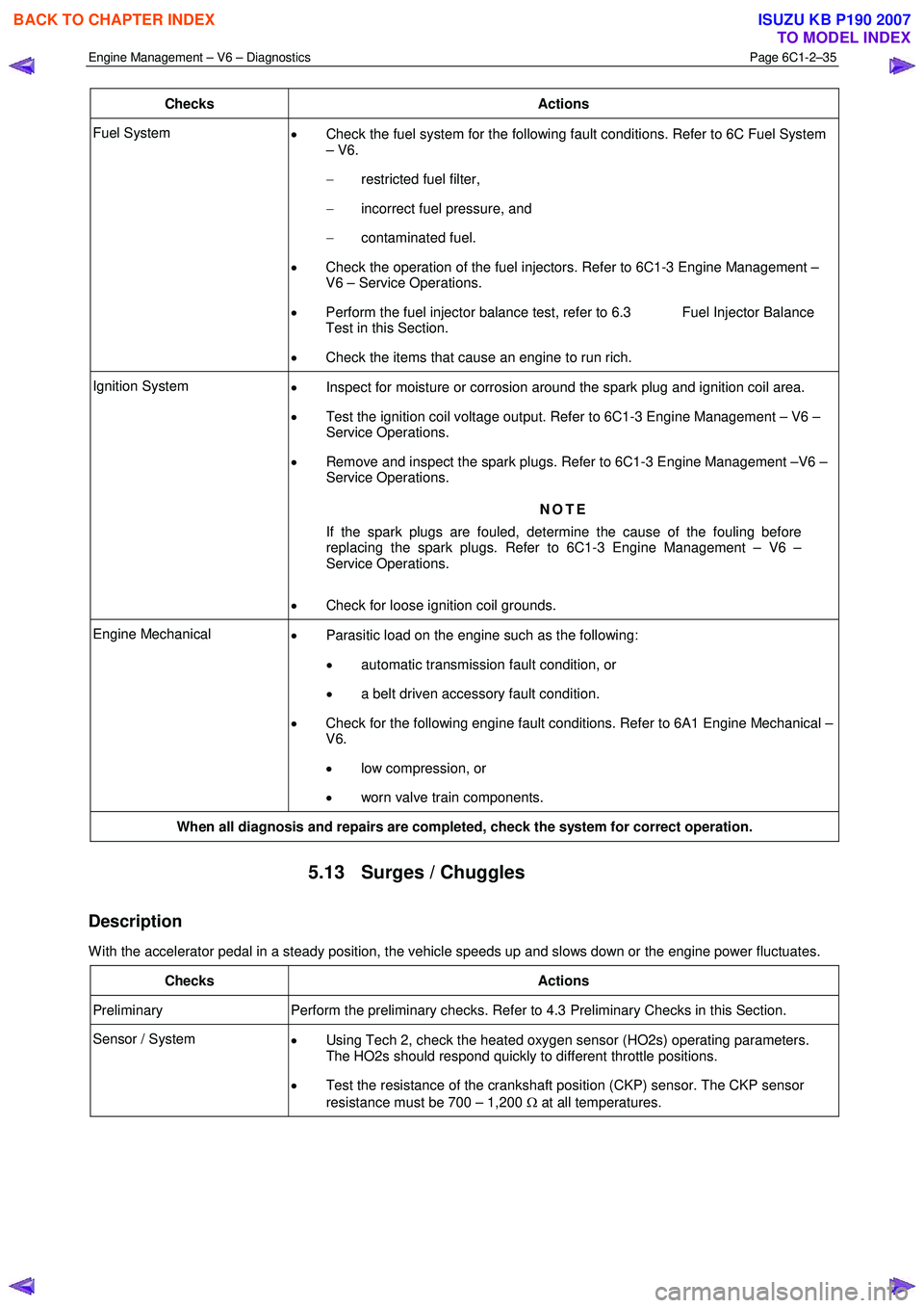
Engine Management – V6 – Diagnostics Page 6C1-2–35
Checks Actions
Fuel System
• Check the fuel system for the following fault conditions. Refer to 6C Fuel System
– V6.
− restricted fuel filter,
− incorrect fuel pressure, and
− contaminated fuel.
• Check the operation of the fuel injectors. Refer to 6C1-3 Engine Management –
V6 – Service Operations.
• Perform the fuel injector balance test, refer to 6.3 Fuel Injector Balance
Test in this Section.
• Check the items that cause an engine to run rich.
Ignition System
• Inspect for moisture or corrosion around the spark plug and ignition coil area.
• Test the ignition coil voltage output. Refer to 6C1-3 Engine Management – V6 –
Service Operations.
• Remove and inspect the spark plugs. Refer to 6C1-3 Engine Management –V6 –
Service Operations.
NOTE
If the spark plugs are fouled, determine the cause of the fouling before
replacing the spark plugs. Refer to 6C1-3 Engine Management – V6 –
Service Operations.
• Check for loose ignition coil grounds.
Engine Mechanical
• Parasitic load on the engine such as the following:
• automatic transmission fault condition, or
• a belt driven accessory fault condition.
• Check for the following engine fault conditions. Refer to 6A1 Engine Mechanical –
V6.
• low compression, or
• worn valve train components.
When all diagnosis and repairs are completed, check the system for correct operation.
5.13 Surges / Chuggles
Description
W ith the accelerator pedal in a steady position, the vehicle speeds up and slows down or the engine power fluctuates.
Checks Actions
Preliminary Perform the preliminary checks. Refer to 4.3 Preliminary Checks in this Section.
Sensor / System
• Using Tech 2, check the heated oxygen sensor (HO2s) operating parameters.
The HO2s should respond quickly to different throttle positions.
• Test the resistance of the crankshaft position (CKP) sensor. The CKP sensor
resistance must be 700 – 1,200 Ω at all temperatures.
BACK TO CHAPTER INDEX
TO MODEL INDEX
ISUZU KB P190 2007
Page 3314 of 6020
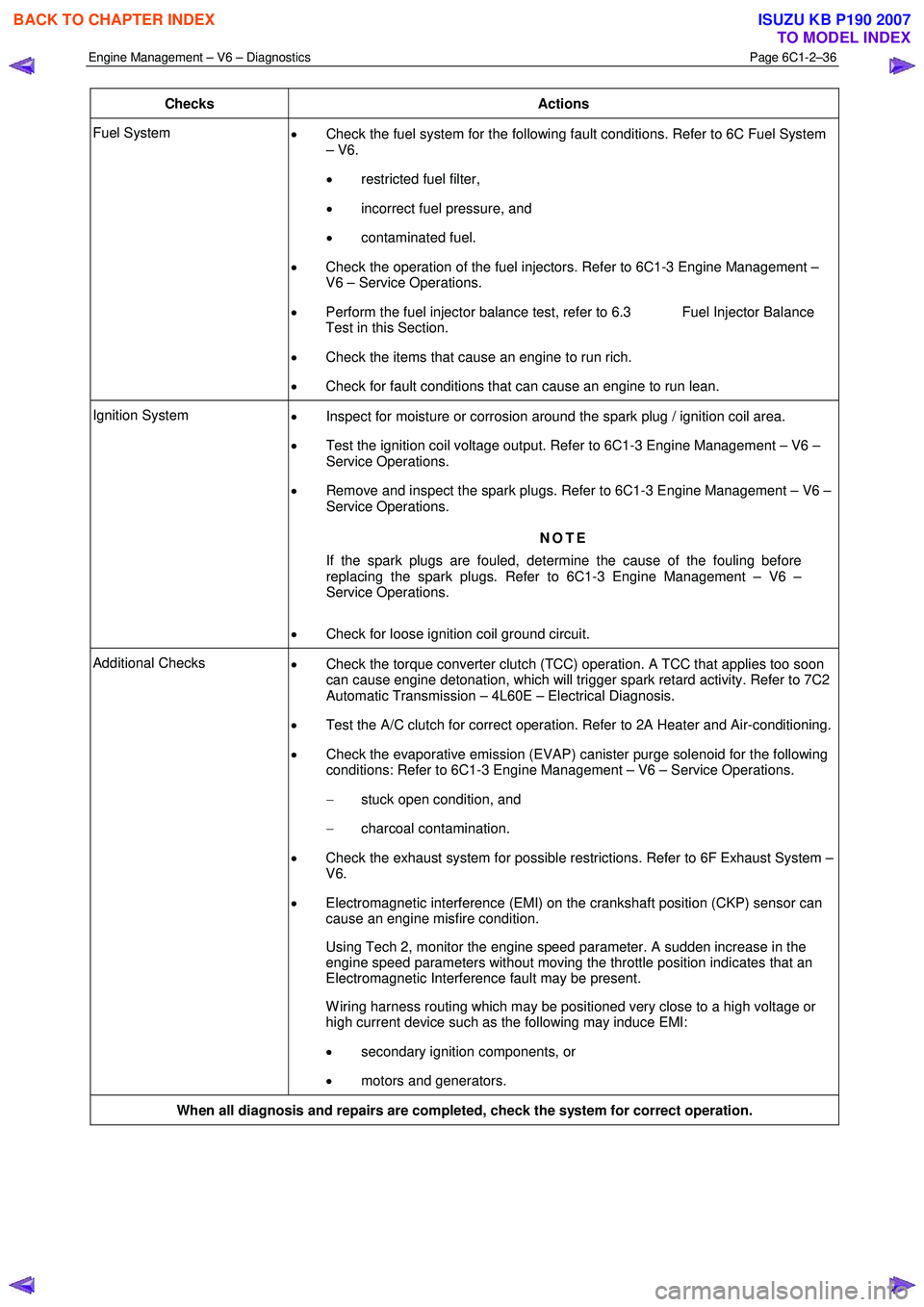
Engine Management – V6 – Diagnostics Page 6C1-2–36
Checks Actions
Fuel System
• Check the fuel system for the following fault conditions. Refer to 6C Fuel System
– V6.
• restricted fuel filter,
• incorrect fuel pressure, and
• contaminated fuel.
• Check the operation of the fuel injectors. Refer to 6C1-3 Engine Management –
V6 – Service Operations.
• Perform the fuel injector balance test, refer to 6.3 Fuel Injector Balance
Test in this Section.
• Check the items that cause an engine to run rich.
• Check for fault conditions that can cause an engine to run lean.
Ignition System
• Inspect for moisture or corrosion around the spark plug / ignition coil area.
• Test the ignition coil voltage output. Refer to 6C1-3 Engine Management – V6 –
Service Operations.
• Remove and inspect the spark plugs. Refer to 6C1-3 Engine Management – V6 –
Service Operations.
NOTE
If the spark plugs are fouled, determine the cause of the fouling before
replacing the spark plugs. Refer to 6C1-3 Engine Management – V6 –
Service Operations.
• Check for loose ignition coil ground circuit.
Additional Checks
• Check the torque converter clutch (TCC) operation. A TCC that applies too soon
can cause engine detonation, which will trigger spark retard activity. Refer to 7C2
Automatic Transmission – 4L60E – Electrical Diagnosis.
• Test the A/C clutch for correct operation. Refer to 2A Heater and Air-conditioning.
• Check the evaporative emission (EVAP) canister purge solenoid for the following
conditions: Refer to 6C1-3 Engine Management – V6 – Service Operations.
− stuck open condition, and
− charcoal contamination.
• Check the exhaust system for possible restrictions. Refer to 6F Exhaust System –
V6.
• Electromagnetic interference (EMI) on the crankshaft position (CKP) sensor can
cause an engine misfire condition.
Using Tech 2, monitor the engine speed parameter. A sudden increase in the engine speed parameters without moving the throttle position indicates that an
Electromagnetic Interference fault may be present.
W iring harness routing which may be positioned very close to a high voltage or high current device such as the following may induce EMI:
• secondary ignition components, or
• motors and generators.
When all diagnosis and repairs are completed, check the system for correct operation.
BACK TO CHAPTER INDEX
TO MODEL INDEX
ISUZU KB P190 2007
Page 3324 of 6020
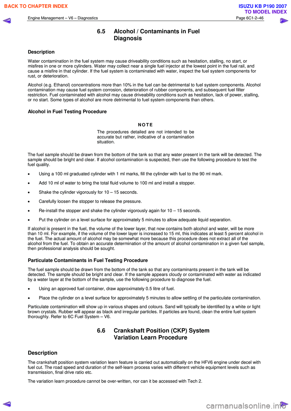
Engine Management – V6 – Diagnostics Page 6C1-2–46
6.5 Alcohol / Contaminants in Fuel
Diagnosis
Description
W ater contamination in the fuel system may cause driveability conditions such as hesitation, stalling, no start, or
misfires in one or more cylinders. W ater may collect near a single fuel injector at the lowest point in the fuel rail, and
cause a misfire in that cylinder. If the fuel system is contaminated with water, inspect the fuel system components for
rust, or deterioration.
Alcohol (e.g. Ethanol) concentrations more than 10% in the fuel can be detrimental to fuel system components. Alcohol
contamination may cause fuel system corrosion, deterioration of rubber components, and subsequent fuel filter
restriction. Fuel contaminated with alcohol may cause driveability conditions such as hesitation, lack of power, stalling,
or no start. Some types of alcohol are more detrimental to fuel system components than others.
Alcohol in Fuel Testing Procedure
NOTE
The procedures detailed are not intended to be
accurate but rather, indicative of a contamination
situation.
The fuel sample should be drawn from the bottom of the tank so that any water present in the tank will be detected. The
sample should be bright and clear. If alcohol contamination is suspected, then use the following procedure to test the
fuel quality.
• Using a 100 ml graduated cylinder with 1 ml marks, fill the cylinder with fuel to the 90 ml mark.
• Add 10 ml of water to bring the total fluid volume to 100 ml and install a stopper.
• Shake the cylinder vigorously for 10 – 15 seconds.
• Carefully loosen the stopper to release the pressure.
• Re-install the stopper and shake the cylinder vigorously again for 10 – 15 seconds.
• Put the cylinder on a level surface for approximately 5 minutes to allow adequate liquid separation.
If alcohol is present in the fuel, the volume of the lower layer, that now contains both alcohol and water, will be more
than 10 ml. For example, if the volume of the lower layer is increased to 15 ml, this indicates at least 5 percent alcohol in
the fuel. The actual amount of alcohol may be somewhat more because this procedure does not extract all of the
alcohol from the fuel. To obtain an accurate determination of the amount of alcohol contamination in a given fuel sample,
then professional analysis should be sought.
Particulate Contaminants in Fuel Testing Procedure
The fuel sample should be drawn from the bottom of the tank so that any contaminants present in the tank will be
detected. The sample should be bright and clear. If the sample appears cloudy or contaminated with water as indicated
by a water layer at the bottom of the sample, use the following procedure to diagnose the fuel.
• Using an approved fuel container, draw approximately 0.5 litre of fuel.
• Place the cylinder on a level surface for approximately 5 minutes to allow settling of the particulate contamination.
Particulate contamination will show up in various shapes and colours. Sand will typically be identified by a white or light
brown crystals. Rubber will appear as black and irregular particles. If particles are found, clean the entire fuel system
thoroughly. Refer to 6C Fuel System – V6.
6.6 Crankshaft Position (CKP) System
Variation Learn Procedure
Description
The crankshaft position system variation learn feature is carried out automatically on the HFV6 engine under decel with
fuel cut. The road speed and duration of the self-learn process varies with different vehicle equipment levels such as
transmission, final drive ratio etc.
The variation learn procedure cannot be over-written, nor can it be accessed with Tech 2.
BACK TO CHAPTER INDEX
TO MODEL INDEX
ISUZU KB P190 2007
Page 3439 of 6020
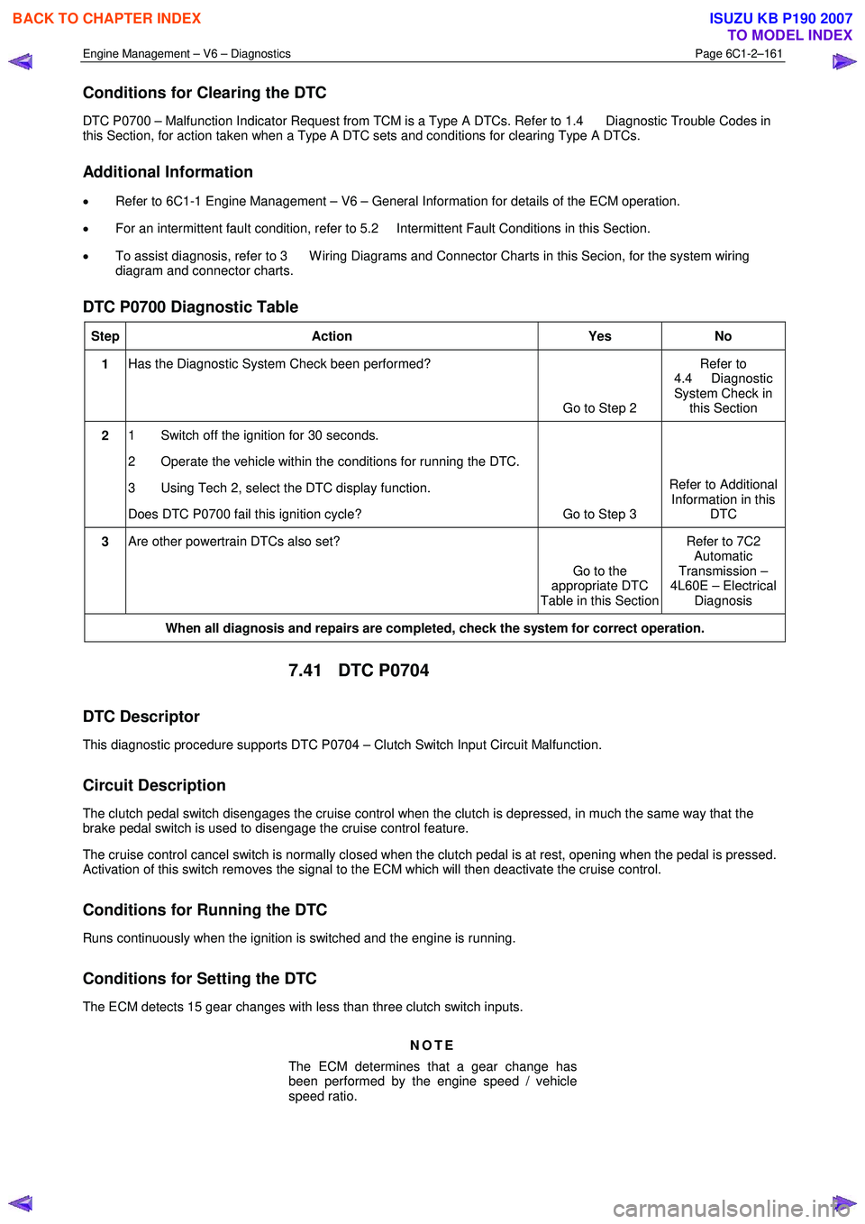
Engine Management – V6 – Diagnostics Page 6C1-2–161
Conditions for Clearing the DTC
DTC P0700 – Malfunction Indicator Request from TCM is a Type A DTCs. Refer to 1.4 Diagnostic Trouble Codes in
this Section, for action taken when a Type A DTC sets and conditions for clearing Type A DTCs.
Additional Information
• Refer to 6C1-1 Engine Management – V6 – General Information for details of the ECM operation.
• For an intermittent fault condition, refer to 5.2 Intermittent Fault Conditions in this Section.
• To assist diagnosis, refer to 3 W iring Diagrams and Connector Charts in this Secion, for the system wiring
diagram and connector charts.
DTC P0700 Diagnostic Table
Step Action Yes No
1 Has the Diagnostic System Check been performed?
Go to Step 2 Refer to
4.4 Diagnostic
System Check in this Section
2 1 Switch off the ignition for 30 seconds.
2 Operate the vehicle within the conditions for running the DTC.
3 Using Tech 2, select the DTC display function.
Does DTC P0700 fail this ignition cycle? Go to Step 3 Refer to Additional
Information in this DTC
3 Are other powertrain DTCs also set?
Go to the
appropriate DTC
Table in this Section Refer to 7C2
Automatic
Transmission –
4L60E – Electrical Diagnosis
When all diagnosis and repairs are completed, check the system for correct operation.
7.41 DTC P0704
DTC Descriptor
This diagnostic procedure supports DTC P0704 – Clutch Switch Input Circuit Malfunction.
Circuit Description
The clutch pedal switch disengages the cruise control when the clutch is depressed, in much the same way that the
brake pedal switch is used to disengage the cruise control feature.
The cruise control cancel switch is normally closed when the clutch pedal is at rest, opening when the pedal is pressed.
Activation of this switch removes the signal to the ECM which will then deactivate the cruise control.
Conditions for Running the DTC
Runs continuously when the ignition is switched and the engine is running.
Conditions for Setting the DTC
The ECM detects 15 gear changes with less than three clutch switch inputs.
NOTE
The ECM determines that a gear change has
been performed by the engine speed / vehicle
speed ratio.
BACK TO CHAPTER INDEX
TO MODEL INDEX
ISUZU KB P190 2007