2007 ISUZU KB P190 automatic transmission
[x] Cancel search: automatic transmissionPage 3656 of 6020
Battery Page 6D1-3–16
NOTE
Charging a battery at higher current rates can
significantly reduce the life of the battery.
Charge Rate Initial Current Maximum Time Required
Slow charge 4 A 24 hours
Fast charge 35 A 2 hours
6 After a few minutes, check the colour and specific gravity of the electrolyte. Refer to 3.3 Hydrometer Test.
7 Monitor the electrolyte temperature while the battery is charging. If the electrolyte temperature reaches 55 °C:
a switch the charging current off,
b allow the battery to cool,
c reduce the charging current, and
d restart charging the battery.
NOTE
For the best results, charge the battery with the
electrolyte and plates at room temperature. An
extremely cold battery may not appear to accept
current for several hours after starting the battery
charger. If the battery does not appear to accept
charge after several hours replace the battery.
8 For slow charging check the voltage and specific gravity each hour or more regularly for fast charging. Stop the charging when there is no change in voltage or electrolyte specific gravity over three checks.
9 If the battery was fast charged connect the battery to a slow-charger for a few hours to bring the battery to the fully charged condition. Ensure the last few hours of charge do not exceed 1 A.
10 Tighten the filler caps. Ensure they are secure.
11 Install the battery in the vehicle. Refer to 4.1 Battery.
4.3 Emergency Jump Starting Procedure
Safety Precautions
• Read and obey the general safety precautions for working with batteries, refer to 2 Safety Precautions.
• Do not allow the vehicles to touch each other during the jump starting procedure.
• Ensure the assisting vehicle battery has the same voltage rating and connects negative to ground. If this is not the
case, serious injury and damage to electrical equipment can result.
• Do not push or tow the vehicle to start it. Damage can result when unburnt fuel reaches the catalytic converter and
ignites.
• Do not start the vehicle using a fast charger.
• W hen using jumper leads, treat both the booster battery and the discharged battery with care.
• Do not allow sparks, flame or smoking near the battery.
• Ensure that metal tools or jumper cables do not simultaneously contact the battery positive terminal and any other
metal part of the vehicle.
Jump Starting Procedure
1 Position the assisting vehicle so the batteries of both vehicles are close together, refer to Figure 6D1-3 – 10.
2 Apply the park brake on both vehicles.
3 Ensure that P (park) is selected for automatic transmission and N (neutral) is selected for manual transmissions.
BACK TO CHAPTER INDEX
TO MODEL INDEX
ISUZU KB P190 2007
Page 3662 of 6020
Powertrain Interface Module – V6 Page 6E1–1
6E1
Powertrain Interface Module – V6
ATTENTION
Before performing any service operation or other procedure described in this Section, refer to 1.2 Warning
Caution and Notes for correct workshop practices with regard to safety and / or property damage.
1 General Information ............................................................................................................ ...................6
1.1 General Description ............................................................................................................ ................................... 6
Serial Data Communication .................................................................................................................................. 6
Serial Data Layout.................................................................................................................................................. 8
1.2 Warning Caution and Notes .................................................................................................................................. 8
Definition of WARNING, CAUTION and NOTE Statements ............................................................................. .... 8
2 Component Location............................................................................................................................10
2.1 Engine Compartment............................................................................................................. .............................. 10
2.2 Interior................................................................................................................................................................... 11
3 Component Description and Operation ............................................................................................ .12
3.1 Powertrain Interface Module ............................................................................................................................... 12
3.2 Powertrain Interface Module Gateway Components ................................................................................. ....... 13
Engine Control Module........................................................................................................................................ 13
Immobiliser Control Unit ..................................................................................................................................... 13
Automatic Transmission Control Module .......................................................................................... ................ 13
3.3 Powertrain Interface Module Direct Input Switches.............................................................................. ............ 14
Cruise Control Switch.......................................................................................................................................... 14
Power Mode Switch – Automatic Transmission..................................................................................... ........... 14
3rd Start Switch – Automatic Transmission ....................................................................................................... 14
4 Diagnostics ...........................................................................................................................................15
4.1 Diagnostic General Descriptions................................................................................................ ........................ 15
Diagnostic Trouble Code (DTC) Tables........................................................................................... ................... 15
Diagnostic Trouble Codes (DTCs) ...................................................................................................................... 15
Tech 2 PIM Diagnostic Tests............................................................................................................................... 16
5 GM LAN Serial Communication Circuit ............................................................................................ ..17
6 Wiring Diagram and Connector Chart ................................................................................................18
6.1 Wiring Diagrams .................................................................................................................................................. 18
6.2 Connector Chart................................................................................................................................................... 20
6.3 Connector Information .......................................................................................................... .............................. 21
PIM Connector Pin Specifications ............................................................................................... ....................... 21
7 Diagnostics Starting Point ..................................................................................................................24
7.1 Diagnostic Requirements, Precautions and Preliminary Checks .................................................................... 24
Basic Knowledge Required ................................................................................................................................. 24
Basic Diagnostic Tools Required ................................................................................................ ....................... 24
Diagnostic Precautions ....................................................................................................................................... 24
Preliminary Checks.............................................................................................................................................. 25
7.2 Diagnostic System Check ........................................................................................................ ........................... 25
7.3 Powertrain Interface Module – Module Communication Check Failure Diagnostic Table............................. 27
BACK TO CHAPTER INDEX
TO MODEL INDEX
ISUZU KB P190 2007
Page 3667 of 6020
Powertrain Interface Module – V6 Page 6E1–6
1 General Information
A powertrain interface module (PIM) is fitted that incorporates the following functionality:
• Communication protocol between the engine control module (ECM) and transmission control module (TCM) is
General Motors Local Area Network (GM LAN).
• Communication protocol between the PIM and immobiliser control unit is keyword 2000.
• ECM to PIM and PIM to immobiliser control unit (ICU) authentication for vehicle security.
• The following switches, where fitted, input directly into the PIM:
• Automatic transmission power mode switch.
• Automatic transmission 3
rd gear start switch.
• Cruise control switch.
1.1 General Description
Serial Data Communication
The various electronic control modules communicate with each other through the serial data bus. The ECM and TCM
communicate on the serial data bus using the GM LAN communication protocol. Figure 6E1 – 2 shows the serial data
layout.
NOTE
Serial data components shown in Figure 6E1 – 2
will vary depending on vehicle options.
Bus
A bus is a physical circuit or circuits which provides a communication path between two or more control modules.
GM LAN Serial Data Bus
The GM LAN bus is a two wire circuit (1), refer to Figure 6E1 – 1. The GM LAN bus circuits are terminated with cut-off
resistors (2) which are located inside the two control modules at either end of the bus circuit. The purpose of these cut-off
resistors is to prevent data from returning as an echo after reaching the end of the GM LAN bus circuit.
NOTE
• For illustration purposes, the cut-off resistors
are shown outside of the control modules.
• The two control modules with the cut-off
resistors are the PIM and the ECM.
BACK TO CHAPTER INDEX
TO MODEL INDEX
ISUZU KB P190 2007
Page 3672 of 6020
Powertrain Interface Module – V6 Page 6E1–11
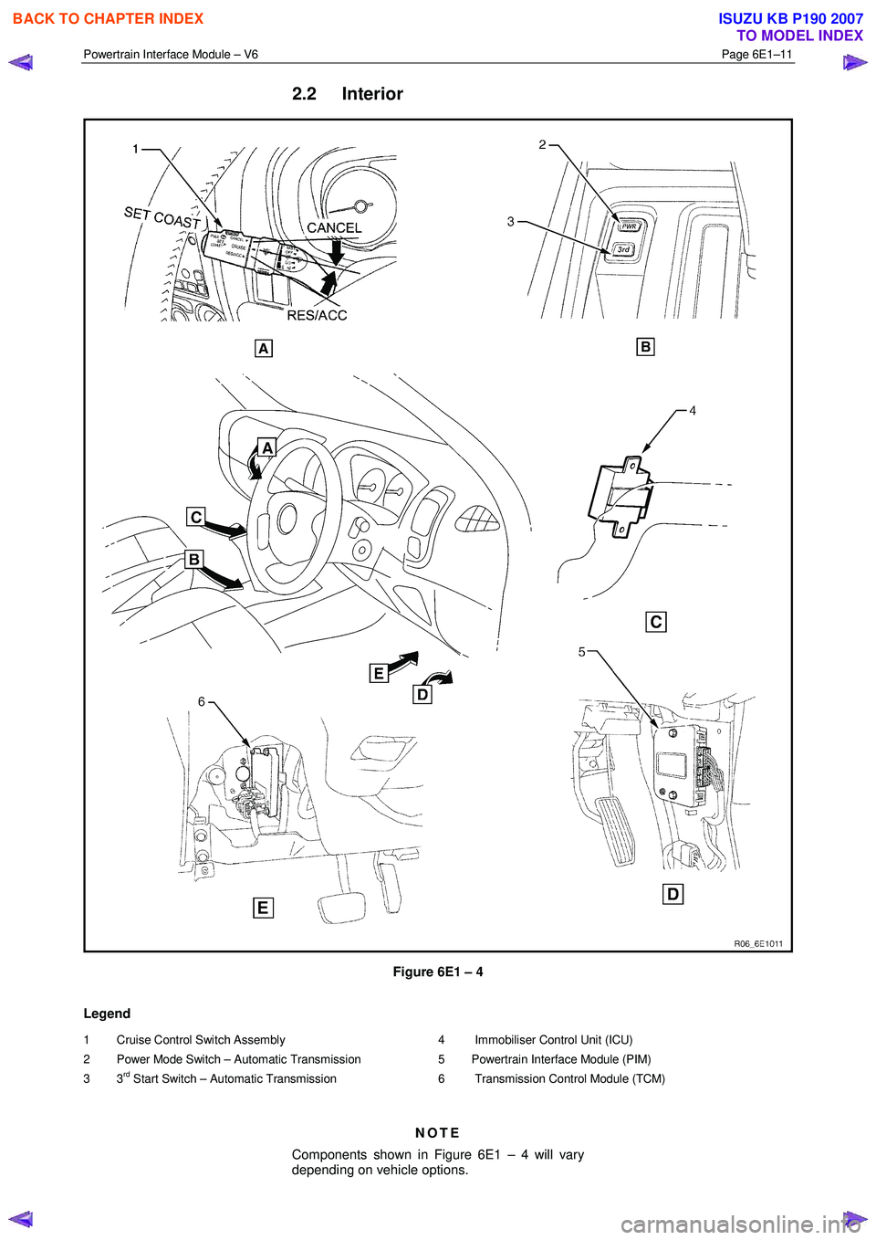
2.2 Interior
Figure 6E1 – 4
Legend
1 Cruise Control Switch Assembly
2 Power Mode Switch – Automatic Transmission
3 3
rd Start Switch – Automatic Transmission
4 Immobiliser Control Unit (ICU)
5 Powertrain Interface Module (PIM)
6 Transmission Control Module (TCM)
NOTE
Components shown in Figure 6E1 – 4 will vary
depending on vehicle options.
BACK TO CHAPTER INDEX
TO MODEL INDEX
ISUZU KB P190 2007
Page 3673 of 6020
Powertrain Interface Module – V6 Page 6E1–12
3 Component Description and
Operation
3.1 Powertrain Interface Module
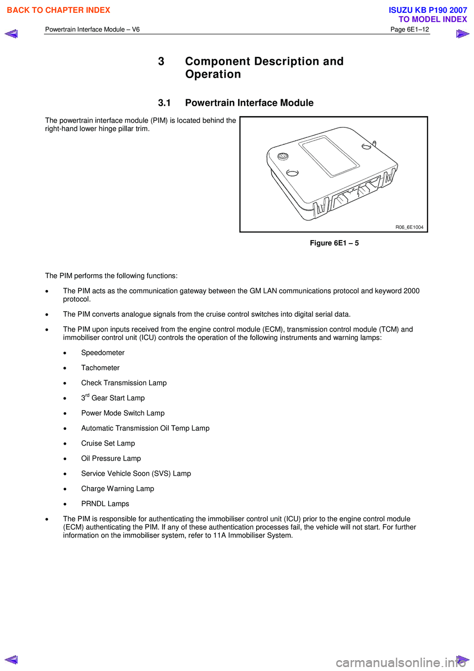
The powertrain interface module (PIM) is located behind the
right-hand lower hinge pillar trim.
Figure 6E1 – 5
The PIM performs the following functions:
• The PIM acts as the communication gateway between the GM LAN communications protocol and keyword 2000
protocol.
• The PIM converts analogue signals from the cruise control switches into digital serial data.
• The PIM upon inputs received from the engine control module (ECM), transmission control module (TCM) and
immobiliser control unit (ICU) controls the operation of the following instruments and warning lamps:
• Speedometer
• Tachometer
• Check Transmission Lamp
• 3
rd Gear Start Lamp
• Power Mode Switch Lamp
• Automatic Transmission Oil Temp Lamp
• Cruise Set Lamp
• Oil Pressure Lamp
• Service Vehicle Soon (SVS) Lamp
• Charge W arning Lamp
• PRNDL Lamps
• The PIM is responsible for authenticating the immobiliser control unit (ICU) prior to the engine control module
(ECM) authenticating the PIM. If any of these authentication processes fail, the vehicle will not start. For further
information on the immobiliser system, refer to 11A Immobiliser System.
BACK TO CHAPTER INDEX
TO MODEL INDEX
ISUZU KB P190 2007
Page 3674 of 6020
Powertrain Interface Module – V6 Page 6E1–13
3.2 Powertrain Interface Module Gateway
Components
Engine Control Module
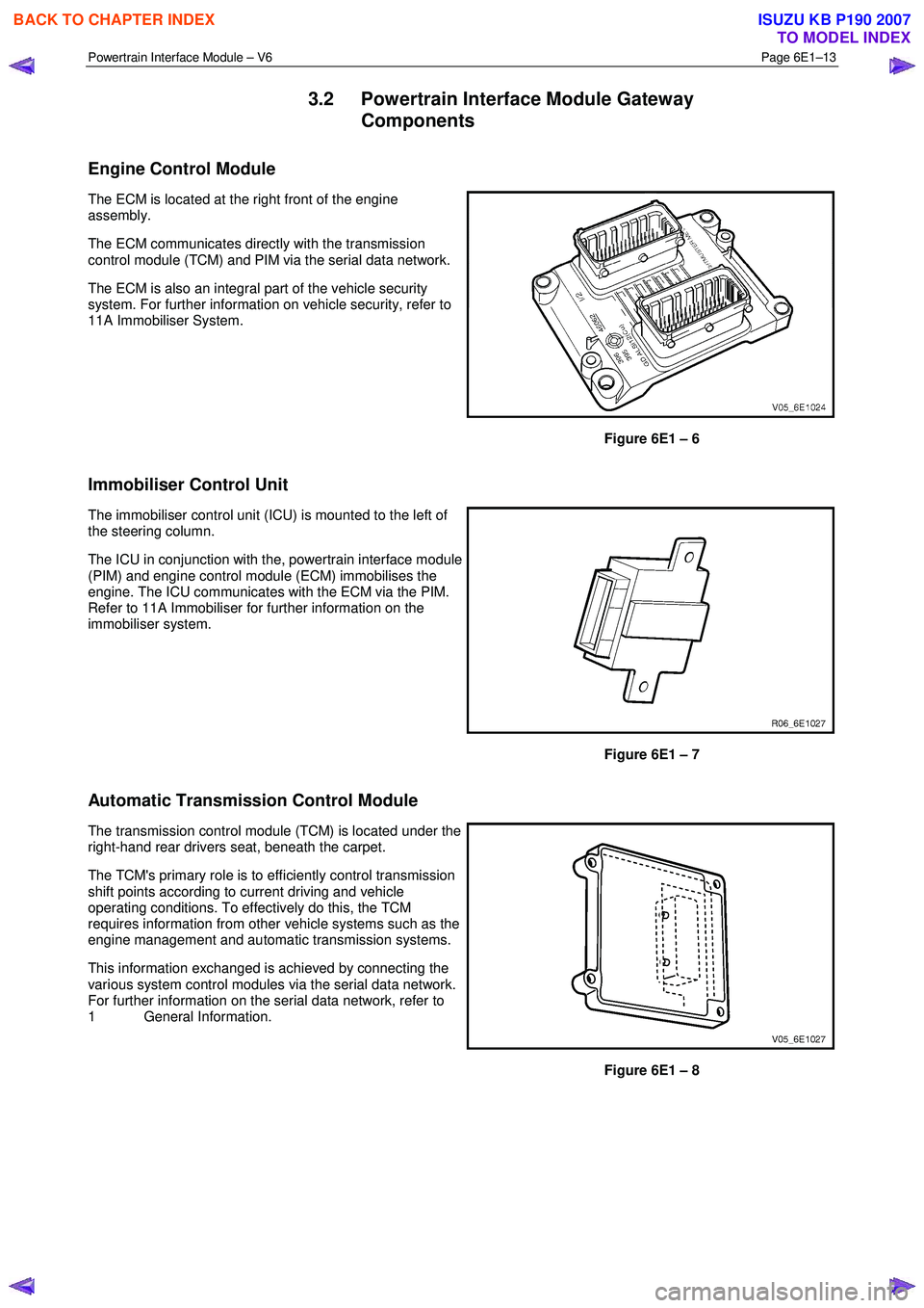
The ECM is located at the right front of the engine
assembly.
The ECM communicates directly with the transmission
control module (TCM) and PIM via the serial data network.
The ECM is also an integral part of the vehicle security
system. For further information on vehicle security, refer to
11A Immobiliser System.
Figure 6E1 – 6
Immobiliser Control Unit
The immobiliser control unit (ICU) is mounted to the left of
the steering column.
The ICU in conjunction with the, powertrain interface module
(PIM) and engine control module (ECM) immobilises the
engine. The ICU communicates with the ECM via the PIM.
Refer to 11A Immobiliser for further information on the
immobiliser system.
Figure 6E1 – 7
Automatic Transmission Control Module
The transmission control module (TCM) is located under the
right-hand rear drivers seat, beneath the carpet.
The TCM's primary role is to efficiently control transmission
shift points according to current driving and vehicle
operating conditions. To effectively do this, the TCM
requires information from other vehicle systems such as the
engine management and automatic transmission systems.
This information exchanged is achieved by connecting the
various system control modules via the serial data network.
For further information on the serial data network, refer to
1 General Information.
Figure 6E1 – 8
BACK TO CHAPTER INDEX
TO MODEL INDEX
ISUZU KB P190 2007
Page 3675 of 6020
Powertrain Interface Module – V6 Page 6E1–14
3.3 Powertrain Interface Module Direct Input
Switches
The following switches are direct wired to the PIM. These switches use the PIM to convert their input signals into serial
data, which is then used by the various vehicle control modules to perform varying functions.
Cruise Control Switch
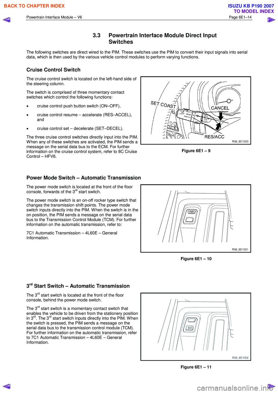
The cruise control switch is located on the left-hand side of
the steering column.
The switch is comprised of three momentary contact
switches which control the following functions:
• cruise control push button switch (ON–OFF),
• cruise control resume – accelerate (RES–ACCEL),
and
• cruise control set – decelerate (SET–DECEL).
The three cruise control switches directly input into the PIM.
W hen any of these switches are activated, the PIM sends a
message on the serial data bus to the ECM. For further
information on the cruise control system, refer to 8C Cruise
Control – HFV6.
Figure 6E1 – 9
Power Mode Switch – Automatic Transmission
The power mode switch is located at the front of the floor
console, forwards of the 3rd start switch.
The power mode switch is an on-off rocker type switch that
changes the transmission shift points. The power mode
switch inputs directly into the PIM. W hen the switch is in the
on position, the PIM sends a message on the serial data
bus to the Transmission Control Module (TCM). For further
information on the automatic transmission, refer to:
7C1 Automatic Transmission – 4L60E – General
Information.
Figure 6E1 – 10
3
rd Start Switch – Automatic Transmission
The 3rd start switch is located at the front of the floor
console, behind the power mode switch.
The 3
rd start switch is a momentary contact switch that
enables the vehicle to be driven from the stationery position
in 3
rd. The 3rd start switch inputs directly into the PIM. W hen
the switch is pressed, the PIM sends a message on the
serial data bus to the transmission control module (TCM).
For further information on the automatic transmission, refer
to 7C1 Automatic Transmission – 4L60E – General
Information.
Figure 6E1 – 11
BACK TO CHAPTER INDEX
TO MODEL INDEX
ISUZU KB P190 2007
Page 3688 of 6020
Powertrain Interface Module – V6 Page 6E1–27
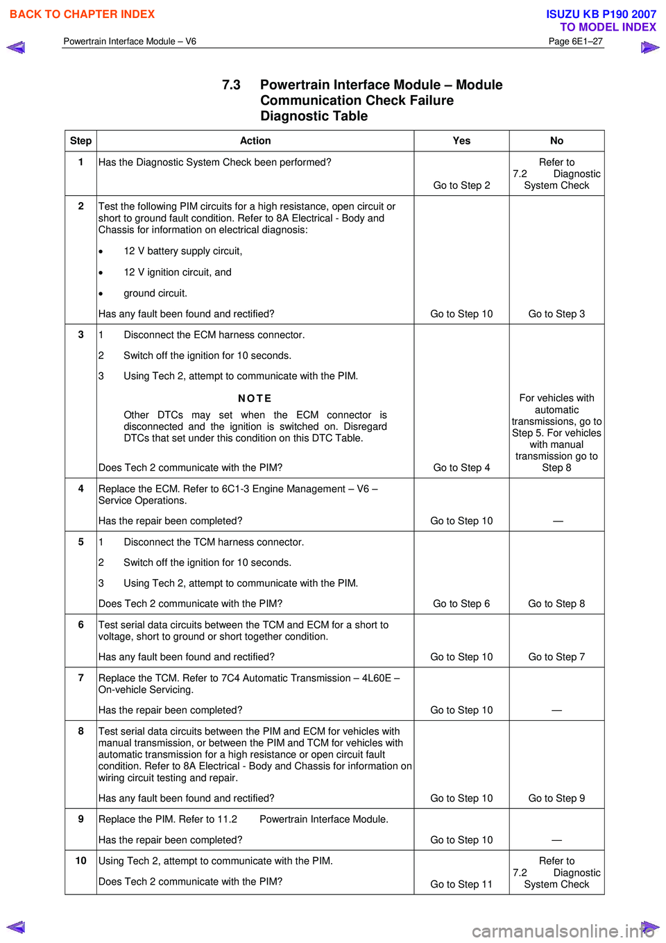
7.3 Powertrain Interface Module – Module
Communication Check Failure
Diagnostic Table
Step Action Yes No
1
Has the Diagnostic System Check been performed?
Go to Step 2 Refer to
7.2 Diagnostic System Check
2 Test the following PIM circuits for a high resistance, open circuit or
short to ground fault condition. Refer to 8A Electrical - Body and
Chassis for information on electrical diagnosis:
• 12 V battery supply circuit,
• 12 V ignition circuit, and
• ground circuit.
Has any fault been found and rectified? Go to Step 10 Go to Step 3
3 1 Disconnect the ECM harness connector.
2 Switch off the ignition for 10 seconds.
3 Using Tech 2, attempt to communicate with the PIM.
NOTE
Other DTCs may set when the ECM connector is
disconnected and the ignition is switched on. Disregard
DTCs that set under this condition on this DTC Table.
Does Tech 2 communicate with the PIM? Go to Step 4 For vehicles with
automatic
transmissions, go to
Step 5. For vehicles with manual
transmission go to Step 8
4 Replace the ECM. Refer to 6C1-3 Engine Management – V6 –
Service Operations.
Has the repair been completed? Go to Step 10 —
5 1 Disconnect the TCM harness connector.
2 Switch off the ignition for 10 seconds.
3 Using Tech 2, attempt to communicate with the PIM.
Does Tech 2 communicate with the PIM? Go to Step 6 Go to Step 8
6 Test serial data circuits between the TCM and ECM for a short to
voltage, short to ground or short together condition.
Has any fault been found and rectified? Go to Step 10 Go to Step 7
7 Replace the TCM. Refer to 7C4 Automatic Transmission – 4L60E –
On-vehicle Servicing.
Has the repair been completed? Go to Step 10 —
8 Test serial data circuits between the PIM and ECM for vehicles with
manual transmission, or between the PIM and TCM for vehicles with
automatic transmission for a high resistance or open circuit fault
condition. Refer to 8A Electrical - Body and Chassis for information on
wiring circuit testing and repair.
Has any fault been found and rectified? Go to Step 10 Go to Step 9
9 Replace the PIM. Refer to 11.2 Powertrain Interface Module.
Has the repair been completed? Go to Step 10 —
10 Using Tech 2, attempt to communicate with the PIM.
Does Tech 2 communicate with the PIM? Go to Step 11 Refer to
7.2 Diagnostic System Check
BACK TO CHAPTER INDEX
TO MODEL INDEX
ISUZU KB P190 2007