2007 ISUZU KB P190 automatic transmission
[x] Cancel search: automatic transmissionPage 3725 of 6020
Powertrain Interface Module – V6 Page 6E1–64
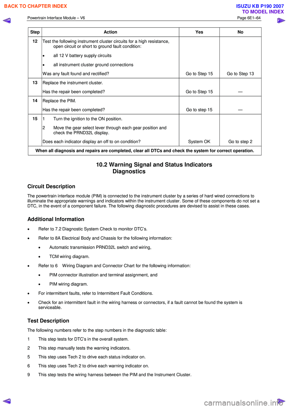
Step Action Yes No
12
Test the following instrument cluster circuits for a high resistance,
open circuit or short to ground fault condition:
• all 12 V battery supply circuits
• all instrument cluster ground connections
W as any fault found and rectified? Go to Step 15 Go to Step 13
13 Replace the instrument cluster.
Has the repair been completed? Go to Step 15 —
14 Replace the PIM.
Has the repair been completed? Go to step 15 —
15 1 Turn the ignition to the ON position.
2 Move the gear select lever through each gear position and check the PRND32L display.
Does each indicator display an off to on condition? System OK Go to step 2
When all diagnosis and repairs are completed, clear all DTCs and check the system for correct operation.
10.2 Warning Signal and Status Indicators Diagnostics
Circuit Description
The powertrain interface module (PIM) is connected to the instrument cluster by a series of hard wired connections to
illuminate the appropriate warnings and indicators within the instrument cluster. Some of these components do not set a
DTC, in the event of a component failure. The following diagnostic procedures are devised to assist in these cases.
Additional Information
• Refer to 7.2 Diagnostic System Check to monitor DTC’s.
• Refer to 8A Electrical Body and Chassis for the following information:
• Automatic transmission PRND32L switch and wiring,
• TCM wiring diagram.
• Refer to 6 W iring Diagram and Connector Chart for the following information:
• PIM connector illustration and terminal assignment, and
• PIM wiring diagram.
• For intermittent faults, refer to Intermittent Fault Conditions.
• Check for an intermittent fault in the wiring harness or connectors, if a fault cannot be found the system is
serviceable.
Test Description
The following numbers refer to the step numbers in the diagnostic table:
1 This step tests for DTC’s in the overall system.
2 This step manually tests the warning indicators.
5 This step uses Tech 2 to drive each status indicator on.
6 This step uses Tech 2 to drive each warning indicator on.
9 This step tests the wiring harness between the PIM and the Instrument Cluster.
BACK TO CHAPTER INDEX
TO MODEL INDEX
ISUZU KB P190 2007
Page 3737 of 6020
Powertrain Interface Module – V6 Page 6E1–76
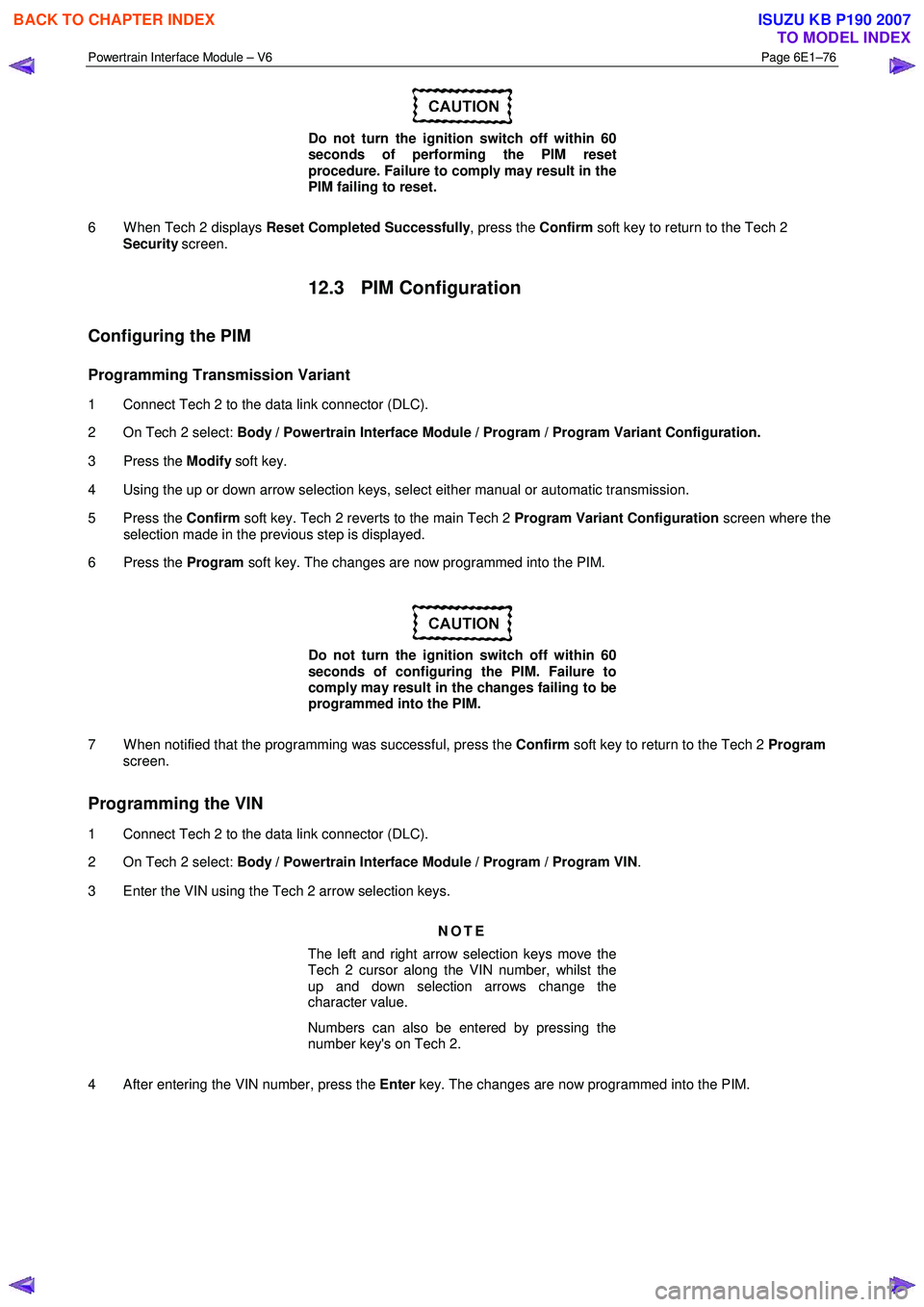
Do not turn the ignition switch off within 60
seconds of performing the PIM reset
procedure. Failure to comply may result in the
PIM failing to reset.
6 W hen Tech 2 displays Reset Completed Successfully , press the Confirm soft key to return to the Tech 2
Security screen.
12.3 PIM Configuration
Configuring the PIM
Programming Transmission Variant
1 Connect Tech 2 to the data link connector (DLC).
2 On Tech 2 select: Body / Powertrain Interface Module / Program / Program Variant Configuration.
3 Press the Modify soft key.
4 Using the up or down arrow selection keys, select either manual or automatic transmission.
5 Press the Confirm soft key. Tech 2 reverts to the main Tech 2 Program Variant Configuration screen where the
selection made in the previous step is displayed.
6 Press the Program soft key. The changes are now programmed into the PIM.
Do not turn the ignition switch off within 60
seconds of configuring the PIM. Failure to
comply may result in the changes failing to be
programmed into the PIM.
7 W hen notified that the programming was successful, press the Confirm soft key to return to the Tech 2 Program
screen.
Programming the VIN
1 Connect Tech 2 to the data link connector (DLC).
2 On Tech 2 select: Body / Powertrain Interface Module / Program / Program VIN .
3 Enter the VIN using the Tech 2 arrow selection keys.
NOTE
The left and right arrow selection keys move the
Tech 2 cursor along the VIN number, whilst the
up and down selection arrows change the
character value.
Numbers can also be entered by pressing the
number key's on Tech 2.
4 After entering the VIN number, press the Enter key. The changes are now programmed into the PIM.
BACK TO CHAPTER INDEX
TO MODEL INDEX
ISUZU KB P190 2007
Page 3743 of 6020
Powertrain Interface Module – V6 Page 6E1–82
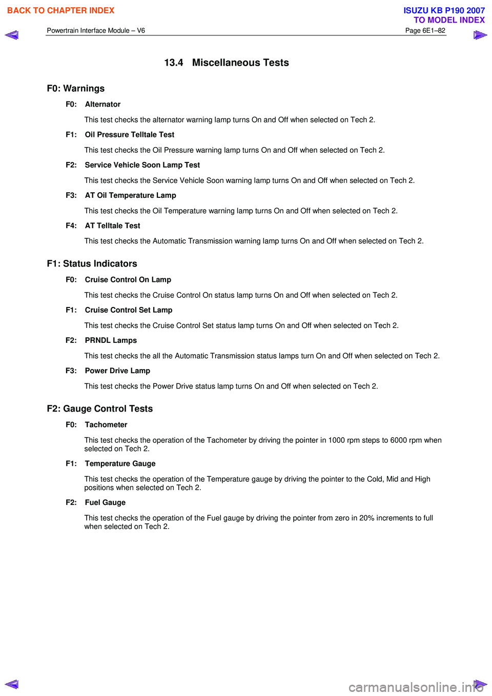
13.4 Miscellaneous Tests
F0: Warnings
F0: Alternator
This test checks the alternator warning lamp turns On and Off when selected on Tech 2.
F1: Oil Pressure Telltale Test
This test checks the Oil Pressure warning lamp turns On and Off when selected on Tech 2.
F2: Service Vehicle Soon Lamp Test
This test checks the Service Vehicle Soon warning lamp turns On and Off when selected on Tech 2.
F3: AT Oil Temperature Lamp
This test checks the Oil Temperature warning lamp turns On and Off when selected on Tech 2.
F4: AT Telltale Test
This test checks the Automatic Transmission warning lamp turns On and Off when selected on Tech 2.
F1: Status Indicators
F0: Cruise Control On Lamp
This test checks the Cruise Control On status lamp turns On and Off when selected on Tech 2.
F1: Cruise Control Set Lamp
This test checks the Cruise Control Set status lamp turns On and Off when selected on Tech 2.
F2: PRNDL Lamps
This test checks the all the Automatic Transmission status lamps turn On and Off when selected on Tech 2.
F3: Power Drive Lamp
This test checks the Power Drive status lamp turns On and Off when selected on Tech 2.
F2: Gauge Control Tests
F0: Tachometer
This test checks the operation of the Tachometer by driving the pointer in 1000 rpm steps to 6000 rpm when
selected on Tech 2.
F1: Temperature Gauge
This test checks the operation of the Temperature gauge by driving the pointer to the Cold, Mid and High
positions when selected on Tech 2.
F2: Fuel Gauge
This test checks the operation of the Fuel gauge by driving the pointer from zero in 20% increments to full when selected on Tech 2.
BACK TO CHAPTER INDEX
TO MODEL INDEX
ISUZU KB P190 2007
Page 3760 of 6020
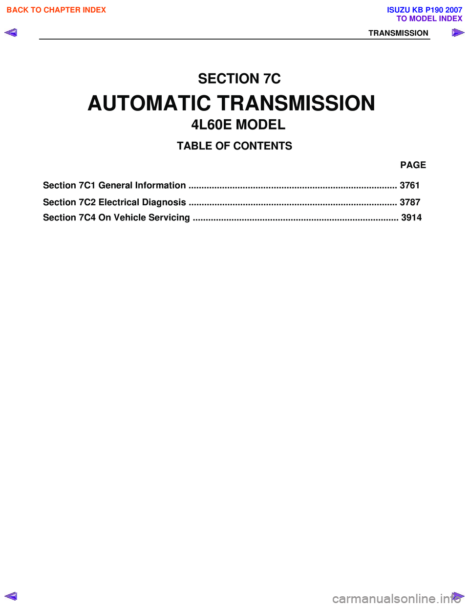
Section 7C1 General Information ................................................................................. 3761 PAGE
Section 7C4 On Vehicle Servicing ................................................................................ 3914
SECTION 7C
AUTOMATIC TRANSMISSION
T A BLE OF CONTENTS
TRANSMISSION
4L60E MODEL
Section 7C2 Electrical Diagnosis ................................................................................. 3787
BACK TO CHAPTER INDEX
TO MODEL INDEX
ISUZU KB P190 2007
Page 3761 of 6020
Automatic Transmission – 4L60E – General Information Page 7C1–1
7C1
Automatic Transmission – 4L60E –
General Information
ATTENTION
Before performing any service operation or other procedure described in this Section, refer to Warnings, Cautions and Notes for correct workshop practices with regard to safety and/or property damage.
1 Section Descriptions ........................................................................................................... ...................3
1.1 WARNINGS, CAUTIONS and NOTES................................................................................................... ................. 3
Definition of WARNING, CAUTION and NOTE Statements ............................................................................. .... 3
WARNING Defined............................................................................................................................................. 3
CAUTION Defined .............................................................................................................................................. 3
NOTE Defined .................................................................................................................................................... 3
1.2 7C1 Automatic Transmission – 4L60E – General Information ....................................................................... .... 4
Recommendations ................................................................................................................................................. 4
Oil Cooler Pipes ..................................................................................................................................................... 4
Clean and Inspect .............................................................................................................. .................................... 5
1.3 7C2 Automatic Transmission – 4L60E – Electrical Diagnosis ...................................................................... ..... 5
1.4 7C3 Automatic Transmission – 4L60E – Hydraulic and Mechanical Diagnosis ............................................... 5
1.5 7C4 Automatic Transmission – 4L60E – On-vehicle Servicing ...................................................................... .... 5
2 General information ...............................................................................................................................6
2.1 Transmission Control Module – HFV6 ............................................................................................. .................... 6
2.2 Transmission Identification .................................................................................................................................. 6
2.3 Economy, Power and Cruise Modes .................................................................................................................... 7
Economy Mode ...................................................................................................................................................... 7
Power Mode ............................................................................................................................................................ 7
Cruise Mode ........................................................................................................................................................... 7
2.4 System Protection Devices ...................................................................................................... ............................. 8
2.5 Self Diagnosis ........................................................................................................................................................ 8
2.6 TCM Sensors and Actuators ................................................................................................................................. 8
3 Transmission Control Module Operation Overview ...........................................................................9
3.1 Transmission Control Module .............................................................................................................................. 9
Component Location ............................................................................................................. ................................ 9
Transmission Control Module Data Transfer ...................................................................................... ................ 9
Transmission Control Module Operation........................................................................................................... 10
3.2 TCM Wiring Diagrams.......................................................................................................................................... 10
4 Transmission Definitions and Abbreviations ....................................................................................1 1
4.1 Throttle Position Related Definitions ................................................................................................................. 11
4.2 Noise Condition Related Definitions ............................................................................................ ...................... 11
4.3 General Definitions .............................................................................................................................................. 11
4.4 Abbreviations ....................................................................................................................................................... 14
5 Service Notes ........................................................................................................................................15
Fasteners .............................................................................................................................................................. 15
General Workshop Practice ................................................................................................................................ 15
6 Torque Specifications .......................................................................................................... ................16
7 Transmission Specifications.................................................................................................... ...........17
BACK TO CHAPTER INDEX
TO MODEL INDEX
ISUZU KB P190 2007
Page 3762 of 6020
Automatic Transmission – 4L60E – General Information Page 7C1–2
7.1 General.................................................................................................................................................................. 17
8 Special Tools ........................................................................................................................................20
BACK TO CHAPTER INDEX
TO MODEL INDEX
ISUZU KB P190 2007
Page 3763 of 6020
Automatic Transmission – 4L60E – General Information Page 7C1–3
1 Section Descriptions
Service information for the Hydra-matic 4L60E Automatic transmission has been divided into five Sections to assist the
technician to quickly locate the correct service, maintenance and diagnostic information.
The following provides a brief outline of each of the Sections.
• 7C1 Automatic Transmission – 4L60E – General Information
• 7C2 Automatic Transmission – 4L60E – Electrical Diagnosis
• 7C3 Automatic Transmission – 4L60E – Hydraulic and Mechanical Diagnosis
• 7C4 Automatic Transmission – 4L60E – On-vehicle Servicing
The following provides a brief outline of each of the Sections.
1.1 WARNINGS, CAUTIONS and NOTES
This Section contains various W ARNINGS, CAUTIONS and NOTE statements that you must observe carefully to reduce
the risk of death or injury during service, repair procedures or vehicle operation. Incorrect service or repair procedures
may damage the vehicle or cause operational faults. W ARNINGS, CAUTION and NOTE statements are not exhaustive.
GM HOLDEN LTD can not possibly warn of all the potentially hazardous consequences of failure to follow these
instructions.
Definition of WARNING, CAUTION and NOTE Statements
Diagnosis and repair procedures in this Section contain both general and specific W ARNING, CAUTION and NOTE
statements. GM HOLDEN LTD is dedicated to the presentation of service information that helps the technician to
diagnose and repair the systems necessary for proper operation of the vehicle. Certain procedures may present a hazard
to the technician if they are not followed in the recommended manner. W ARNING, CAUTION and NOTE statements are
designed to help prevent these hazards from occurring, but not all hazards can be foreseen.
WARNING Defined
A W ARNING statement immediately precedes an operating procedure or maintenance practice which, if not correctly
followed, could result in death or injury. A WARNING statement alerts you to take necessary action or not to take a
prohibited action. If a W ARNING statement is ignored, the following consequences may occur:
• Death or injury to the technician or other personnel working on the vehicle,
• Death or injury to other people in or near the workplace area, and / or
• Death or injury to the driver / or passenger(s) of the vehicle or other people, if the vehicle has been improperly
repaired.
CAUTION Defined
A CAUTION statement immediately precedes an operating procedure or maintenance practice which, if not correctly
followed, could result in damage to or destruction of equipment, or corruption of data. If a CAUTION statement is ignored,
the following consequences may occur:
• Damage to the vehicle,
• Unnecessary vehicle repairs or component replacement,
• Faulty operation or performance of any system or component being repaired,
• Damage to any system or components which depend on the proper operation of the system or component being
repaired,
• Faulty operation or performance of any systems or components which depend on the proper operation or
performance of the system or component under repair,
• Damage to fasteners, basic tools or special tools and / or
• Leakage of coolant, lubricant or other vital fluids.
NOTE Defined
A NOTE statement immediately precedes or follows an operating procedure, maintenance practice or condition that
requires highlighting. A NOTE statement also emphasises necessary characteristics of a diagnostic or repair procedure.
A NOTE statement is designed to:
• Clarify a procedure,
• Present additional information for accomplishing a procedure,
• Give insight into the reasons for performing a procedure in the recommended manner, and / or
• Present information that gives the technician the benefit of past experience in accomplishing a procedure with
greater ease.
BACK TO CHAPTER INDEX
TO MODEL INDEX
ISUZU KB P190 2007
Page 3764 of 6020
Automatic Transmission – 4L60E – General Information Page 7C1–4
1.2 7C1 Automatic Transmission – 4L60E –
General Information
This section provides general information about the automatic transmission, including:
• A glossary of terms,
• Transmission identification information,
• Electrical overview of the Transmission Control Module (TCM),
• Some notes that address safe workshop practices,
• Service notes relating to fasteners and consumable items used at various stages throughout this section,
• Special tools required to work on the transmission,
• Fastener torque specifications, and
• Transmission specifications.
For all information relating to the mechanical construction and function of the 4L60E automatic transmission, refer to the
General Motors Powertrain Group Electronically Controlled Automatic Transmission Technician’s Guide.
This guide includes such information as:
• Transmission Cutaway Views,
• Principles of Operation,
• Power Flow,
• Complete Hydraulic Circuits,
• Bushing and Bearing Locations,
• Seal Locations and
• Illustrated Parts List.
NOTE
Specifications quoted in this General Motors
Powertrain Group Electronically Controlled
Automatic Transmission Technician Guide may
not be for the vehicle you are working on. For
correct specifications refer to
7 Transmission Specifications.
Recommendations
When servicing the transmission, all parts should be cleaned and inspected. Individual units should be reassembled
before disassembly of other units to avoid confusion and interchanging of parts.
a Thoroughly clean the transmission exterior before removal of any component.
b Disassembly and reassembly must be made on a clean work bench. Cleanliness is of the utmost importance, the bench tools and parts must be kept clean at all times.
c Before installing screws and other fasteners into aluminium parts, dip screw threads into transmission fluid to prevent galling aluminium threads and to prevent screws from seizing.
d To prevent thread stripping, always use a torque wrench when installing screws or nuts.
e If threads in aluminium parts are stripped or damaged, the parts can be made serviceable by the use of commercially available thread inserts.
f Protective tools must be used when assembling seals to prevent damage. The slightest flaw in the sealing surface of the seal can cause an oil leak.
g Aluminium castings and valve parts are very susceptible to nicks, burrs, etc. and should be handled with care.
h Expand Internal snap rings and compress external snap rings if they are to be re-used to ensure proper seating when reinstalled.
i Do not re-use removed O-rings, gaskets and oil seals.
j Teflon oil seal rings should not be removed unless damaged.
k During assembly of each unit, all internal moving parts must be lubricated with transmission fluid.
Oil Cooler Pipes
Should any transmission fluid cooling pipe suffer accidental damage, a genuine replacement pipe must be fitted. Refer to
the current release of PartFinder™ to determine the correct part number for the particular engine and pipe involved.
Reworking of damaged pipes or hand made replacements are not permitted.
BACK TO CHAPTER INDEX
TO MODEL INDEX
ISUZU KB P190 2007