2007 ISUZU KB P190 automatic transmission
[x] Cancel search: automatic transmissionPage 3773 of 6020
Automatic Transmission – 4L60E – General Information Page 7C1–13
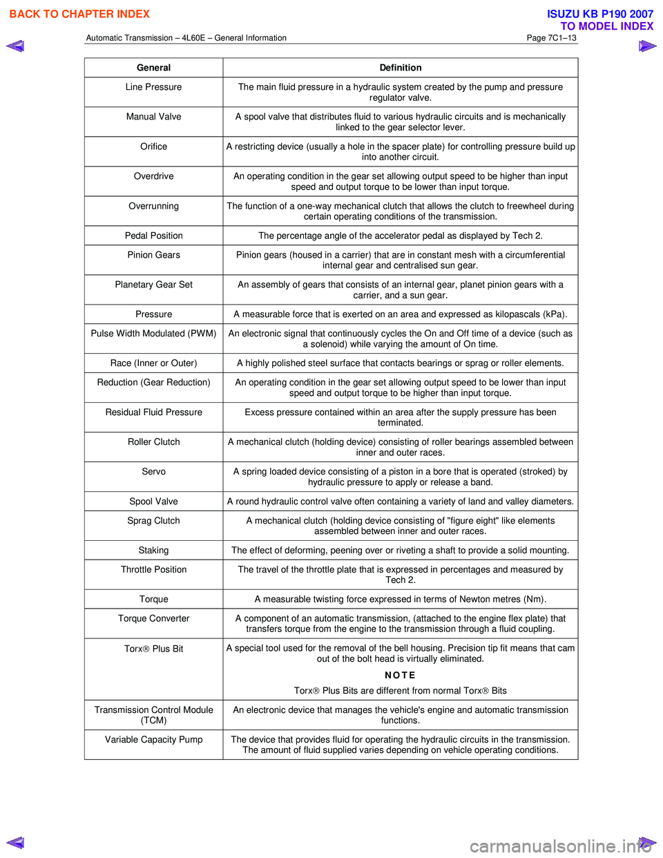
General Definition
Line Pressure The main fluid pressure in a hydraulic system created by the pump and pressure
regulator valve.
Manual Valve A spool valve that distributes fluid to various hydraulic circuits and is mechanically
linked to the gear selector lever.
Orifice A restricting device (usually a hole in the spacer plate) for controlling pressure build up
into another circuit.
Overdrive An operating condition in the gear set allowing output speed to be higher than input
speed and output torque to be lower than input torque.
Overrunning The function of a one-way mechanical clutch that allows the clutch to freewheel during certain operating conditions of the transmission.
Pedal Position The percentage angle of the accelerator pedal as displayed by Tech 2.
Pinion Gears Pinion gears (housed in a carrier) that are in constant mesh with a circumferential
internal gear and centralised sun gear.
Planetary Gear Set An assembly of gears that consists of an internal gear, planet pinion gears with a carrier, and a sun gear.
Pressure A measurable force that is exerted on an area and expressed as kilopascals (kPa).
Pulse Width Modulated (PW M) An electronic signal that continuously cycles the On and Off time of a device (such as
a solenoid) while varying the amount of On time.
Race (Inner or Outer) A highly polished steel surface that contacts bearings or sprag or roller elements.
Reduction (Gear Reduction) An operating condition in the gear set allowing output speed to be lower than input speed and output torque to be higher than input torque.
Residual Fluid Pressure Excess pressure contained within an area after the supply pressure has been terminated.
Roller Clutch A mechanical clutch (holding device) consisting of roller bearings assembled between inner and outer races.
Servo A spring loaded device consisting of a piston in a bore that is operated (stroked) by
hydraulic pressure to apply or release a band.
Spool Valve A round hydraulic control valve often containing a variety of land and valley diameters.
Sprag Clutch A mechanical clutch (holding device consisting of "figure eight" like elements
assembled between inner and outer races.
Staking The effect of deforming, peening over or riveting a shaft to provide a solid mounting.
Throttle Position The travel of the throttle plate that is expressed in percentages and measured by
Tech 2.
Torque A measurable twisting force expressed in terms of Newton metres (Nm).
Torque Converter A component of an automatic transmission, (attached to the engine flex plate) that
transfers torque from the engine to the transmission through a fluid coupling.
Torx Plus Bit A special tool used for the removal of the bell housing. Precision tip fit means that cam
out of the bolt head is virtually eliminated.
NOTE
Torx
Plus Bits are different from normal Torx
Bits
Transmission Control Module
(TCM) An electronic device that manages the vehicle's engine and automatic transmission
functions.
Variable Capacity Pump The device that provides fluid for operating the hydraulic circuits in the transmission. The amount of fluid supplied varies depending on vehicle operating conditions.
BACK TO CHAPTER INDEX
TO MODEL INDEX
ISUZU KB P190 2007
Page 3774 of 6020
Automatic Transmission – 4L60E – General Information Page 7C1–14
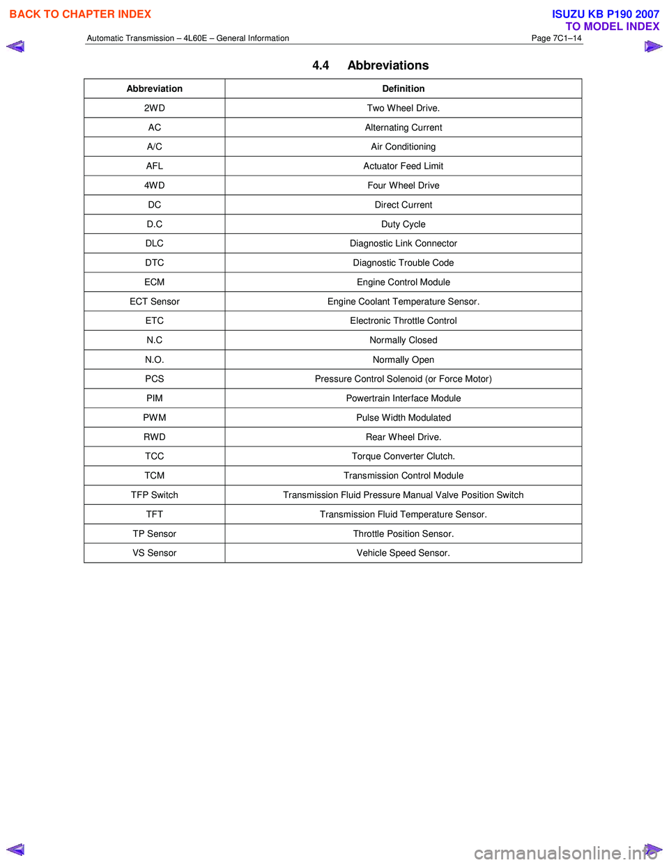
4.4 Abbreviations
Abbreviation Definition
2W D Two W heel Drive.
AC Alternating Current
A/C Air Conditioning
AFL Actuator Feed Limit
4W D Four W heel Drive
DC Direct Current
D.C Duty Cycle
DLC Diagnostic Link Connector
DTC Diagnostic Trouble Code
ECM Engine Control Module
ECT Sensor Engine Coolant Temperature Sensor.
ETC Electronic Throttle Control
N.C Normally Closed
N.O. Normally Open
PCS Pressure Control Solenoid (or Force Motor)
PIM Powertrain Interface Module
PW M Pulse W idth Modulated
RWD Rear Wheel Drive.
TCC Torque Converter Clutch.
TCM Transmission Control Module
TFP Switch Transmission Fluid Pressure Manual Valve Position Switch
TFT Transmission Fluid Temperature Sensor.
TP Sensor Throttle Position Sensor.
VS Sensor Vehicle Speed Sensor.
BACK TO CHAPTER INDEX
TO MODEL INDEX
ISUZU KB P190 2007
Page 3775 of 6020

Automatic Transmission – 4L60E – General Information Page 7C1–15
5 Service Notes
In the interests of safety to personnel, equipment and to the vehicle and its components, read and adhere to the following
notes whenever servicing operations are to be carried out on the Hydra-matic 4L60E automatic transmission. In addition,
some of this information also refers to sound workshop practices and, to achieve the design life of affected components.
Fasteners
• Always reinstall fasteners in the same locations as they were removed.
• If a fastener requires replacement, always use a part of the correct part number or of equal size and strength or
stronger.
General Workshop Practice
• Keep work area and tools clean.
• To avoid unnecessary contamination, always clean the exterior of the transmission before removing any parts.
• Do not use wiping cloths or rags because of the risk of lint being trapped in the transmission.
• Do not use solvents on:
• neoprene seals,
• composition faced clutch plates, or
• thrust washers.
• Always wear eye protection when using compressed air.
• Blow out all passages with compressed air. Only probe small passages with soft, thin wire.
• Handle parts with care to avoid nicks and scratches.
• Do not remove Teflon oil seal rings unless damaged or performing a complete overhaul.
• Expand internal snap rings and compress external snap rings to maximise retention and security.
• Lubricate all internal parts with transmission fluid (only use Dexron® III), as they are being installed.
• When installing cap screws into aluminium castings:
• always use a torque wrench and
• stripped or damaged threads in aluminium castings may be reconditioned by using commercially available
thread inserts.
• Once removed, replace all gaskets, seals and O-rings with new parts.
• Always use seal protectors where indicated and do not use gasket cement or sealant on any joined face unless
specified to do so.
BACK TO CHAPTER INDEX
TO MODEL INDEX
ISUZU KB P190 2007
Page 3776 of 6020
Automatic Transmission – 4L60E – General Information Page 7C1–16
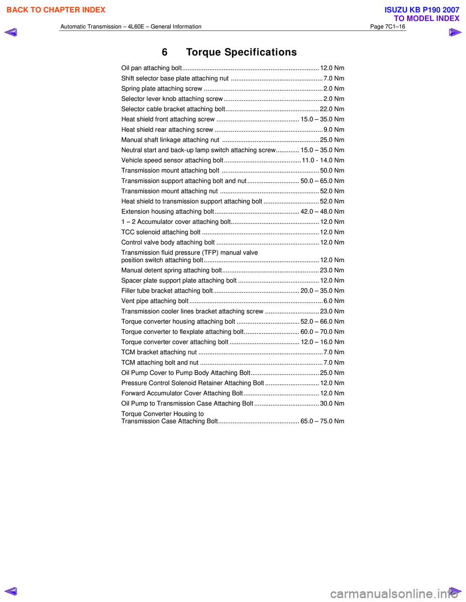
6 Torque Specifications
Oil pan attaching bolt ............................................................................ 12.0 Nm
Shift selector base plate attaching nut ................................................... 7.0 Nm
Spring plate attaching screw .................................................................. 2.0 Nm
Selector lever knob attaching screw ....................................................... 2.0 Nm
Selector cable bracket attaching bolt.................................................... 22.0 Nm
Heat shield front attaching screw .............................................. 15.0 – 35.0 Nm
Heat shield rear attaching screw ............................................................ 9.0 Nm
Manual shaft linkage attaching nut ...................................................... 25.0 Nm
Neutral start and back-up lamp switch attaching screw............. 15.0 – 35.0 Nm
Vehicle speed sensor attaching bolt ........................................... 11.0 - 14.0 Nm
Transmission mount attaching bolt ...................................................... 50.0 Nm
Transmission support attaching bolt and nut ............................. 50.0 – 65.0 Nm
Transmission mount attaching nut ....................................................... 52.0 Nm
Heat shield to transmission support attaching bolt ............................... 52.0 Nm
Extension housing attaching bolt ............................................... 42.0 – 48.0 Nm
1 – 2 Accumulator cover attaching bolt................................................. 12.0 Nm
TCC solenoid attaching bolt ................................................................. 12.0 Nm
Control valve body attaching bolt ......................................................... 12.0 Nm
Transmission fluid pressure (TFP) manual valve
position switch attaching bolt ................................................................ 12.0 Nm
Manual detent spring attaching bolt ...................................................... 23.0 Nm
Spacer plate support plate attaching bolt ............................................. 12.0 Nm
Filler tube bracket attaching bolt................................................ 20.0 – 35.0 Nm
Vent pipe attaching bolt .......................................................................... 6.0 Nm
Transmission cooler lines bracket attaching screw .............................. 23.0 Nm
Torque converter housing attaching bolt ................................... 52.0 – 66.0 Nm
Torque converter to flexplate attaching bolt............................... 60.0 – 70.0 Nm
Torque converter cover attaching bolt ....................................... 12.0 – 16.0 Nm
TCM bracket attaching nut ..................................................................... 7.0 Nm
TCM attaching bolt and nut .................................................................... 7.0 Nm
Oil Pump Cover to Pump Body Attaching Bolt...................................... 25.0 Nm
Pressure Control Solenoid Retainer Attaching Bolt .............................. 12.0 Nm
Forward Accumulator Cover Attaching Bolt .......................................... 12.0 Nm
Oil Pump to Transmission Case Attaching Bolt .................................... 30.0 Nm
Torque Converter Housing to
Transmission Case Attaching Bolt............................................. 65.0 – 75.0 Nm
BACK TO CHAPTER INDEX
TO MODEL INDEX
ISUZU KB P190 2007
Page 3777 of 6020
Automatic Transmission – 4L60E – General Information Page 7C1–17
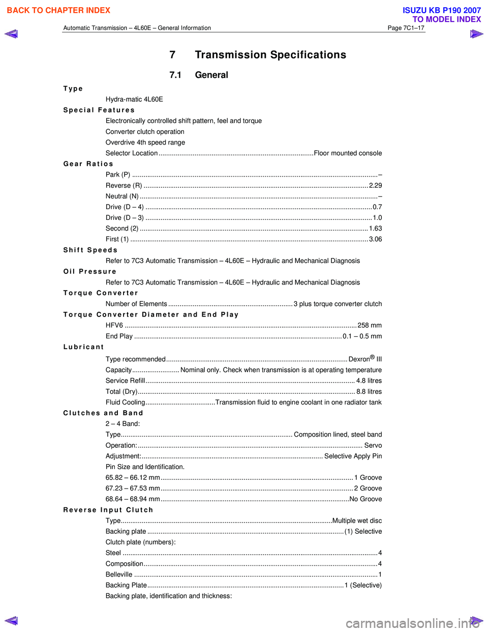
7 Transmission Specifications
7.1 General
Type
Hydra-matic 4L60E
Special Features
Electronically controlled shift pattern, feel and torque
Converter clutch operation
Overdrive 4th speed range
Selector Location ..................................................................................Floor mounted console
Gear Ratios Park (P) ....................................................................................................................... ........... –
Reverse (R) .................................................................................................................... ... 2.29
Neutral (N) .............................................................................................................................. –
Drive (D – 4) .................................................................................................................. ...... 0.7
Drive (D – 3) .................................................................................................................. ...... 1.0
Second (2) ......................................................................................................................... 1.63
First (1) ...................................................................................................................... ........ 3.06
Shift Speeds Refer to 7C3 Automatic Transmission – 4L60E – Hydraulic and Mechanical Diagnosis
Oil Pressure
Refer to 7C3 Automatic Transmission – 4L60E – Hydraulic and Mechanical Diagnosis
Torque Converter
Number of Elements .................................................................. 3 plus torque converter clutch
Torque Converter Diameter and End Play
HFV6 ........................................................................................................................... 258 mm
End Play .............................................................................................................. 0.1 – 0.5 mm
Lubricant
Type recommended ................................................................................................ Dexron
® III
Capacity......................... Nominal only. Check when transmission is at operating temperature
Service Refill ............................................................................................................... 4. 8 litres
Total (Dry)................................................................................................................... 8 .8 litres
Fluid Cooling.....................................Transmission fluid to engine coolant in one radiator tank
Clutches and Band 2 – 4 Band:
Type........................................................................................... Composition lined, steel band
Operation: ..................................................................................................................... .. Servo
Adjustment: ................................................................................................ Selective Apply Pin
Pin Size and Identification.
65.82 – 66.12 mm ...................................................................................................... 1 Groove
67.23 – 67.53 mm ...................................................................................................... 2 Groove
68.64 – 68.94 mm ....................................................................................................No Groove
Reverse Input Clutch Type................................................................................................................Multiple we t disc
Backing plate ........................................................................................................ (1) Select ive
Clutch plate (numbers):
Steel ....................................................................................................................................... 4
Composition............................................................................................................................ 4
Belleville ..................................................................................................................... ............ 1
Backing Plate ........................................................................................................ 1 (Selecti ve)
Backing plate, identification and thickness:
BACK TO CHAPTER INDEX
TO MODEL INDEX
ISUZU KB P190 2007
Page 3778 of 6020
Automatic Transmission – 4L60E – General Information Page 7C1–18
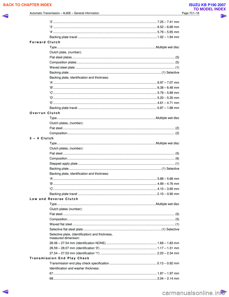
'2' ..................................................................................................................... 7.25 – 7.41 mm
'3' ..................................................................................................................... 6.52 – 6.68 mm
'4' ..................................................................................................................... 5.79 – 5.95 mm
Backing plate travel ......................................................................................... 1.02 – 1.94 mm
Forward Clutch Type................................................................................................................Multiple we t disc
Clutch plate, (number):
Flat steel plates.............................................................................................................. ...... (5)
Composition plates ............................................................................................................. .(5)
Waved steel plate .............................................................................................................. .. (1)
Backing plate ........................................................................................................ (1) Select ive
Backing plate, identification and thickness:
'A' ..................................................................................................................... 6.97 – 7.07 mm
'B' ..................................................................................................................... 6.38 – 6.48 mm
'C'..................................................................................................................... 5.79 – 5.89 mm
'D'..................................................................................................................... 5.20 – 5.30 mm
'E' ..................................................................................................................... 4.61 – 4.71 mm
Backing plate travel ......................................................................................... 0.87 – 1.88 mm
Overrun Clutch Type................................................................................................................Multiple we t disc
Clutch plates, (number):
Flat steel ..................................................................................................................... ......... (2)
Composition.................................................................................................................... ..... (2)
3 – 4 Clutch Type................................................................................................................Multiple we t disc
Clutch plates, (number):
Flat steel ..................................................................................................................... ......... (5)
Composition.................................................................................................................... ..... (6)
Stepped apply plate ............................................................................................................ .(1)
Backing plate ........................................................................................................ (1) Select ive
Backing plate, identification and thickness:
'A' ..................................................................................................................... 5.88 – 5.68 mm
'B' ..................................................................................................................... 4.99 – 4.76 mm
'C'..................................................................................................................... 4.10 – 3.90 mm
Backing plate travel ......................................................................................... 2.10 – 0.90 mm
Low and Reverse Clutch Type................................................................................................................Multiple we t disc
Clutch plates (number):
Flat steel ..................................................................................................................... ......... (5)
Composition.................................................................................................................... ..... (5)
Waved flat steel ............................................................................................................... .... (1)
Selective flat steel plate ........................................................................................ (1) Selective
Selective plate, (identification) and thickness,
measured dimension:
28.06 – 27.54 mm (identification NONE) ......................................................... 1.68 – 1.83 mm
28.59 – 28.07 mm (identification '0') ................................................................ 1.17 – 1.31 mm
27.54 – 27.03 mm (identification '1') ................................................................ 2.20 – 2.34 mm
Transmission End Play Check
Transmission end play check specification ...................................................... 0.13 – 0.92 mm
Identification and washer thickness:
67..................................................................................................................... 1.87 – 1 .97 mm
68..................................................................................................................... 2.04 – 2 .14 mm
BACK TO CHAPTER INDEX
TO MODEL INDEX
ISUZU KB P190 2007
Page 3779 of 6020
Automatic Transmission – 4L60E – General Information Page 7C1–19
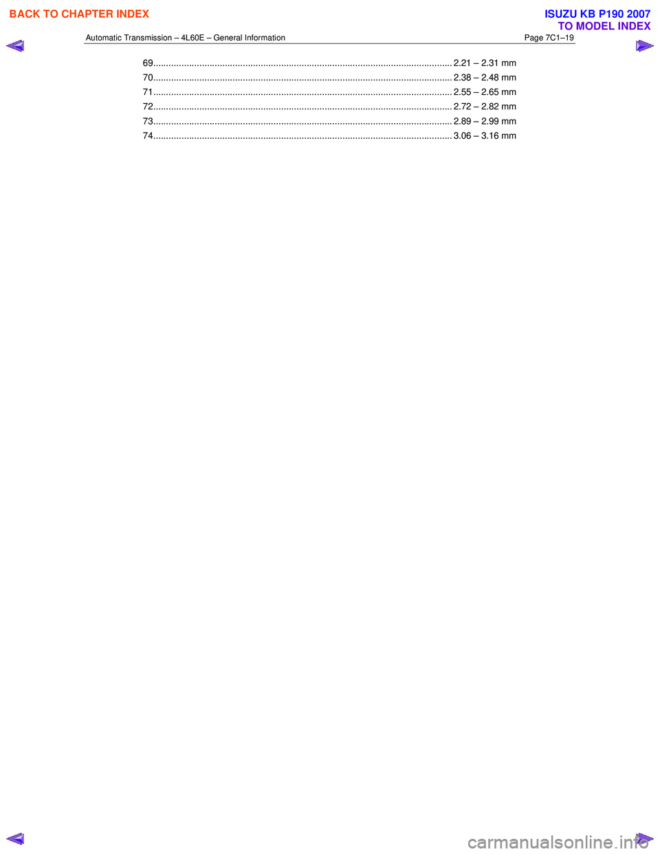
69..................................................................................................................... 2.21 – 2.31 mm
70..................................................................................................................... 2.38 – 2 .48 mm
71..................................................................................................................... 2.55 – 2 .65 mm
72..................................................................................................................... 2.72 – 2 .82 mm
73..................................................................................................................... 2.89 – 2 .99 mm
74..................................................................................................................... 3.06 – 3 .16 mm
BACK TO CHAPTER INDEX
TO MODEL INDEX
ISUZU KB P190 2007
Page 3780 of 6020

Automatic Transmission – 4L60E – General Information Page 7C1–20
8 Special Tools
The following pages list and illustrate the special service tools required. The tools are classified into the following
categories:
Mandatory:
W hen required to perform routine maintenance operations and adjustments, or are required to carry out
fault diagnosis procedures.
Desirable:
These tools should be considered for purchase since their use will greatly facilitate performing designated
tasks and permit achievement of standard times.
Unique: These tools are those that must be employed when overhauling major assemblies or performing relatively
large tasks.
Available: Are those tools that are of a general nature for which commercially available equivalents exist, or tools
which have had previous application.
Unless otherwise specified, all tools are available from:
SPX Australia PTY. LTD. Service Solutions 28 Clayton Road
Notting Hill, Victoria, 3168
Telephone: (03) 9544 6222
Facsimile: (03) 9544 5222
Tool Number Illustration Description Tool Classification
700-4208
Pass-Thru Connector Remover
Used to release the four locking tangs
on the Pass-Thru connector from the
transmission case.
Previously released Desirable
J6125-1B
Slide Hammer
Used for a number of bush removal
operations.
Previously released Unique
J8092
Driver Handle
Used for a number of bush installation
operations.
Previously released Unique
J8433 Puller
Used with J21427-01 to remove the
output speed sensor ring from the
main shaft.
Previously released Unique
J8763-02 Holding Fixture
Used in conjunction with holding
fixture base J3289-20 to hold
automatic transmission.
Previously released. Unique
BACK TO CHAPTER INDEX
TO MODEL INDEX
ISUZU KB P190 2007