2007 ISUZU KB P190 automatic transmission
[x] Cancel search: automatic transmissionPage 3441 of 6020
Engine Management – V6 – Diagnostics Page 6C1-2–163
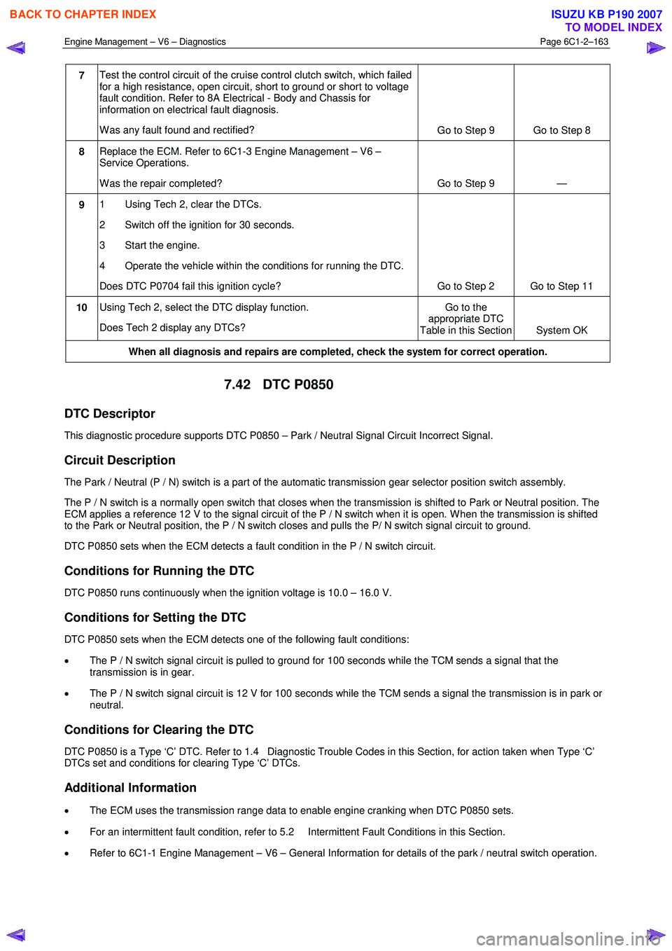
7 Test the control circuit of the cruise control clutch switch, which failed
for a high resistance, open circuit, short to ground or short to voltage
fault condition. Refer to 8A Electrical - Body and Chassis for
information on electrical fault diagnosis.
W as any fault found and rectified? Go to Step 9 Go to Step 8
8 Replace the ECM. Refer to 6C1-3 Engine Management – V6 –
Service Operations.
W as the repair completed? Go to Step 9 —
9 1 Using Tech 2, clear the DTCs.
2 Switch off the ignition for 30 seconds.
3 Start the engine.
4 Operate the vehicle within the conditions for running the DTC.
Does DTC P0704 fail this ignition cycle? Go to Step 2 Go to Step 11
10 Using Tech 2, select the DTC display function.
Does Tech 2 display any DTCs? Go to the
appropriate DTC
Table in this Section System OK
When all diagnosis and repairs are completed, check the system for correct operation.
7.42 DTC P0850
DTC Descriptor
This diagnostic procedure supports DTC P0850 – Park / Neutral Signal Circuit Incorrect Signal.
Circuit Description
The Park / Neutral (P / N) switch is a part of the automatic transmission gear selector position switch assembly.
The P / N switch is a normally open switch that closes when the transmission is shifted to Park or Neutral position. The
ECM applies a reference 12 V to the signal circuit of the P / N switch when it is open. W hen the transmission is shifted
to the Park or Neutral position, the P / N switch closes and pulls the P/ N switch signal circuit to ground.
DTC P0850 sets when the ECM detects a fault condition in the P / N switch circuit.
Conditions for Running the DTC
DTC P0850 runs continuously when the ignition voltage is 10.0 – 16.0 V.
Conditions for Setting the DTC
DTC P0850 sets when the ECM detects one of the following fault conditions:
• The P / N switch signal circuit is pulled to ground for 100 seconds while the TCM sends a signal that the
transmission is in gear.
• The P / N switch signal circuit is 12 V for 100 seconds while the TCM sends a signal the transmission is in park or
neutral.
Conditions for Clearing the DTC
DTC P0850 is a Type ‘C’ DTC. Refer to 1.4 Diagnostic Trouble Codes in this Section, for action taken when Type ‘C’
DTCs set and conditions for clearing Type ‘C’ DTCs.
Additional Information
• The ECM uses the transmission range data to enable engine cranking when DTC P0850 sets.
• For an intermittent fault condition, refer to 5.2 Intermittent Fault Conditions in this Section.
• Refer to 6C1-1 Engine Management – V6 – General Information for details of the park / neutral switch operation.
BACK TO CHAPTER INDEX
TO MODEL INDEX
ISUZU KB P190 2007
Page 3442 of 6020
Engine Management – V6 – Diagnostics Page 6C1-2–164
• Since fault condition in a wiring connector may trigger DTCs, always test the connectors related to this diagnostic
procedure for shorted terminals or poor wiring connection before replacing any component. Refer to 8A Electrical -
Body and Chassis for information on electrical fault diagnosis.
• To assist diagnosis, refer to 3 W iring Diagrams and Connector Charts in this Section, for the system wiring
diagram and connector charts.
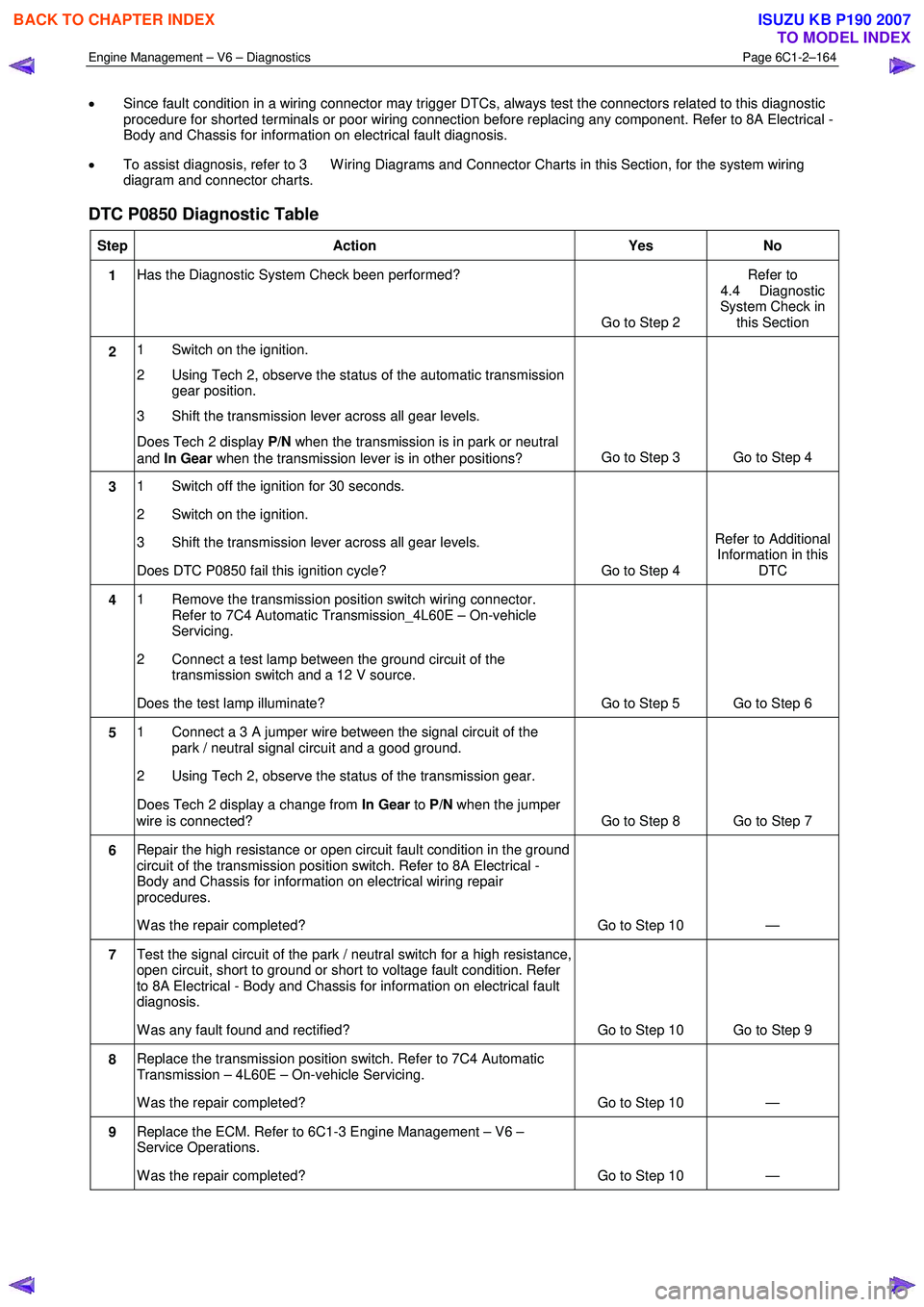
DTC P0850 Diagnostic Table
Step Action Yes No
1 Has the Diagnostic System Check been performed?
Go to Step 2 Refer to
4.4 Diagnostic
System Check in this Section
2 1 Switch on the ignition.
2 Using Tech 2, observe the status of the automatic transmission gear position.
3 Shift the transmission lever across all gear levels.
Does Tech 2 display P/N when the transmission is in park or neutral
and In Gear when the transmission lever is in other positions? Go to Step 3 Go to Step 4
3
1 Switch off the ignition for 30 seconds.
2 Switch on the ignition.
3 Shift the transmission lever across all gear levels.
Does DTC P0850 fail this ignition cycle? Go to Step 4 Refer to Additional
Information in this DTC
4 1 Remove the transmission position switch wiring connector.
Refer to 7C4 Automatic Transmission_4L60E – On-vehicle
Servicing.
2 Connect a test lamp between the ground circuit of the transmission switch and a 12 V source.
Does the test lamp illuminate? Go to Step 5 Go to Step 6
5 1 Connect a 3 A jumper wire between the signal circuit of the
park / neutral signal circuit and a good ground.
2 Using Tech 2, observe the status of the transmission gear.
Does Tech 2 display a change from In Gear to P/N when the jumper
wire is connected? Go to Step 8 Go to Step 7
6 Repair the high resistance or open circuit fault condition in the ground
circuit of the transmission position switch. Refer to 8A Electrical -
Body and Chassis for information on electrical wiring repair
procedures.
W as the repair completed? Go to Step 10 —
7 Test the signal circuit of the park / neutral switch for a high resistance,
open circuit, short to ground or short to voltage fault condition. Refer
to 8A Electrical - Body and Chassis for information on electrical fault
diagnosis.
W as any fault found and rectified? Go to Step 10 Go to Step 9
8 Replace the transmission position switch. Refer to 7C4 Automatic
Transmission – 4L60E – On-vehicle Servicing.
W as the repair completed? Go to Step 10 —
9 Replace the ECM. Refer to 6C1-3 Engine Management – V6 –
Service Operations.
W as the repair completed? Go to Step 10 —
BACK TO CHAPTER INDEX
TO MODEL INDEX
ISUZU KB P190 2007
Page 3499 of 6020
Engine Management – V6 – Diagnostics Page 6C1-2–221
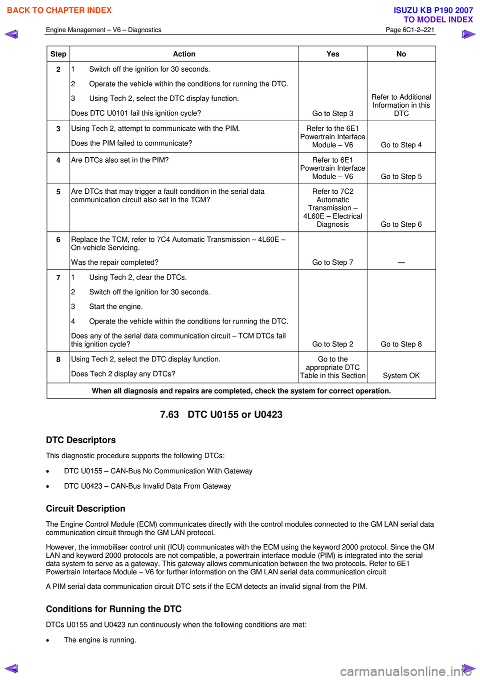
Step Action Yes No
2 1 Switch off the ignition for 30 seconds.
2 Operate the vehicle within the conditions for running the DTC.
3 Using Tech 2, select the DTC display function.
Does DTC U0101 fail this ignition cycle? Go to Step 3 Refer to Additional
Information in this DTC
3 Using Tech 2, attempt to communicate with the PIM.
Does the PIM failed to communicate? Refer to the 6E1
Powertrain Interface Module – V6 Go to Step 4
4 Are DTCs also set in the PIM? Refer to 6E1
Powertrain Interface Module – V6 Go to Step 5
5 Are DTCs that may trigger a fault condition in the serial data
communication circuit also set in the TCM? Refer to 7C2
Automatic
Transmission –
4L60E – Electrical Diagnosis Go to Step 6
6 Replace the TCM, refer to 7C4 Automatic Transmission – 4L60E –
On-vehicle Servicing.
W as the repair completed? Go to Step 7 —
7 1 Using Tech 2, clear the DTCs.
2 Switch off the ignition for 30 seconds.
3 Start the engine.
4 Operate the vehicle within the conditions for running the DTC.
Does any of the serial data communication circuit – TCM DTCs fail
this ignition cycle? Go to Step 2 Go to Step 8
8 Using Tech 2, select the DTC display function.
Does Tech 2 display any DTCs? Go to the
appropriate DTC
Table in this Section System OK
When all diagnosis and repairs are completed, check the system for correct operation.
7.63 DTC U0155 or U0423
DTC Descriptors
This diagnostic procedure supports the following DTCs:
• DTC U0155 – CAN-Bus No Communication W ith Gateway
• DTC U0423 – CAN-Bus Invalid Data From Gateway
Circuit Description
The Engine Control Module (ECM) communicates directly with the control modules connected to the GM LAN serial data
communication circuit through the GM LAN protocol.
However, the immobiliser control unit (ICU) communicates with the ECM using the keyword 2000 protocol. Since the GM
LAN and keyword 2000 protocols are not compatible, a powertrain interface module (PIM) is integrated into the serial
data system to serve as a gateway. This gateway allows communication between the two protocols. Refer to 6E1
Powertrain Interface Module – V6 for further information on the GM LAN serial data communication circuit
A PIM serial data communication circuit DTC sets if the ECM detects an invalid signal from the PIM.
Conditions for Running the DTC
DTCs U0155 and U0423 run continuously when the following conditions are met:
• The engine is running.
BACK TO CHAPTER INDEX
TO MODEL INDEX
ISUZU KB P190 2007
Page 3502 of 6020
Engine Management – V6 – Diagnostics Page 6C1-2–224
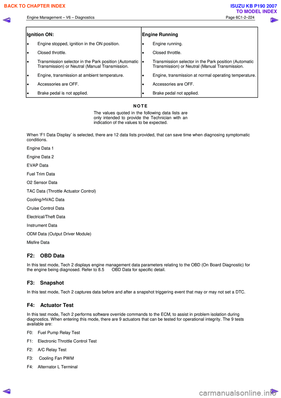
Ignition ON:
• Engine stopped, ignition in the ON position.
• Closed throttle.
• Transmission selector in the Park position (Automatic
Transmission) or Neutral (Manual Transmission.
• Engine, transmission at ambient temperature.
• Accessories are OFF.
• Brake pedal is not applied.
Engine Running
• Engine running.
• Closed throttle.
• Transmission selector in the Park position (Automatic
Transmission) or Neutral (Manual Transmission.
• Engine, transmission at normal operating temperature.
• Accessories are OFF.
• Brake pedal not applied.
NOTE
The values quoted in the following data lists are
only intended to provide the Technician with an
indication of the values to be expected.
W hen ‘F1 Data Display’ is selected, there are 12 data lists provided, that can save time when diagnosing symptomatic
conditions.
Engine Data 1
Engine Data 2
EVAP Data
Fuel Trim Data
O2 Sensor Data
TAC Data (Throttle Actuator Control)
Cooling/HVAC Data
Cruise Control Data
Electrical/Theft Data
Instrument Data
ODM Data (Output Driver Module)
Misfire Data
F2: OBD Data
In this test mode, Tech 2 displays engine management data parameters relating to the OBD (On Board Diagnostic) for
the engine being diagnosed. Refer to 8.5 OBD Data for specific detail.
F3: Snapshot
In this test mode, Tech 2 captures data before and after a snapshot triggering event that may or may not set a DTC.
F4: Actuator Test
In this test mode, Tech 2 performs software override commands to the ECM, to assist in problem isolation during
diagnostics. W hen entering this mode, there are 9 actuators that can be tested for operational integrity. The 9 tests
available are:
F0: Fuel Pump Relay Test
F1: Electronic Throttle Control Test
F2: A/C Relay Test
F3: Cooling Fan PW M
F4: Alternator L Terminal
BACK TO CHAPTER INDEX
TO MODEL INDEX
ISUZU KB P190 2007
Page 3505 of 6020
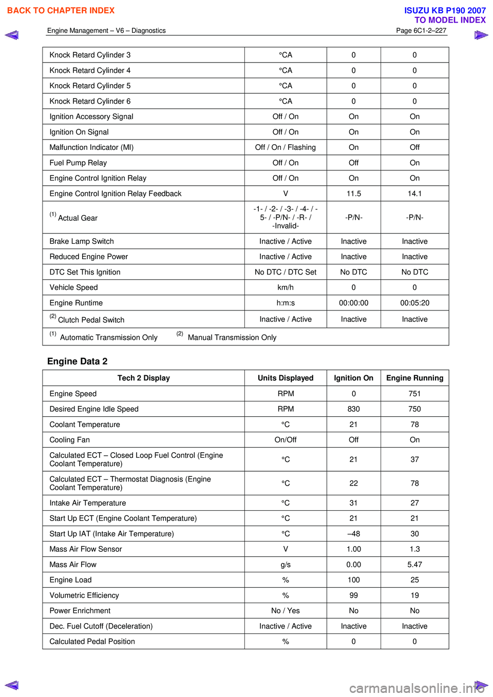
Engine Management – V6 – Diagnostics Page 6C1-2–227
Knock Retard Cylinder 3 °CA 0 0
Knock Retard Cylinder 4 °CA 0 0
Knock Retard Cylinder 5 °CA 0 0
Knock Retard Cylinder 6 °CA 0 0
Ignition Accessory Signal Off / On On On
Ignition On Signal Off / On On On
Malfunction Indicator (MI) Off / On / Flashing On Off
Fuel Pump Relay Off / On Off On
Engine Control Ignition Relay Off / On On On
Engine Control Ignition Relay Feedback V 11.5 14.1
(1) Actual Gear -1- / -2- / -3- / -4- / -
5- / -P/N- / -R- / -Invalid- -P/N- -P/N-
Brake Lamp Switch
Inactive / Active Inactive Inactive
Reduced Engine Power Inactive / Active Inactive Inactive
DTC Set This Ignition No DTC / DTC Set No DTC No DTC
Vehicle Speed km/h 0 0
Engine Runtime h:m:s 00:00:00 00:05:20
(2) Clutch Pedal Switch Inactive / Active Inactive Inactive
(1) Automatic Transmission Only (2) Manual Transmission Only
Engine Data 2
Tech 2 Display
Units Displayed Ignition On Engine Running
Engine Speed RPM 0 751
Desired Engine Idle Speed RPM 830 750
Coolant Temperature °C 21 78
Cooling Fan On/Off Off On
Calculated ECT – Closed Loop Fuel Control (Engine
Coolant Temperature) °C 21 37
Calculated ECT – Thermostat Diagnosis (Engine
Coolant Temperature) °C 22 78
Intake Air Temperature
°C 31 27
Start Up ECT (Engine Coolant Temperature) °C 21 21
Start Up IAT (Intake Air Temperature) °C –48 30
Mass Air Flow Sensor V 1.00 1.3
Mass Air Flow g/s 0.00 5.47
Engine Load % 100 25
Volumetric Efficiency % 99 19
Power Enrichment No / Yes No No
Dec. Fuel Cutoff (Deceleration) Inactive / Active Inactive Inactive
Calculated Pedal Position % 0 0
BACK TO CHAPTER INDEX
TO MODEL INDEX
ISUZU KB P190 2007
Page 3506 of 6020
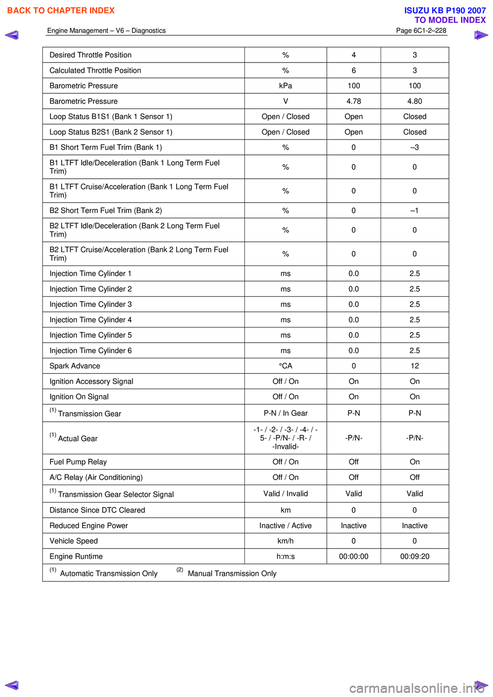
Engine Management – V6 – Diagnostics Page 6C1-2–228
Desired Throttle Position % 4 3
Calculated Throttle Position % 6 3
Barometric Pressure kPa 100 100
Barometric Pressure V 4.78 4.80
Loop Status B1S1 (Bank 1 Sensor 1) Open / Closed Open Closed
Loop Status B2S1 (Bank 2 Sensor 1) Open / Closed Open Closed
B1 Short Term Fuel Trim (Bank 1) % 0 –3
B1 LTFT Idle/Deceleration (Bank 1 Long Term Fuel
Trim) % 0 0
B1 LTFT Cruise/Acceleration (Bank 1 Long Term Fuel
Trim) % 0 0
B2 Short Term Fuel Trim (Bank 2)
% 0 –1
B2 LTFT Idle/Deceleration (Bank 2 Long Term Fuel
Trim) % 0 0
B2 LTFT Cruise/Acceleration (Bank 2 Long Term Fuel
Trim) % 0 0
Injection Time Cylinder 1
ms 0.0 2.5
Injection Time Cylinder 2 ms 0.0 2.5
Injection Time Cylinder 3 ms 0.0 2.5
Injection Time Cylinder 4 ms 0.0 2.5
Injection Time Cylinder 5 ms 0.0 2.5
Injection Time Cylinder 6 ms 0.0 2.5
Spark Advance °CA 0 12
Ignition Accessory Signal Off / On On On
Ignition On Signal Off / On On On
(1) Transmission Gear P-N / In Gear P-N P-N
(1) Actual Gear -1- / -2- / -3- / -4- / -
5- / -P/N- / -R- / -Invalid- -P/N- -P/N-
Fuel Pump Relay
Off / On Off On
A/C Relay (Air Conditioning) Off / On Off Off
(1) Transmission Gear Selector Signal Valid / Invalid Valid
Valid
Distance Since DTC Cleared km 0 0
Reduced Engine Power Inactive / Active Inactive Inactive
Vehicle Speed km/h 0 0
Engine Runtime h:m:s 00:00:00 00:09:20
(1) Automatic Transmission Only (2) Manual Transmission Only
BACK TO CHAPTER INDEX
TO MODEL INDEX
ISUZU KB P190 2007
Page 3508 of 6020
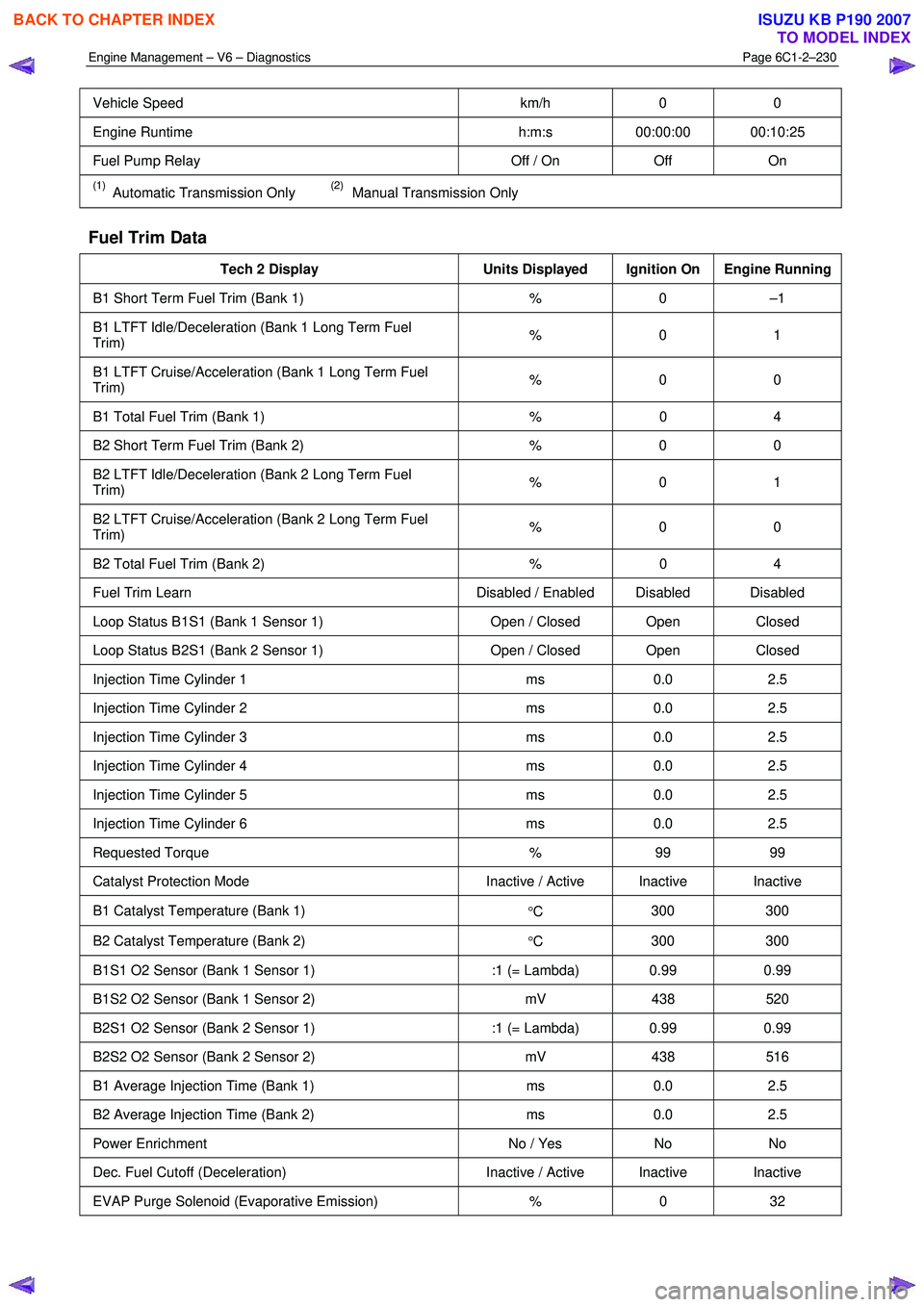
Engine Management – V6 – Diagnostics Page 6C1-2–230
Vehicle Speed km/h 0 0
Engine Runtime h:m:s 00:00:00 00:10:25
Fuel Pump Relay Off / On Off On
(1) Automatic Transmission Only (2) Manual Transmission Only
Fuel Trim Data
Tech 2 Display Units Displayed Ignition On Engine Running
B1 Short Term Fuel Trim (Bank 1) % 0 –1
B1 LTFT Idle/Deceleration (Bank 1 Long Term Fuel
Trim) % 0 1
B1 LTFT Cruise/Acceleration (Bank 1 Long Term Fuel
Trim) % 0 0
B1 Total Fuel Trim (Bank 1)
% 0 4
B2 Short Term Fuel Trim (Bank 2) % 0 0
B2 LTFT Idle/Deceleration (Bank 2 Long Term Fuel
Trim) % 0 1
B2 LTFT Cruise/Acceleration (Bank 2 Long Term Fuel
Trim) % 0 0
B2 Total Fuel Trim (Bank 2)
% 0 4
Fuel Trim Learn Disabled / Enabled Disabled Disabled
Loop Status B1S1 (Bank 1 Sensor 1) Open / Closed Open Closed
Loop Status B2S1 (Bank 2 Sensor 1) Open / Closed Open Closed
Injection Time Cylinder 1 ms 0.0 2.5
Injection Time Cylinder 2 ms 0.0 2.5
Injection Time Cylinder 3 ms 0.0 2.5
Injection Time Cylinder 4 ms 0.0 2.5
Injection Time Cylinder 5 ms 0.0 2.5
Injection Time Cylinder 6 ms 0.0 2.5
Requested Torque % 99 99
Catalyst Protection Mode Inactive / Active Inactive Inactive
B1 Catalyst Temperature (Bank 1)
°C 300 300
B2 Catalyst Temperature (Bank 2)
°C 300 300
B1S1 O2 Sensor (Bank 1 Sensor 1)
:1 (= Lambda) 0.99 0.99
B1S2 O2 Sensor (Bank 1 Sensor 2) mV 438 520
B2S1 O2 Sensor (Bank 2 Sensor 1) :1 (= Lambda) 0.99 0.99
B2S2 O2 Sensor (Bank 2 Sensor 2) mV 438 516
B1 Average Injection Time (Bank 1) ms 0.0 2.5
B2 Average Injection Time (Bank 2) ms 0.0 2.5
Power Enrichment No / Yes No No
Dec. Fuel Cutoff (Deceleration) Inactive / Active Inactive Inactive
EVAP Purge Solenoid (Evaporative Emission) % 0 32
BACK TO CHAPTER INDEX
TO MODEL INDEX
ISUZU KB P190 2007
Page 3509 of 6020

Engine Management – V6 – Diagnostics Page 6C1-2–231
Engine Speed RPM 0 592
Coolant Temperature
°C 39 91
Intake Air Temperature
°C 32 26
Start Up ECT (Engine Coolant Temperature)
°C 39 34
Start Up IAT (Intake Air Temperature)
°C –48 30
Mass Air Flow Sensor
V 1.0 1.2
Engine Load % 100 22
Volumetric Efficiency % 99 15
Calculated Pedal Position % 0 0
Calculated Throttle Position % 5 1
Barometric Pressure kPa 102 102
Barometric Pressure V 4.88 4.88
Spark Advance
°CA 0 12
Ignition On Signal
Off / On On On
(1) Actual Gear -1- / -2- / -3- / -4- / -
5- / -P/N- / -R- / -Invalid- -P/N- -P/N-
DTC Set This Ignition
No DTC / DTC Set No DTC No DTC
Vehicle Speed km/h 0 0
Engine Runtime h:m:s 00:00:00 00:12:30
Ignition Accessory Signal Off / On On On
Mass Air Flow g/s 0.00 3.33
(1) Automatic Transmission Only (2) Manual Transmission Only
O2 Sensor Data
Tech 2 Display Units Displayed Ignition On Engine Running
Loop Status B1S1 (Bank 1 Sensor 1) Open / Closed Open Closed
Loop Status B2S1 (Bank 2 Sensor 1) Open / Closed Open Closed
Commanded B1S1 O2 Sensor Value (Bank 1 Sensor 1) :1 (= Lambda) 0.99 0.94
Commanded B2S1 O2 Sensor Value (Bank 2 Sensor 1) :1 (= Lambda) 0.99 0.94
B1S1 O2 Sensor (Bank 1 Sensor 1) :1 (= Lambda) 0.99 0.94
B1S2 O2 Sensor (Bank 1 Sensor 2) mV 438 538
B2S1 O2 Sensor (Bank 2 Sensor 1) :1 (= Lambda) 0.99 0.99
B2S2 O2 Sensor (Bank 2 Sensor 2) mV 438 486
B1S1 O2 Sensor Heater (Bank 1 Sensor 1) Ohm 540 80
B2S1 O2 Sensor Heater (Bank 2 Sensor 1) Ohm 540 80
Commanded B1S1 O2 Sensor Heater (Bank 1 Sensor 1) % 0.0 42.0
Commanded B2S1 O2 Sensor Heater (Bank 2 Sensor 1) % 0.0 42.0
B1 Short Term Fuel Trim (Bank 1) % 0 –1
B1 LTFT Idle/Deceleration (Bank 1 Long Term Fuel
Trim) % 0 1
BACK TO CHAPTER INDEX
TO MODEL INDEX
ISUZU KB P190 2007