Page 2670 of 6020
Engine Mechanical – V6 Page 6A1–191
Figure 6A1 – 332
Figure 6A1 – 333 Figure 6A1 – 334
42 Fit the engine lifting brackets (1), (EN–46114) and attach the engine hoist, raise the engine to take the weight off the engine mounts.
Engine Lift Bracket Attaching Bolt
torque specification
.............................................................58.0 – 72.0.0 Nm
43 Remove the left-hand side knock sensor (1).
Figure 6A1 – 335
NOTE
Removal or the starter motor is only required for
vehicles with an Automatic Transmission.
BACK TO CHAPTER INDEX
TO MODEL INDEX
ISUZU KB P190 2007
Page 2671 of 6020
Engine Mechanical – V6 Page 6A1–192
44 Remove the left-hand side engine mount (1), (automatic transmission only).
Figure 6A1 – 336
45 Unclip the oil level sensor harness from the heat shield (1).
a Remove the heat shield retaining screw (2).
b Remove the lower starter motor attaching bolt (3).
c Remove the heat shield.
d Remove the upper starter motor retaining bolt (3).
46 Remove the starter motor from the engine block and lower the starter motor as far as possible to gain
access to the wiring harness connections.
47 Remove the starter motor, (automatic transmission only).
Figure 6A1 – 337
48 Reinstall the left-hand side engine mount (1), (automatic transmission only).
49 Remove the transmission assembly, refer to 7C1 Automatic – 4L60E – General Information.
BACK TO CHAPTER INDEX
TO MODEL INDEX
ISUZU KB P190 2007
Page 2677 of 6020

Engine Mechanical – V6 Page 6A1–198
k Timing chains, tensioners, shoes, guides & sprockets, refer to 3.16 Timing Chains, Tensioners, Shoes and
Guides.
l Cylinder head assemblies, refer to 3.22 Cylinder Head Assembly.
m Oil pan assembly, refer to 4.2 Oil Pan and Oil Pump Suction Pipe Assembly.
n Piston and connecting rod assemblies, refer to 4.5 Pistons, Pins, Rings, Connecting Rods and Big-end Bearings.
o Crankshaft assembly, refer to 4.6 Crankshaft and Main Bearings.
p Piston oil nozzles, refer 4.5 Pistons, Pins, Rings, Connecting Rods and Big-end Bearings.
Reassemble
Reassembly of the engine assembly is the reverse of the disassembly procedure.
Reinstall
Reinstallation of the engine assembly is the reverse to the removal procedure, noting the following:
NOTE
Refer to 6 Torque Wrench Specifications
for the correct torque specifications.
1 Tighten the fasteners to the correct torque specification.
Engine ground connector bolt
torque specification ............................................10.0 Nm
Power steering high pressure line
attaching bolt torque specification .............8.0 – 12.0 Nm
Power steering high pressure line
flare nut torque specification ...................25.0 – 35.0 Nm
Engine mount to frame attaching bolt
torque specification .................................44.0 – 60.0 Nm
Knock Sensor Attaching Nut
torque specification ............................................23.0 Nm
2 Use only the specified engine lubricant type and quantity. It is recommended that a fluorescent oil dye, such as that contained in J 28481-B, be added to assist in any future oil leak diagnosis.
3 Fill the cooling system with the correct quantity and grade of coolant, refer to 6B1 Engine Cooling – V6.
4 Check transmission fluid level, replenishing as required, using the specified lubricant for the transmission fitted, refer to 7C1 Automatic – 4L60E – General Information.
5 Disable the ignition system, refer to 6C1-3 Engine Management – V6 – Service Operations.
6 Crank the engine several times. Listen for any unusual noises or evidence that parts are binding.
7 Enable the ignition system. Start the engine and listen for any unusual noises.
8 Check the vehicle oil pressure gauge or warning indicator and confirm the engine has acceptable oil pressure. If required, install an oil pressure gauge and measure the engine oil pressure, refer to 2.19 Engine Oil Pressure
Diagnosis.
9 Run the engine at about 1,000 r.p.m. until the engine has reached normal operating temperature.
10 Listen for any unusual noises.
11 Check for oil, fuel, coolant and exhaust leaks while the engine is running, correcting as required.
12 Perform a final inspection for correct engine oil and coolant levels.
4.2 Oil Pan and Oil Pump Suction Pipe Assembly
Remove
1 Remove the engine assembly from the vehicle, refer to 4.1 Engine .
2 Separate the engine and transmission assemblies, refer to 7C1 Automatic – 4L60E – General Information.
3 Mount the engine assembly on a suitable engine stand.
4 Remove the engine front cover, refer to 3.15 Front Cover Assembly.
BACK TO CHAPTER INDEX
TO MODEL INDEX
ISUZU KB P190 2007
Page 2682 of 6020
Engine Mechanical – V6 Page 6A1–203
5 Loosely install the oil pan bolts.
6 Tighten the oil pan attaching bolts to the correct torque specification and in the sequence shown.
Oil pan to cylinder block attaching
bolt (1 – 11) torque specification .............20.0 – 26.0 Nm
Oil pan to crankshaft rear oil
seal housing attaching bolt (12 – 13)
torque specification ...................................8.0 – 12.0 Nm
Figure 6A1 – 361
4.3 Flexplate Assembly
Remove
1 Remove the transmission, refer to 7C4 Automatic Transmission – 4L60E – On-vehicle Servicing.
2 Remove the starter motor, refer to 6D1-2 Starting System – V6.
3 Install the flexplate holding tool, Tool No. EN-46106 (1) into the starter motor mounting location.
Figure 6A1 – 362
BACK TO CHAPTER INDEX
TO MODEL INDEX
ISUZU KB P190 2007
Page 2684 of 6020

Engine Mechanical – V6 Page 6A1–205
Reinstall
NOTE
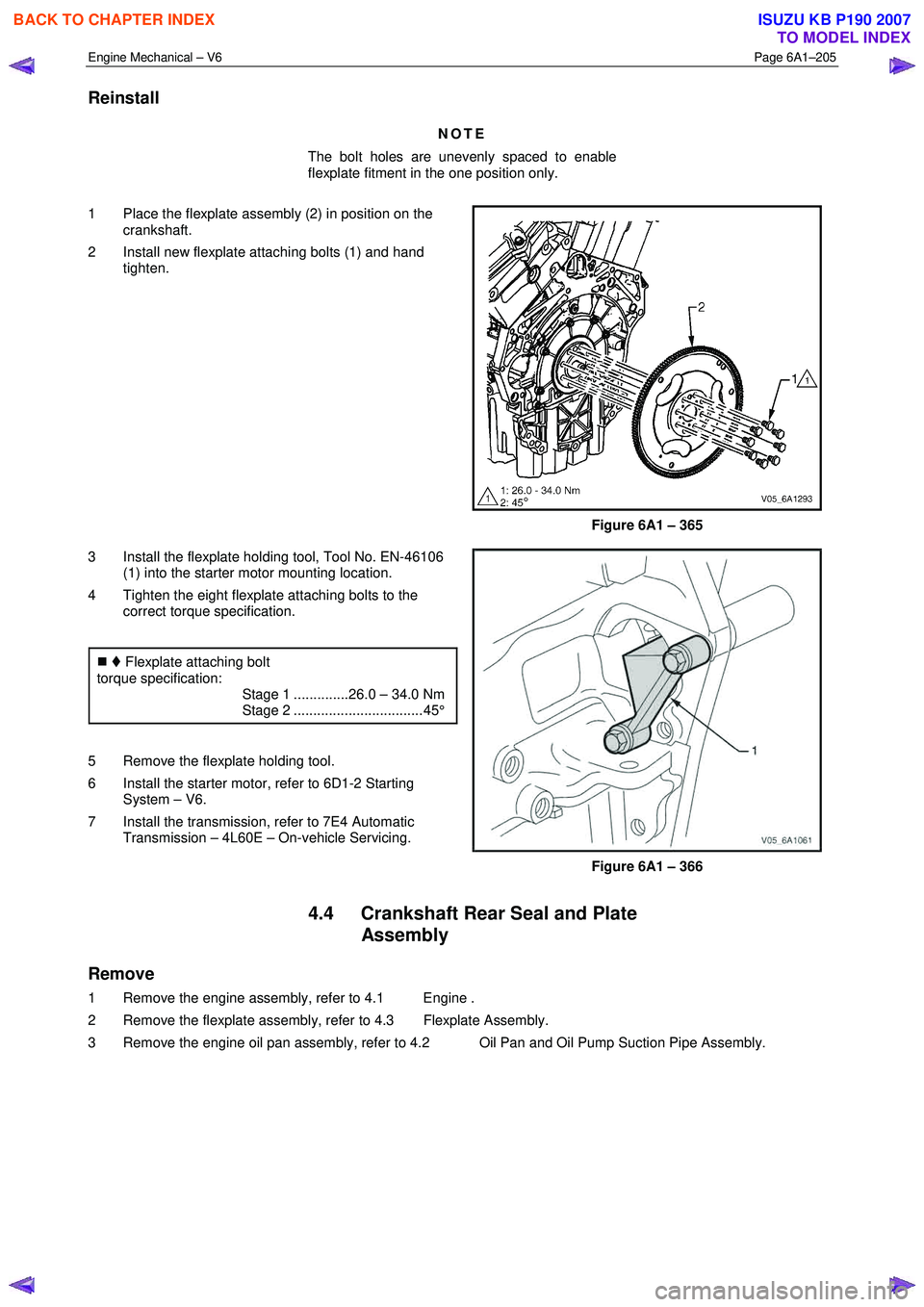
The bolt holes are unevenly spaced to enable
flexplate fitment in the one position only.
1 Place the flexplate assembly (2) in position on the crankshaft.
2 Install new flexplate attaching bolts (1) and hand tighten.
Figure 6A1 – 365
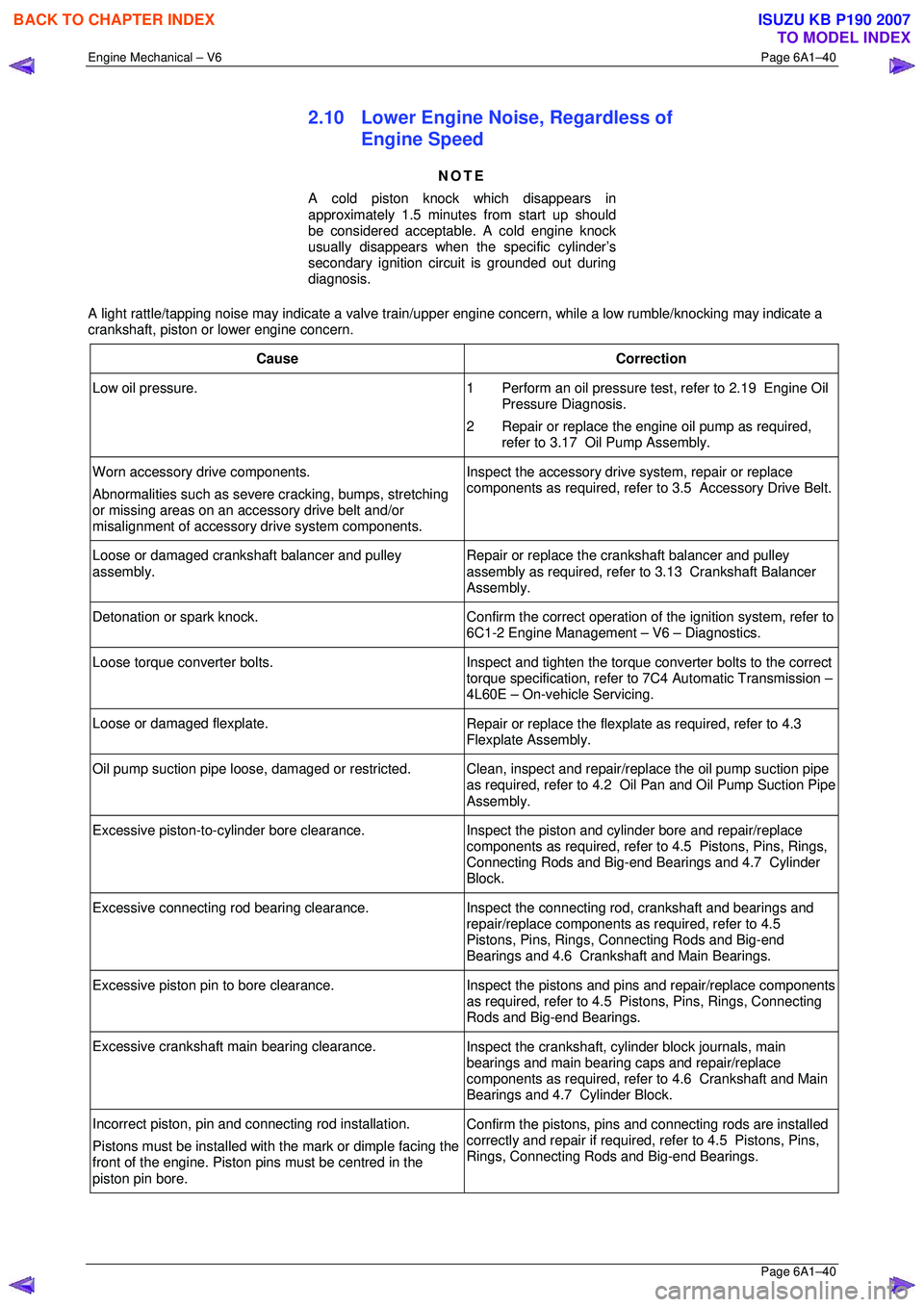
3 Install the flexplate holding tool, Tool No. EN-46106 (1) into the starter motor mounting location.
4 Tighten the eight flexplate attaching bolts to the correct torque specification.
�„ Flexplate attaching bolt
torque specification:
Stage 1 ..............26.0 – 34.0 Nm
Stage 2 ................................. 45°
5 Remove the flexplate holding tool.
6 Install the starter motor, refer to 6D1-2 Starting System – V6.
7 Install the transmission, refer to 7E4 Automatic Transmission – 4L60E – On-vehicle Servicing.
Figure 6A1 – 366
4.4 Crankshaft Rear Seal and Plate Assembly
Remove
1 Remove the engine assembly, refer to 4.1 Engine .
2 Remove the flexplate assembly, refer to 4.3 Flexplate Assembly.
3 Remove the engine oil pan assembly, refer to 4.2 Oil Pan and Oil Pump Suction Pipe Assembly.
BACK TO CHAPTER INDEX
TO MODEL INDEX
ISUZU KB P190 2007
Page 2817 of 6020

Engine Mechanical – V6 Page 6A1–40
Page 6A1–40
2.10 Lower Engine Noise, Regardless of
Engine Speed
NOTE
A cold piston knock which disappears in
approximately 1.5 minutes from start up should
be considered acceptable. A cold engine knock
usually disappears when t he specific cylinder’s
secondary ignition circuit is grounded out during
diagnosis.
A light rattle/tapping noise may indicate a valve train/upper engine concern, while a low rumble/knocking may indicate a
crankshaft, piston or lower engine concern.
Cause Correction
Low oil pressure. 1 Perform an oil pressure test, refer to 2.19 Engine Oil
Pressure Diagnosis.
2 Repair or replace the engine oil pump as required, refer to 3.17 Oil Pump Assembly.
Worn accessory drive components.
Abnormalities such as severe cracking, bumps, stretching
or missing areas on an accessory drive belt and/or
misalignment of accessory drive system components. Inspect the accessory drive system, repair or replace
components as required, refer to 3.5 Accessory Drive Belt.
Loose or damaged crankshaft balancer and pulley
assembly. Repair or replace the crankshaft balancer and pulley
assembly as required, refer to 3.13 Crankshaft Balancer
Assembly.
Detonation or spark knock. Confirm the correct operation of the ignition system, refer to
6C1-2 Engine Management – V6 – Diagnostics.
Loose torque converter bolts. Inspect and tighten the torque converter bolts to the correct
torque specification, refer to 7C4 Automatic Transmission –
4L60E – On-vehicle Servicing.
Loose or damaged flexplate. Repair or replace the flexplate as required, refer to 4.3
Flexplate Assembly.
Oil pump suction pipe loos e, damaged or restricted.
Clean, inspect and repair/replace the oil pump suction pipe
as required, refer to 4.2 O il Pan and Oil Pump Suction Pipe
Assembly.
Excessive piston-to-cylinder bore clearance. Inspect the piston and cylinder bore and repair/replace
components as required, refer to 4.5 Pistons, Pins, Rings,
Connecting Rods and Big-end Bearings and 4.7 Cylinder
Block.
Excessive connecting rod bearing clearance. Inspect the connecting rod, crankshaft and bearings and
repair/replace components as required, refer to 4.5
Pistons, Pins, Rings, Connecting Rods and Big-end
Bearings and 4.6 Crankshaft and Main Bearings.
Excessive piston pin to bore clearance. Inspect the pistons and pins and repair/replace components
as required, refer to 4.5 Pistons, Pins, Rings, Connecting
Rods and Big-end Bearings.
Excessive crankshaft main bearing clearance. Inspect the crankshaft, cylinder block journals, main
bearings and main bearing caps and repair/replace
components as required, refer to 4.6 Crankshaft and Main
Bearings and 4.7 Cylinder Block.
Incorrect piston, pin and c onnecting rod installation.
Pistons must be installed with the mark or dimple facing the
front of the engine. Piston pi ns must be centred in the
piston pin bore. Confirm the pistons, pins and
connecting rods are installed
correctly and repair if required, refer to 4.5 Pistons, Pins,
Rings, Connecting Rods and Big-end Bearings.
BACK TO CHAPTER INDEX
TO MODEL INDEX
ISUZU KB P190 2007
Page 3022 of 6020
Engine Mechanical – V6 Page 6A1–245
Page 6A1–245
35 Disconnect the harness connector from the transmission, refer to Section 7B1 Manual Transmission – V6 or
Section 7C1, Section 7C2, Section 7C3 or Section 7C4 for automatic transmission.
36 Remove the left-hand side exhaust manifold upper heat shield (1), (Automatic transmission only).
Figure 6A1 – 420
37 Progressively loosen the seven exhaust manifold attaching bolts (2), working from the outside to the
centre and then remove the bolts.
38 Manoeuvre the exhaust manifold (3), away from the cylinder head.
39 Remove and discard the exhaust manifold to cylinder head gasket.
Figure 6A1 – 421
40 Remove the engine oil level indicator assembly (1), (automatic transmission only).
41 Remove the left-hand side exhaust manifold, (automatic transmission only).
Figure 6A1 – 422
BACK TO CHAPTER INDEX
TO MODEL INDEX
ISUZU KB P190 2007
Page 3023 of 6020
Engine Mechanical – V6 Page 6A1–246
Page 6A1–246
Figure 6A1 – 423
Figure 6A1 – 424
42 Fit the engine lifting brackets (1), (EN–46114) and attach the engine hoist, raise the engine to take the weight off the engine mounts.
Engine Lift Bracket Attaching Bolt
torque specification
............................................................. 58.0 – 72.0.0 Nm
43 Remove the left-hand side knock sensor (1).
Figure 6A1 – 425
NOTE
Removal or the starter motor is only required for
vehicles with an Automatic Transmission.
BACK TO CHAPTER INDEX
TO MODEL INDEX
ISUZU KB P190 2007