2007 ISUZU KB P190 jump start
[x] Cancel search: jump startPage 3641 of 6020
Battery Page 6D1-3–1
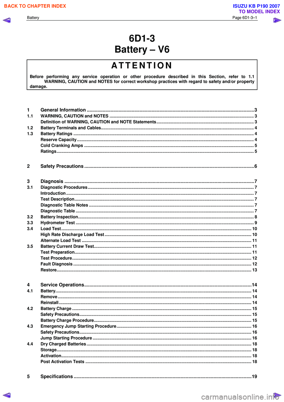
6D1-3
Battery – V6
ATTENTION
Before performing any service operation or other procedure described in this Section, refer to 1.1
WARNING, CAUTION and NOTES for correct workshop practices with regard to safety and/or property
damage.
1 General Information ............................................................................................................ ...................3
1.1 WARNING, CAUTION and NOTES ..................................................................................................... ................... 3
Definition of WARNING, CAUTION and NOTE Statements ............................................................................. .... 3
1.2 Battery Terminals and Cables............................................................................................................................... 4
1.3 Battery Ratings ...................................................................................................................................................... 4
Reserve Capacity ............................................................................................................... .................................... 4
Cold Cranking Amps ............................................................................................................................................. 5
Ratings.................................................................................................................................................................... 5
2 Safety Precautions .................................................................................................................................6
3 Diagnosis ................................................................................................................................................7
3.1 Diagnostic Procedures .......................................................................................................................................... 7
Introduction ............................................................................................................................................................ 7
Test Description ..................................................................................................................................................... 7
Diagnostic Table Notes ......................................................................................................................................... 7
Diagnostic Table .................................................................................................................................................... 7
3.2 Battery Inspection.................................................................................................................................................. 8
3.3 Hydrometer Test .................................................................................................................................................... 9
3.4 Load Test ...................................................................................................................... ........................................ 10
High Rate Discharge Load Test .................................................................................................. ........................ 10
Alternate Load Test ............................................................................................................................................. 11
3.5 Battery Current Draw Test...................................................................................................... ............................. 11
Test Preparation................................................................................................................................................... 11
Test Procedure ..................................................................................................................................................... 12
Fault Diagnosis .................................................................................................................................................... 12
Restore.................................................................................................................................................................. 13
4 Service Operations ...............................................................................................................................14
4.1 Battery................................................................................................................................................................... 14
Remove ......................................................................................................................... ........................................ 14
Reinstall ................................................................................................................................................................ 14
4.2 Battery Charge ................................................................................................................. .................................... 15
Safety Precautions............................................................................................................. .................................. 15
Battery Charge Procedure....................................................................................................... ............................ 15
4.3 Emergency Jump Starting Procedure .............................................................................................. .................. 16
Safety Precautions............................................................................................................................................... 16
Jump Starting Procedure ........................................................................................................ ............................ 16
4.4 Dry Charged Batteries ......................................................................................................................................... 18
Storage.................................................................................................................................................................. 18
Activation..................................................................................................................... ......................................... 18
Post Activation Tests .......................................................................................................... ................................ 18
5 Specifications .......................................................................................................................................19
BACK TO CHAPTER INDEX
TO MODEL INDEX
ISUZU KB P190 2007
Page 3656 of 6020
Battery Page 6D1-3–16
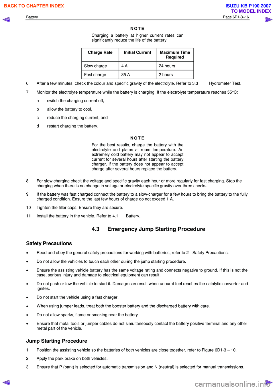
NOTE
Charging a battery at higher current rates can
significantly reduce the life of the battery.
Charge Rate Initial Current Maximum Time Required
Slow charge 4 A 24 hours
Fast charge 35 A 2 hours
6 After a few minutes, check the colour and specific gravity of the electrolyte. Refer to 3.3 Hydrometer Test.
7 Monitor the electrolyte temperature while the battery is charging. If the electrolyte temperature reaches 55 °C:
a switch the charging current off,
b allow the battery to cool,
c reduce the charging current, and
d restart charging the battery.
NOTE
For the best results, charge the battery with the
electrolyte and plates at room temperature. An
extremely cold battery may not appear to accept
current for several hours after starting the battery
charger. If the battery does not appear to accept
charge after several hours replace the battery.
8 For slow charging check the voltage and specific gravity each hour or more regularly for fast charging. Stop the charging when there is no change in voltage or electrolyte specific gravity over three checks.
9 If the battery was fast charged connect the battery to a slow-charger for a few hours to bring the battery to the fully charged condition. Ensure the last few hours of charge do not exceed 1 A.
10 Tighten the filler caps. Ensure they are secure.
11 Install the battery in the vehicle. Refer to 4.1 Battery.
4.3 Emergency Jump Starting Procedure
Safety Precautions
• Read and obey the general safety precautions for working with batteries, refer to 2 Safety Precautions.
• Do not allow the vehicles to touch each other during the jump starting procedure.
• Ensure the assisting vehicle battery has the same voltage rating and connects negative to ground. If this is not the
case, serious injury and damage to electrical equipment can result.
• Do not push or tow the vehicle to start it. Damage can result when unburnt fuel reaches the catalytic converter and
ignites.
• Do not start the vehicle using a fast charger.
• W hen using jumper leads, treat both the booster battery and the discharged battery with care.
• Do not allow sparks, flame or smoking near the battery.
• Ensure that metal tools or jumper cables do not simultaneously contact the battery positive terminal and any other
metal part of the vehicle.
Jump Starting Procedure
1 Position the assisting vehicle so the batteries of both vehicles are close together, refer to Figure 6D1-3 – 10.
2 Apply the park brake on both vehicles.
3 Ensure that P (park) is selected for automatic transmission and N (neutral) is selected for manual transmissions.
BACK TO CHAPTER INDEX
TO MODEL INDEX
ISUZU KB P190 2007
Page 3657 of 6020

Battery Page 6D1-3–17
4 Turn off the ignition, lights and all other electrical loads.
5 Check the battery filler caps on both batteries are tight.
6 Place a wet cloth over the battery filler caps of each battery.
7 Attach one end of the red jumper cable to the positive terminal of the booster battery.
8 Attach the other end of the same cable to the positive terminal of the discharged battery.
9 Attach one end of the black jumper cable to the negative terminal of the booster battery.
10 Attach the other end to a solid stationary, metallic point on the engine of the disabled vehicle.
NOTE
Do not connect this end directly to the negative
post of the discharged battery.
Figure 6D1-3 – 10
Legend
Order of hook-up:
1 Booster vehicle, positive terminal
2 Disabled vehicle, positive terminal
3 Booster vehicle, negative terminal
4 Disabled vehicle, engine ground point Booster vehicle
Disabled vehicle
11 Ensure the jumper cables are not on or near drive pulleys, cooling fans or other points that will move when the engine is started.
12 Start the engine in the booster vehicle and run the engine at a moderate speed for a few minutes.
13 Start the engine in the disabled vehicle.
NOTE
If the engine in the disabled vehicle does not start
within 30 seconds, stop cranking the engine and
fix the cause. Refer to 3 Diagnosis.
14 W hen the engine starts, allow both engines to idle for approximately seven minutes. This allows the voltage levels in both vehicles to balance.
15 Leave the vehicles running and remove the jumper cables in the reverse sequence to attaching them. W hen removing each clamp, take care to ensure that it does not touch any other metal.
16 Discard the wet cloths covering the battery filler caps of both batteries.
BACK TO CHAPTER INDEX
TO MODEL INDEX
ISUZU KB P190 2007
Page 3753 of 6020
Exhaust System – V6 Page 6F – 5
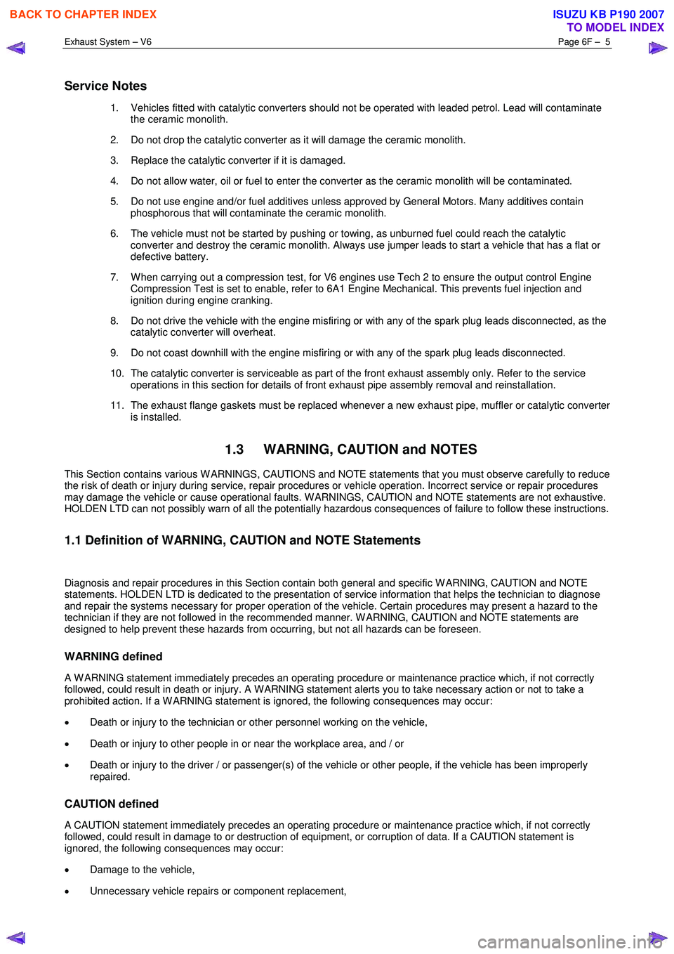
Service Notes
1. Vehicles fitted with catalytic converters should not be operated with leaded petrol. Lead will contaminate
the ceramic monolith.
2. Do not drop the catalytic converter as it will damage the ceramic monolith.
3. Replace the catalytic converter if it is damaged.
4. Do not allow water, oil or fuel to enter the converter as the ceramic monolith will be contaminated.
5. Do not use engine and/or fuel additives unless approved by General Motors. Many additives contain phosphorous that will contaminate the ceramic monolith.
6. The vehicle must not be started by pushing or towing, as unburned fuel could reach the catalytic converter and destroy the ceramic monolith. Always use jumper leads to start a vehicle that has a flat or
defective battery.
7. W hen carrying out a compression test, for V6 engines use Tech 2 to ensure the output control Engine Compression Test is set to enable, refer to 6A1 Engine Mechanical. This prevents fuel injection and
ignition during engine cranking.
8. Do not drive the vehicle with the engine misfiring or with any of the spark plug leads disconnected, as the catalytic converter will overheat.
9. Do not coast downhill with the engine misfiring or with any of the spark plug leads disconnected.
10. The catalytic converter is serviceable as part of the front exhaust assembly only. Refer to the service operations in this section for details of front exhaust pipe assembly removal and reinstallation.
11. The exhaust flange gaskets must be replaced whenever a new exhaust pipe, muffler or catalytic converter is installed.
1.3 WARNING, CAUTION and NOTES
This Section contains various W ARNINGS, CAUTIONS and NOTE statements that you must observe carefully to reduce
the risk of death or injury during service, repair procedures or vehicle operation. Incorrect service or repair procedures
may damage the vehicle or cause operational faults. W ARNINGS, CAUTION and NOTE statements are not exhaustive.
HOLDEN LTD can not possibly warn of all the potentially hazardous consequences of failure to follow these instructions.
1.1 Definition of WARNING, CAUTION and NOTE Statements
Diagnosis and repair procedures in this Section contain both general and specific W ARNING, CAUTION and NOTE
statements. HOLDEN LTD is dedicated to the presentation of service information that helps the technician to diagnose
and repair the systems necessary for proper operation of the vehicle. Certain procedures may present a hazard to the
technician if they are not followed in the recommended manner. W ARNING, CAUTION and NOTE statements are
designed to help prevent these hazards from occurring, but not all hazards can be foreseen.
WARNING defined
A W ARNING statement immediately precedes an operating procedure or maintenance practice which, if not correctly
followed, could result in death or injury. A W ARNING statement alerts you to take necessary action or not to take a
prohibited action. If a W ARNING statement is ignored, the following consequences may occur:
• Death or injury to the technician or other personnel working on the vehicle,
• Death or injury to other people in or near the workplace area, and / or
• Death or injury to the driver / or passenger(s) of the vehicle or other people, if the vehicle has been improperly
repaired.
CAUTION defined
A CAUTION statement immediately precedes an operating procedure or maintenance practice which, if not correctly
followed, could result in damage to or destruction of equipment, or corruption of data. If a CAUTION statement is
ignored, the following consequences may occur:
• Damage to the vehicle,
• Unnecessary vehicle repairs or component replacement,
BACK TO CHAPTER INDEX
TO MODEL INDEX
ISUZU KB P190 2007
Page 3892 of 6020
Automatic Transmission – 4L60E – Electrical Diagnosis Page 7C2–106
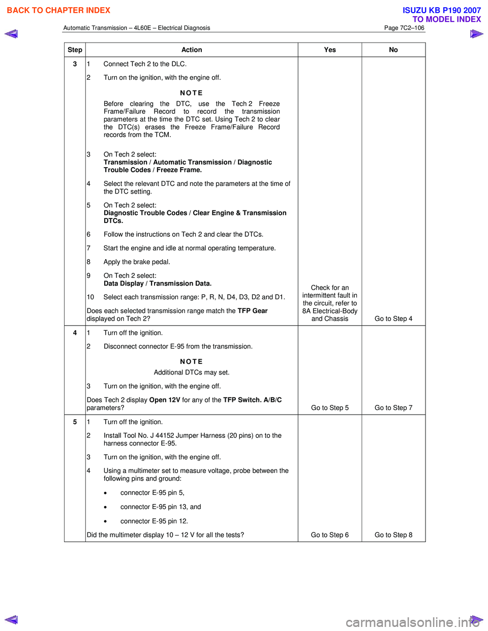
Step Action Yes No
3 1 Connect Tech 2 to the DLC.
2 Turn on the ignition, with the engine off.
NOTE
Before clearing the DTC, use the Tech 2 Freeze
Frame/Failure Record to record the transmission
parameters at the time the DTC set. Using Tech 2 to clear
the DTC(s) erases the Freeze Frame/Failure Record
records from the TCM.
3 On Tech 2 select: Transmission / Automatic Transmission / Diagnostic
Trouble Codes / Freeze Frame.
4 Select the relevant DTC and note the parameters at the time of the DTC setting.
5 On Tech 2 select:
Diagnostic Trouble Codes / Clear Engine & Transmission
DTCs.
6 Follow the instructions on Tech 2 and clear the DTCs.
7 Start the engine and idle at normal operating temperature.
8 Apply the brake pedal.
9 On Tech 2 select: Data Display / Transmission Data.
10 Select each transmission range: P, R, N, D4, D3, D2 and D1.
Does each selected transmission range match the TFP Gear
displayed on Tech 2? Check for an
intermittent fault in
the circuit, refer to
8A Electrical-Body and Chassis Go to Step 4
4 1 Turn off the ignition.
2 Disconnect connector E-95 from the transmission.
NOTE
Additional DTCs may set.
3 Turn on the ignition, with the engine off.
Does Tech 2 display Open 12V for any of the TFP Switch. A/B/C
parameters? Go to Step 5 Go to Step 7
5 1 Turn off the ignition.
2 Install Tool No. J 44152 Jumper Harness (20 pins) on to the harness connector E-95.
3 Turn on the ignition, with the engine off.
4 Using a multimeter set to measure voltage, probe between the following pins and ground:
• connector E-95 pin 5,
• connector E-95 pin 13, and
• connector E-95 pin 12.
Did the multimeter display 10 – 12 V for all the tests? Go to Step 6 Go to Step 8
BACK TO CHAPTER INDEX
TO MODEL INDEX
ISUZU KB P190 2007
Page 4014 of 6020
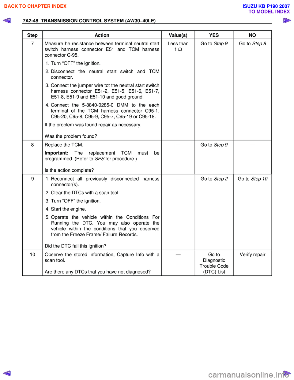
7A2-48 TRANSMISSION CONTROL SYSTEM (AW30–40LE)
Step Action Value(s) YES NO
7 Measure he resistance between terminal neutral start
switch harness connector E51 and TCM harness
connector C-95.
1. Turn “OFF” the ignition.
2. Disconnect the neutral start switch and TCM connector.
3. Connect the jumper wire tot the neutral start switch harness connector E51-2, E51-5, E51-6, E51-7,
E51-8, E51-9 and E51-10 and good ground.
4. Connect the 5-8840-0285-0 DMM to the each terminal of the TCM harness connector C95-1,
C95-20, C95-8, C95-9, C95-7, C95-19 or C95-18.
If the problem was found repair as necessary.
W as the problem found? Less than
1 Ω
Go to Step 9 Go to Step 8
8 Replace the TCM.
Important: The replacement TCM must be
programmed. (Refer to SPS for procedure.)
Is the action complete? — Go to
Step 9 —
9 1. Reconnect all previously disconnected harness
connector(s).
2. Clear the DTCs with a scan tool.
3. Turn “OFF” the ignition.
4. Start the engine.
5. Operate the vehicle within the Conditions For Running the DTC. You may also operate the
vehicle within the conditions that you observed
from the Freeze Frame/ Failure Records.
Did the DTC fail this ignition? — Go to
Step 2 Go to Step 10
10 Observe the stored information, Capture Info with a
scan tool.
Are there any DTCs that you have not diagnosed? — Go
to
Diagnostic
Trouble Code (DTC) List Verify repair
BACK TO CHAPTER INDEX
TO MODEL INDEX
ISUZU KB P190 2007
Page 4017 of 6020
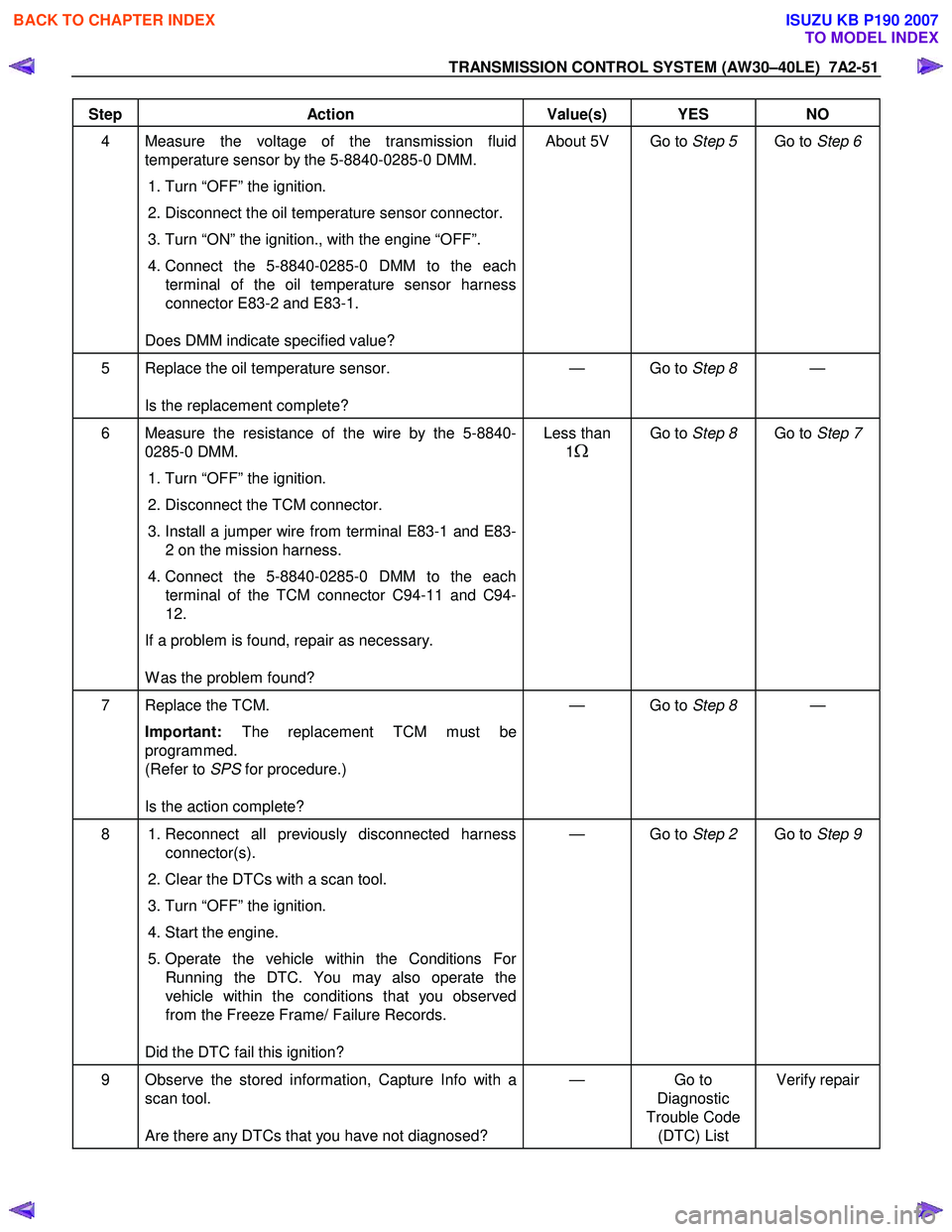
TRANSMISSION CONTROL SYSTEM (AW30–40LE) 7A2-51
Step Action Value(s) YES NO
4 Measure the voltage of the transmission fluid
temperature sensor by the 5-8840-0285-0 DMM.
1. Turn “OFF” the ignition.
2. Disconnect the oil temperature sensor connector.
3. Turn “ON” the ignition., with the engine “OFF”.
4. Connect the 5-8840-0285-0 DMM to the each
terminal of the oil temperature sensor harness
connector E83-2 and E83-1.
Does DMM indicate specified value? About 5V Go to
Step 5 Go to Step 6
5 Replace the oil temperature sensor.
Is the replacement complete? — Go to
Step 8 —
6 Measure the resistance of the wire by the 5-8840-
0285-0 DMM.
1. Turn “OFF” the ignition.
2. Disconnect the TCM connector.
3. Install a jumper wire from terminal E83-1 and E83-
2 on the mission harness.
4. Connect the 5-8840-0285-0 DMM to the each
terminal of the TCM connector C94-11 and C94-
12.
If a problem is found, repair as necessary.
W as the problem found? Less than
1
Ω
Go to Step 8 Go to Step 7
7 Replace the TCM.
Important: The replacement TCM must be
programmed.
(Refer to SPS for procedure.)
Is the action complete? — Go to
Step 8 —
8 1. Reconnect all previously disconnected harness
connector(s).
2. Clear the DTCs with a scan tool.
3. Turn “OFF” the ignition.
4. Start the engine.
5. Operate the vehicle within the Conditions For Running the DTC. You may also operate the
vehicle within the conditions that you observed
from the Freeze Frame/ Failure Records.
Did the DTC fail this ignition? — Go to
Step 2 Go to Step 9
9 Observe the stored information, Capture Info with a
scan tool.
Are there any DTCs that you have not diagnosed? — Go
to
Diagnostic
Trouble Code (DTC) List Verify repair
BACK TO CHAPTER INDEX
TO MODEL INDEX
ISUZU KB P190 2007
Page 4019 of 6020
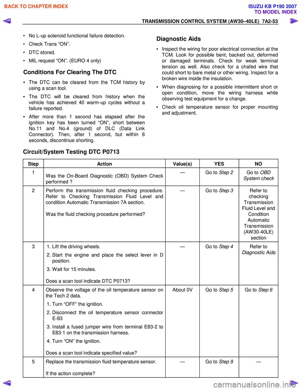
TRANSMISSION CONTROL SYSTEM (AW30–40LE) 7A2-53
• No L-up solenoid functional failure detection.
• Check Trans “ON”.
• DTC stored.
• MIL request “ON”. (EURO 4 only)
Conditions For Clearing The DTC
• The DTC can be cleared from the TCM history by
using a scan tool.
• The DTC will be cleared from history when the
vehicle has achieved 40 warm-up cycles without a
failure reported.
•
After more than 1 second has elapsed after the
ignition key has been turned “ON”, short between
No.11 and No.4 (ground) of DLC (Data Link
Connector). Then, after 1 second, but within 6
seconds, discontinue shorting.
Diagnostic Aids
•
Inspect the wiring for poor electrical connection at the
TCM. Look for possible bent, backed out, deformed
or damaged terminals. Check for weak terminal
tension as well. Also check for a chafed wire that
could short to bare metal or other wiring. Inspect for a
broken wire inside the insulation.
• W hen diagnosing for a possible intermittent short o
r
open condition, move the wiring harness while
observing test equipment for a change.
• Check oil temperature sensor for proper mounting
and adjustment.
Circuit/System Testing DTC P0713
Step Action Value(s) YES NO
1
W as the On-Board Diagnostic (OBD) System Check
performed ? — Go to
Step 2 Go to OBD
System check
2 Perform the transmission fluid checking procedure. Refer to Checking Transmission Fluid Level and
condition Automatic Transmission 7A section.
W as the fluid checking procedure performed? — Go to
Step 3 Refer to
checking
Transmission
Fluid Level and Condition
Automatic
Transmission
(AW 30-40LE) section
3 1. Lift the driving wheels.
2. Start the engine and place the select lever in D
position.
3. W ait for 15 minutes.
Does a scan tool indicate DTC P0713? — Go to
Step 4 Refer to
Diagnostic Aids
4 Observe the voltage of the oil temperature sensor on the Tech 2 data.
1. Turn “OFF” the ignition.
2. Disconnect the oil temperature sensor connector
E-83
3. Install a fused jumper wire from terminal E83-2 to E83-1 on the transmission harness.
4. Turn “ON” the ignition.
Does a scan tool indicate specified value? About 0V Go to
Step 5 Go to Step 6
5 Replace the transmission fluid temperature sensor.
If the action complete? — Go to
Step 9 —
BACK TO CHAPTER INDEX
TO MODEL INDEX
ISUZU KB P190 2007