2007 ISUZU KB P190 jump start
[x] Cancel search: jump startPage 1797 of 6020
6E-180 ENGINE CONTROL SYSTEM (4JK1/4JJ1)
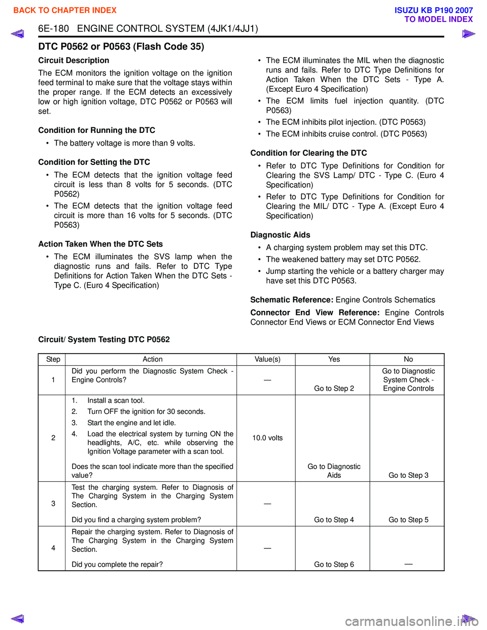
DTC P0562 or P0563 (Flash Code 35)
Circuit Description
The ECM monitors the ignition voltage on the ignition
feed terminal to make sure that the voltage stays within
the proper range. If the ECM detects an excessively
low or high ignition voltage, DTC P0562 or P0563 will
set.
Condition for Running the DTC • The battery voltage is more than 9 volts.
Condition for Setting the DTC • The ECM detects that the ignition voltage feed circuit is less than 8 volts for 5 seconds. (DTC
P0562)
• The ECM detects that the ignition voltage feed circuit is more than 16 volts for 5 seconds. (DTC
P0563)
Action Taken When the DTC Sets • The ECM illuminates the SVS lamp when the diagnostic runs and fails. Refer to DTC Type
Definitions for Action Taken When the DTC Sets -
Type C. (Euro 4 Specification) • The ECM illuminates the MIL when the diagnostic
runs and fails. Refer to DTC Type Definitions for
Action Taken When the DTC Sets - Type A.
(Except Euro 4 Specification)
• The ECM limits fuel injection quantity. (DTC P0563)
• The ECM inhibits pilot injection. (DTC P0563)
• The ECM inhibits cruise control. (DTC P0563)
Condition for Clearing the DTC • Refer to DTC Type Definitions for Condition for Clearing the SVS Lamp/ DTC - Type C. (Euro 4
Specification)
• Refer to DTC Type Definitions for Condition for Clearing the MIL/ DTC - Type A. (Except Euro 4
Specification)
Diagnostic Aids • A charging system problem may set this DTC.
• The weakened battery may set DTC P0562.
• Jump starting the vehicle or a battery charger may have set this DTC P0563.
Schematic Reference: Engine Controls Schematics
Connector End View Reference: Engine Controls
Connector End Views or ECM Connector End Views
Circuit/ System Testing DTC P0562
Step Action Value(s)Yes No
1 Did you perform the Diagnostic System Check -
Engine Controls? —
Go to Step 2 Go to Diagnostic
System Check -
Engine Controls
2 1. Install a scan tool.
2. Turn OFF the ignition for 30 seconds.
3. Start the engine and let idle.
4. Load the electrical system by turning ON the headlights, A/C, etc. while observing the
Ignition Voltage parameter with a scan tool.
Does the scan tool indicate more than the specified
value? 10.0 volts
Go to Diagnostic Aids Go to Step 3
3 Test the charging system. Refer to Diagnosis of
The Charging System in the Charging System
Section.
Did you find a charging system problem? —
Go to Step 4 Go to Step 5
4 Repair the charging system. Refer to Diagnosis of
The Charging System in the Charging System
Section.
Did you complete the repair? —
Go to Step 6
—
BACK TO CHAPTER INDEX
TO MODEL INDEX
ISUZU KB P190 2007
Page 1798 of 6020

ENGINE CONTROL SYSTEM (4JK1/4JJ1) 6E-181
Circuit/ System Testing DTC P0563
51. Turn OFF the ignition.
2. Disconnect the ECM harness connector.
3. Inspect for an intermittent, for a poor connection and for corrosion at the harness
connector of the ECM (pin 72 of C-58).
4. Repair the connection(s) as necessary.
Did you find and correct the condition? —
Go to Step 6 Go to Diagnostic
Aids
6 1. Reconnect all previously disconnected
harness connector(s).
2. Clear the DTCs with a scan tool.
3. Turn OFF the ignition for 30 seconds.
4. Start the engine and let idle.
5. Load the electrical system by turning ON the headlights, A/C, etc. while observing the
Ignition Voltage parameter with a scan tool.
Does the scan tool indicate more than the specified
value? 10.0 volts
Go to Step 7 Go to Step 3
7 Observe the DTC Information with a scan tool.
Are there any DTCs that you have not diagnosed? —
Go to DTC List System OK
Step
Action Value(s)Yes No
Step Action Value(s)Yes No
1 Did you perform the Diagnostic System Check -
Engine Controls? —
Go to Step 2 Go to Diagnostic
System Check -
Engine Controls
2 Was the vehicle recently jump started or a battery
charger placed on the battery? —
Go to Step 7 Go to Step 3
3 1. Install a scan tool.
2. Start the engine and let idle.
3. Observe the Ignition Voltage parameter with the scan tool.
Does the scan tool indicate less than the specified
value? 16.0 volts
Go to Diagnostic Aids Go to Step 4
4 Test the charging system. Refer to Diagnosis of
The Charging System in the Charging System
Section.
Did you find a charging system problem? —
Go to Step 5 Go to Diagnostic
Aids
5 Repair the charging system. Refer to Diagnosis of
The Charging System in the Charging System
Section.
Did you complete the repair? —
Go to Step 6
—
BACK TO CHAPTER INDEX
TO MODEL INDEX
ISUZU KB P190 2007
Page 1867 of 6020
6E-250 ENGINE CONTROL SYSTEM (4JK1/4JJ1)
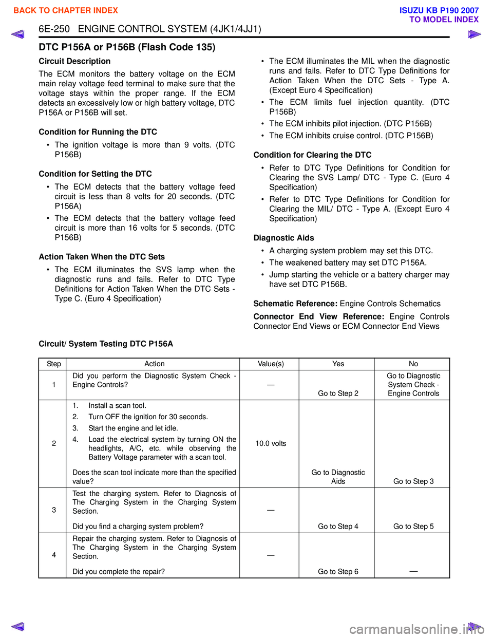
DTC P156A or P156B (Flash Code 135)
Circuit Description
The ECM monitors the battery voltage on the ECM
main relay voltage feed terminal to make sure that the
voltage stays within the proper range. If the ECM
detects an excessively low or high battery voltage, DTC
P156A or P156B will set.
Condition for Running the DTC • The ignition voltage is more than 9 volts. (DTC P156B)
Condition for Setting the DTC • The ECM detects that the battery voltage feed circuit is less than 8 volts for 20 seconds. (DTC
P156A)
• The ECM detects that the battery voltage feed circuit is more than 16 volts for 5 seconds. (DTC
P156B)
Action Taken When the DTC Sets • The ECM illuminates the SVS lamp when the diagnostic runs and fails. Refer to DTC Type
Definitions for Action Taken When the DTC Sets -
Type C. (Euro 4 Specification) • The ECM illuminates the MIL when the diagnostic
runs and fails. Refer to DTC Type Definitions for
Action Taken When the DTC Sets - Type A.
(Except Euro 4 Specification)
• The ECM limits fuel injection quantity. (DTC P156B)
• The ECM inhibits pilot injection. (DTC P156B)
• The ECM inhibits cruise control. (DTC P156B)
Condition for Clearing the DTC • Refer to DTC Type Definitions for Condition for Clearing the SVS Lamp/ DTC - Type C. (Euro 4
Specification)
• Refer to DTC Type Definitions for Condition for Clearing the MIL/ DTC - Type A. (Except Euro 4
Specification)
Diagnostic Aids • A charging system problem may set this DTC.
• The weakened battery may set DTC P156A.
• Jump starting the vehicle or a battery charger may have set DTC P156B.
Schematic Reference: Engine Controls Schematics
Connector End View Reference: Engine Controls
Connector End Views or ECM Connector End Views
Circuit/ System Testing DTC P156A
Step Action Value(s)Yes No
1 Did you perform the Diagnostic System Check -
Engine Controls? —
Go to Step 2 Go to Diagnostic
System Check -
Engine Controls
2 1. Install a scan tool.
2. Turn OFF the ignition for 30 seconds.
3. Start the engine and let idle.
4. Load the electrical system by turning ON the headlights, A/C, etc. while observing the
Battery Voltage parameter with a scan tool.
Does the scan tool indicate more than the specified
value? 10.0 volts
Go to Diagnostic Aids Go to Step 3
3 Test the charging system. Refer to Diagnosis of
The Charging System in the Charging System
Section.
Did you find a charging system problem? —
Go to Step 4 Go to Step 5
4 Repair the charging system. Refer to Diagnosis of
The Charging System in the Charging System
Section.
Did you complete the repair? —
Go to Step 6
—
BACK TO CHAPTER INDEX
TO MODEL INDEX
ISUZU KB P190 2007
Page 1868 of 6020
ENGINE CONTROL SYSTEM (4JK1/4JJ1) 6E-251
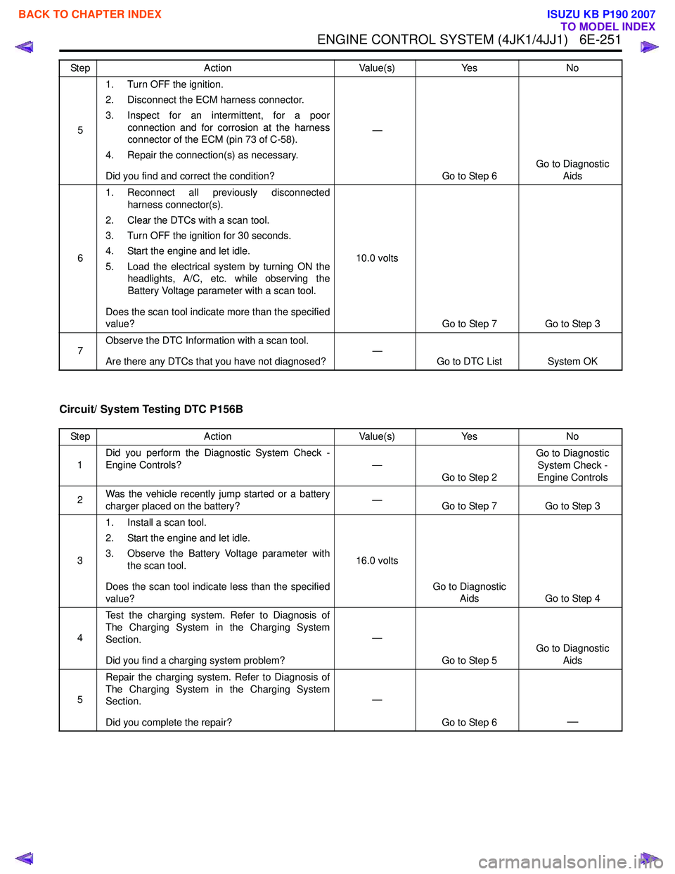
Circuit/ System Testing DTC P156B
51. Turn OFF the ignition.
2. Disconnect the ECM harness connector.
3. Inspect for an intermittent, for a poor connection and for corrosion at the harness
connector of the ECM (pin 73 of C-58).
4. Repair the connection(s) as necessary.
Did you find and correct the condition? —
Go to Step 6 Go to Diagnostic
Aids
6 1. Reconnect all previously disconnected
harness connector(s).
2. Clear the DTCs with a scan tool.
3. Turn OFF the ignition for 30 seconds.
4. Start the engine and let idle.
5. Load the electrical system by turning ON the headlights, A/C, etc. while observing the
Battery Voltage parameter with a scan tool.
Does the scan tool indicate more than the specified
value? 10.0 volts
Go to Step 7 Go to Step 3
7 Observe the DTC Information with a scan tool.
Are there any DTCs that you have not diagnosed? —
Go to DTC List System OK
Step
Action Value(s)Yes No
Step Action Value(s)Yes No
1 Did you perform the Diagnostic System Check -
Engine Controls? —
Go to Step 2 Go to Diagnostic
System Check -
Engine Controls
2 Was the vehicle recently jump started or a battery
charger placed on the battery? —
Go to Step 7 Go to Step 3
3 1. Install a scan tool.
2. Start the engine and let idle.
3. Observe the Battery Voltage parameter with the scan tool.
Does the scan tool indicate less than the specified
value? 16.0 volts
Go to Diagnostic Aids Go to Step 4
4 Test the charging system. Refer to Diagnosis of
The Charging System in the Charging System
Section.
Did you find a charging system problem? —
Go to Step 5 Go to Diagnostic
Aids
5 Repair the charging system. Refer to Diagnosis of
The Charging System in the Charging System
Section.
Did you complete the repair? —
Go to Step 6
—
BACK TO CHAPTER INDEX
TO MODEL INDEX
ISUZU KB P190 2007
Page 1886 of 6020
ENGINE CONTROL SYSTEM (4JK1/4JJ1) 6E-269
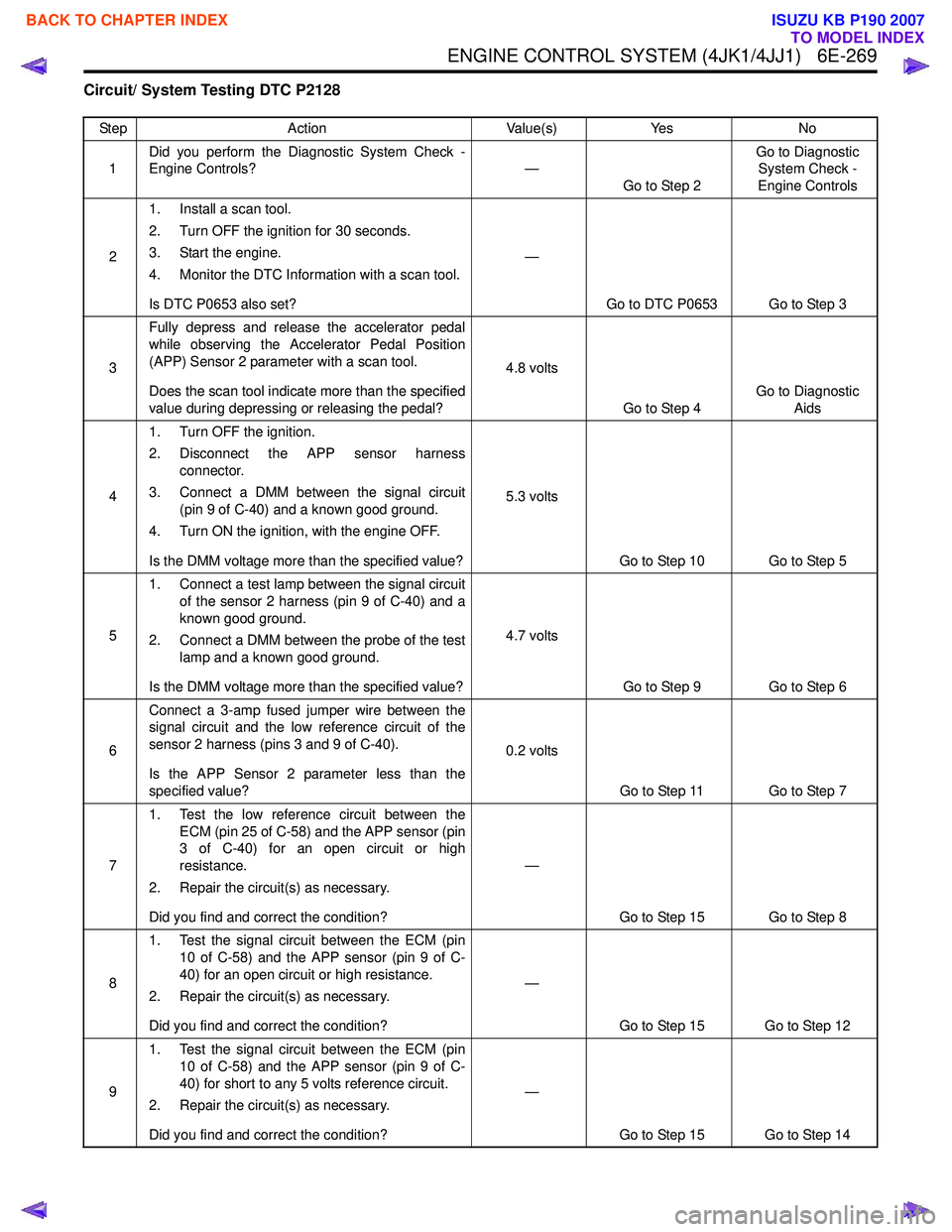
Circuit/ System Testing DTC P2128
StepAction Value(s)Yes No
1 Did you perform the Diagnostic System Check -
Engine Controls? —
Go to Step 2 Go to Diagnostic
System Check -
Engine Controls
2 1. Install a scan tool.
2. Turn OFF the ignition for 30 seconds.
3. Start the engine.
4. Monitor the DTC Information with a scan tool.
Is DTC P0653 also set? —
Go to DTC P0653 Go to Step 3
3 Fully depress and release the accelerator pedal
while observing the Accelerator Pedal Position
(APP) Sensor 2 parameter with a scan tool.
Does the scan tool indicate more than the specified
value during depressing or releasing the pedal? 4.8 volts
Go to Step 4 Go to Diagnostic
Aids
4 1. Turn OFF the ignition.
2. Disconnect the APP sensor harness connector.
3. Connect a DMM between the signal circuit (pin 9 of C-40) and a known good ground.
4. Turn ON the ignition, with the engine OFF.
Is the DMM voltage more than the specified value? 5.3 volts
Go to Step 10 Go to Step 5
5 1. Connect a test lamp between the signal circuit
of the sensor 2 harness (pin 9 of C-40) and a
known good ground.
2. Connect a DMM between the probe of the test lamp and a known good ground.
Is the DMM voltage more than the specified value? 4.7 volts
Go to Step 9 Go to Step 6
6 Connect a 3-amp fused jumper wire between the
signal circuit and the low reference circuit of the
sensor 2 harness (pins 3 and 9 of C-40).
Is the APP Sensor 2 parameter less than the
specified value? 0.2 volts
Go to Step 11 Go to Step 7
7 1. Test the low reference circuit between the
ECM (pin 25 of C-58) and the APP sensor (pin
3 of C-40) for an open circuit or high
resistance.
2. Repair the circuit(s) as necessary.
Did you find and correct the condition? —
Go to Step 15 Go to Step 8
8 1. Test the signal circuit between the ECM (pin
10 of C-58) and the APP sensor (pin 9 of C-
40) for an open circuit or high resistance.
2. Repair the circuit(s) as necessary.
Did you find and correct the condition? —
Go to Step 15 Go to Step 12
9 1. Test the signal circuit between the ECM (pin
10 of C-58) and the APP sensor (pin 9 of C-
40) for short to any 5 volts reference circuit.
2. Repair the circuit(s) as necessary.
Did you find and correct the condition? —
Go to Step 15 Go to Step 14
BACK TO CHAPTER INDEX
TO MODEL INDEX
ISUZU KB P190 2007
Page 1890 of 6020
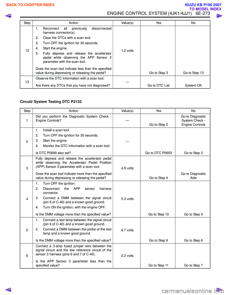
ENGINE CONTROL SYSTEM (4JK1/4JJ1) 6E-273
Circuit/ System Testing DTC P2133
121. Reconnect all previously disconnected
harness connector(s).
2. Clear the DTCs with a scan tool.
3. Turn OFF the ignition for 30 seconds.
4. Start the engine.
5. Fully depress and release the accelerator pedal while observing the APP Sensor 3
parameter with the scan tool.
Does the scan tool indicate less than the specified
value during depressing or releasing the pedal? 1.2 volts
Go to Step 3 Go to Step 13
13 Observe the DTC Information with a scan tool.
Are there any DTCs that you have not diagnosed? —
Go to DTC List System OK
Step Action Value(s) Yes No
Step
Action Value(s)Yes No
1 Did you perform the Diagnostic System Check -
Engine Controls? —
Go to Step 2 Go to Diagnostic
System Check -
Engine Controls
2 1. Install a scan tool.
2. Turn OFF the ignition for 30 seconds.
3. Start the engine.
4. Monitor the DTC Information with a scan tool.
Is DTC P0699 also set? —
Go to DTC P0653 Go to Step 3
3 Fully depress and release the accelerator pedal
while observing the Accelerator Pedal Position
(APP) Sensor 3 parameter with a scan tool.
Does the scan tool indicate more than the specified
value during depressing or releasing the pedal? 4.8 volts
Go to Step 4 Go to Diagnostic
Aids
4 1. Turn OFF the ignition.
2. Disconnect the APP sensor harness connector.
3. Connect a DMM between the signal circuit (pin 6 of C-40) and a known good ground.
4. Turn ON the ignition, with the engine OFF.
Is the DMM voltage more than the specified value? 5.3 volts
Go to Step 10 Go to Step 5
5 1. Connect a test lamp between the signal circuit
(pin 6 of C-40) and a known good ground.
2. Connect a DMM between the probe of the test lamp and a known good ground.
Is the DMM voltage more than the specified value? 4.7 volts
Go to Step 9 Go to Step 6
6 Connect a 3-amp fused jumper wire between the
signal circuit and the low reference circuit of the
sensor 3 harness (pins 6 and 7 of C-40).
Is the APP Sensor 3 parameter less than the
specified value? 0.2 volts
Go to Step 11 Go to Step 7
BACK TO CHAPTER INDEX
TO MODEL INDEX
ISUZU KB P190 2007
Page 1911 of 6020
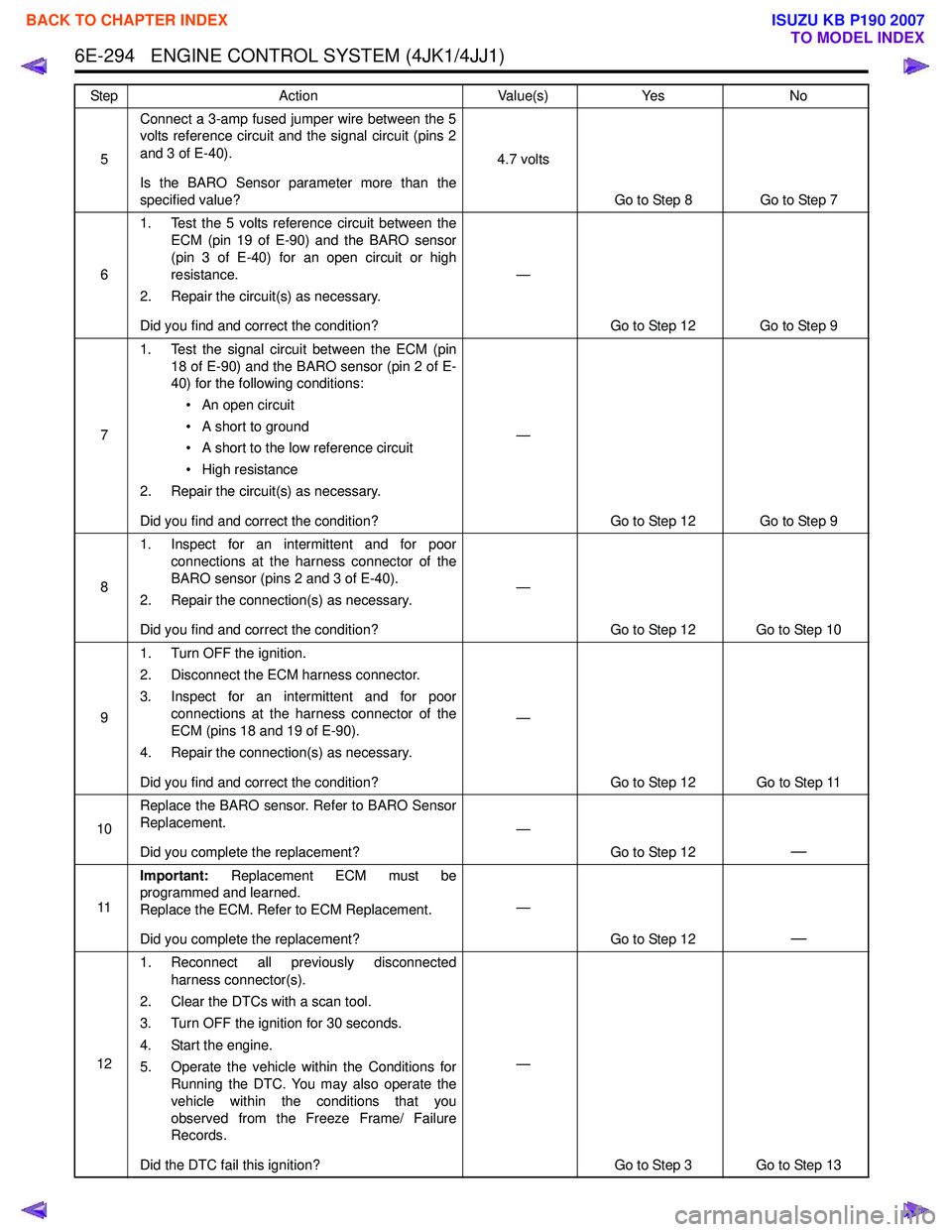
6E-294 ENGINE CONTROL SYSTEM (4JK1/4JJ1)
5Connect a 3-amp fused jumper wire between the 5
volts reference circuit and the signal circuit (pins 2
and 3 of E-40).
Is the BARO Sensor parameter more than the
specified value? 4.7 volts
Go to Step 8 Go to Step 7
6 1. Test the 5 volts reference circuit between the
ECM (pin 19 of E-90) and the BARO sensor
(pin 3 of E-40) for an open circuit or high
resistance.
2. Repair the circuit(s) as necessary.
Did you find and correct the condition? —
Go to Step 12 Go to Step 9
7 1. Test the signal circuit between the ECM (pin
18 of E-90) and the BARO sensor (pin 2 of E-
40) for the following conditions:
• An open circuit
• A short to ground
• A short to the low reference circuit
• High resistance
2. Repair the circuit(s) as necessary.
Did you find and correct the condition? —
Go to Step 12 Go to Step 9
8 1. Inspect for an intermittent and for poor
connections at the harness connector of the
BARO sensor (pins 2 and 3 of E-40).
2. Repair the connection(s) as necessary.
Did you find and correct the condition? —
Go to Step 12 Go to Step 10
9 1. Turn OFF the ignition.
2. Disconnect the ECM harness connector.
3. Inspect for an intermittent and for poor connections at the harness connector of the
ECM (pins 18 and 19 of E-90).
4. Repair the connection(s) as necessary.
Did you find and correct the condition? —
Go to Step 12 Go to Step 11
10 Replace the BARO sensor. Refer to BARO Sensor
Replacement.
Did you complete the replacement? —
Go to Step 12
—
11Important:
Replacement ECM must be
programmed and learned.
Replace the ECM. Refer to ECM Replacement.
Did you complete the replacement? —
Go to Step 12
—
121. Reconnect all previously disconnected
harness connector(s).
2. Clear the DTCs with a scan tool.
3. Turn OFF the ignition for 30 seconds.
4. Start the engine.
5. Operate the vehicle within the Conditions for Running the DTC. You may also operate the
vehicle within the conditions that you
observed from the Freeze Frame/ Failure
Records.
Did the DTC fail this ignition? —
Go to Step 3 Go to Step 13
Step
Action Value(s)Yes No
BACK TO CHAPTER INDEX
TO MODEL INDEX
ISUZU KB P190 2007
Page 2002 of 6020
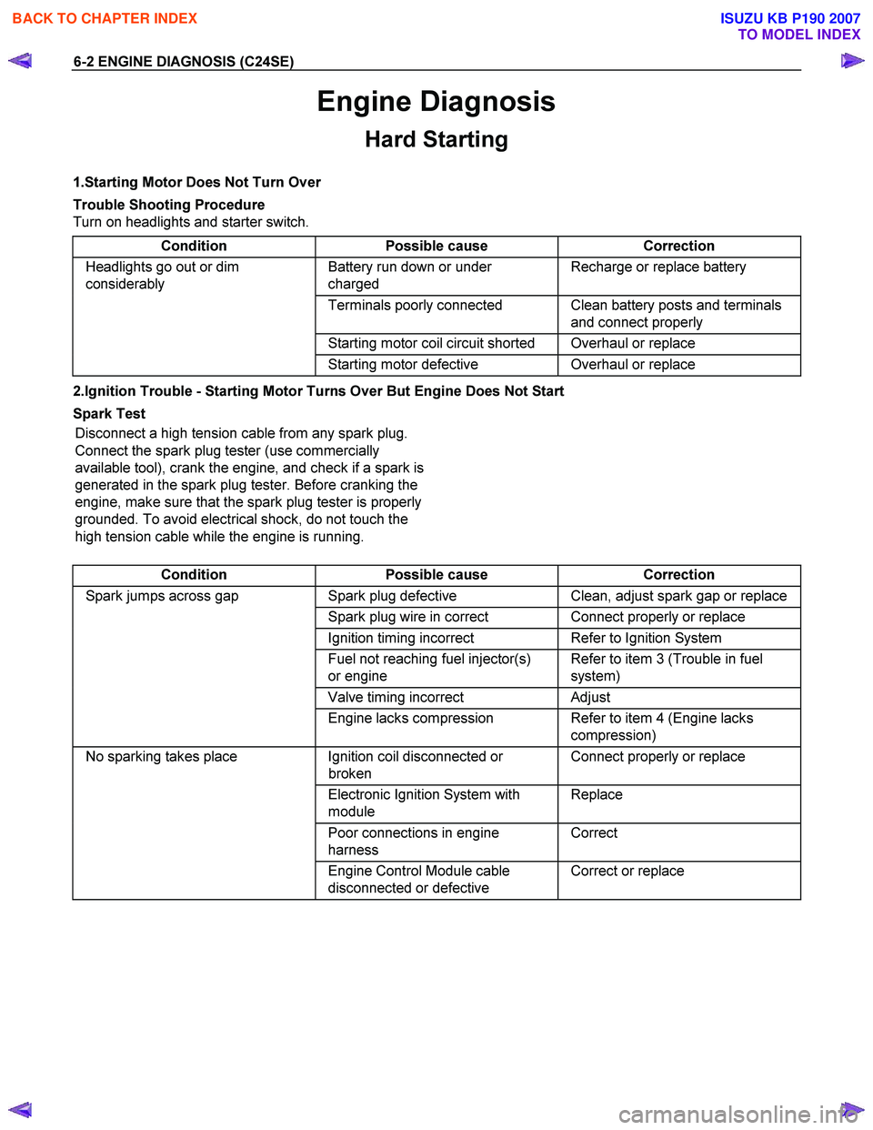
6-2 ENGINE DIAGNOSIS (C24SE)
Engine Diagnosis
Hard Starting
1.Starting Motor Does Not Turn Over
Trouble Shooting Procedure
Turn on headlights and starter switch.
Condition Possible cause Correction
Headlights go out or dim
considerably Battery run down or under
charged Recharge or replace battery
Terminals poorly connected Clean battery posts and terminals
and connect properly
Starting motor coil circuit shorted Overhaul or replace
Starting motor defective Overhaul or replace
2.Ignition Trouble - Starting Motor Turns Over But Engine Does Not Start
Spark Test Disconnect a high tension cable from any spark plug.
Connect the spark plug tester (use commercially
available tool), crank the engine, and check if a spark is
generated in the spark plug tester. Before cranking the
engine, make sure that the spark plug tester is properly
grounded. To avoid electrical shock, do not touch the
high tension cable while the engine is running.
Condition Possible cause Correction
Spark jumps across gap Spark plug defective Clean, adjust spark gap or replace
Spark plug wire in correct Connect properly or replace
Ignition timing incorrect Refer to Ignition System
Fuel not reaching fuel injector(s)
or engine Refer to item 3 (Trouble in fuel
system)
Valve timing incorrect Adjust
Engine lacks compression Refer to item 4 (Engine lacks
compression)
No sparking takes place Ignition coil disconnected or
broken Connect properly or replace
Electronic Ignition System with
module Replace
Poor connections in engine
harness Correct
Engine Control Module cable
disconnected or defective Correct or replace
BACK TO CHAPTER INDEX
TO MODEL INDEX
ISUZU KB P190 2007