2007 ISUZU KB P190 jump start
[x] Cancel search: jump startPage 1285 of 6020

Engine Control System (4JH1) 6E-251
Step Action Value(s) Yes No
16 1. Turn OFF the ignition.
2. Keep the 3-amp fused wire with connected.
3. Disconnect the ECM C-56 harness connector.
4. Connect a test lamp between the thermo relay input circuit (pin 33 of C-56 connector) and a
known good ground.
5. Turn ON the ignition, with the engine OFF. DO NOT START the engine.
Does the test lamp illuminate?
Go to Step 36 Go to Step 24
17 1. Turn OFF the ignition. 2. Keep the 3-amp fused wire with connected.
3. Replace the thermo relay with the horn relay or replace with a known good relay.
4. Connect a 3-amp fused jumper wire between the pressure switch harness (pin 1 of C-24
connector) and a known good ground.
5. Turn ON the ignition, with the engine OFF.
Does the thermo relay click (engage)?
Go to Step 31 Go to Step 25
18 1. Turn OFF the ignition. 2. Connect the pressure switch harness connector.
3. Remove the grove box in order to access electronic thermostat.
4. Disconnect the electronic thermostat harness connector (C-55).
5. Connect a 3-amp fused jumper wire between the electronic thermostat voltage feed circuit (pin 2 of
C-55 connector) and a known good ground.
6. Turn ON the ignition, with the engine OFF.
Does the thermo relay click (engage)?
Go to Step 19 Go to Step 26
19 1. Turn OFF the ignition. 2. Connect a test lamp between the electronic thermostat terminal (pin 1 of C-55 connector) and
battery voltage.
3. Turn ON the blower motor switch.
Does the test lamp illuminate?
Go to Step 20 Go to Step 27
20 1. Turn OFF the ignition. 2. Connect a test lamp between the electronic thermostat voltage feed circuit (pin 3 of C-55
connector) and a known good ground.
3. Turn ON the ignition, with the engine OFF.
Does the test lamp illuminate?
Go to Step 21 Go to Step 28
21 1. Turn OFF the ignition. 2. Connect a test lamp between the electronic thermostat terminal (pin 4 of C-55 connector) and
battery voltage.
3. Turn ON the blower motor switch.
4. Turn ON the A/C switch.
Does the test lamp illuminate?
Go to Step 33 Go to Step 22
BACK TO CHAPTER INDEX
TO MODEL INDEX
ISUZU KB P190 2007
Page 1661 of 6020
6E-44 ENGINE CONTROL SYSTEM (4JK1/4JJ1)
Diagnostic Starting Point - Engine Controls
Begin the system diagnosis with Diagnostic System
Check - Engine Controls. The Diagnostic System
Check - Engine Controls will provide the following
information:
• The identification of the control modules which command the system.
• The ability of the control modules to communicate through the serial data circuit.
• The identification of any stored diagnostic trouble codes (DTCs) and the their statuses.
The use of the Diagnostic System Check - Engine
Controls will identify the correct procedure for
diagnosing the system and where the procedure is
located.
Important: Engine Control System Check Sheet must
be used to verify the complaint vehicle, you need to
know the correct (normal) operating behavior of the
system and verify that the customer complaint is a valid
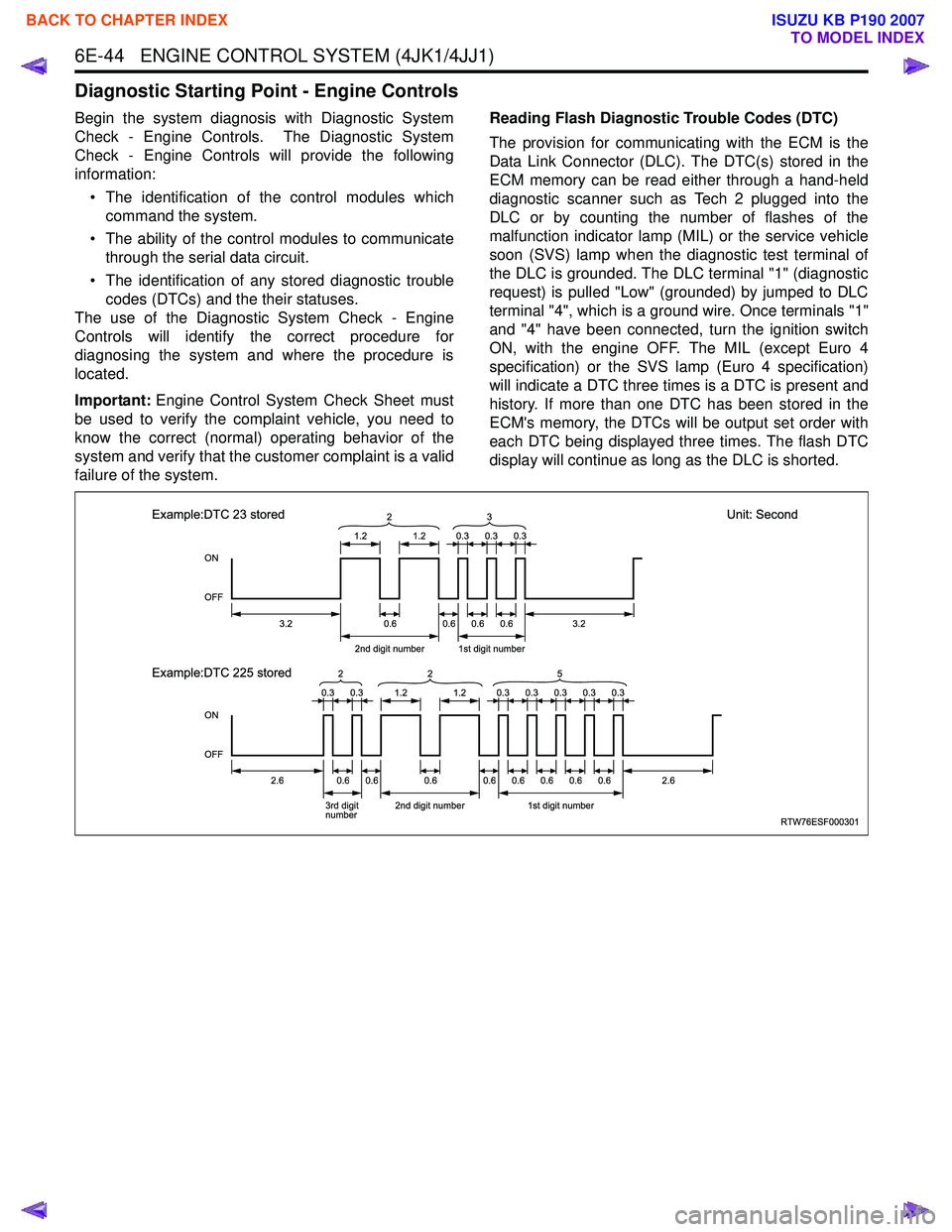
failure of the system. Reading Flash Diagnostic Trouble Codes (DTC)
The provision for communicating with the ECM is the
Data Link Connector (DLC). The DTC(s) stored in the
ECM memory can be read either through a hand-held
diagnostic scanner such as Tech 2 plugged into the
DLC or by counting the number of flashes of the
malfunction indicator lamp (MIL) or the service vehicle
soon (SVS) lamp when the diagnostic test terminal of
the DLC is grounded. The DLC terminal "1" (diagnostic
request) is pulled "Low" (grounded) by jumped to DLC
terminal "4", which is a ground wire. Once terminals "1"
and "4" have been connected, turn the ignition switch
ON, with the engine OFF. The MIL (except Euro 4
specification) or the SVS lamp (Euro 4 specification)
will indicate a DTC three times is a DTC is present and
history. If more than one DTC has been stored in the
ECM's memory, the DTCs will be output set order with
each DTC being displayed three times. The flash DTC
display will continue as long as the DLC is shorted.
RTW76ESF000301
ON
OFF
ON
OFF
1.2
3.2
2.62.6
2nd digit number1st digit number
3.20.6 2
1.2
0.60.60.6
0.30.30.3
0.30.30.30.30.3
Example:DTC 23 stored
Unit: Second
Example:DTC 225 stored
3rd digit
number 2nd digit number1st digit number
0.60.60.60.60.60.60.60.6
3
0.30.31.21.2
2
25
BACK TO CHAPTER INDEX
TO MODEL INDEX
ISUZU KB P190 2007
Page 1687 of 6020
6E-70 ENGINE CONTROL SYSTEM (4JK1/4JJ1)
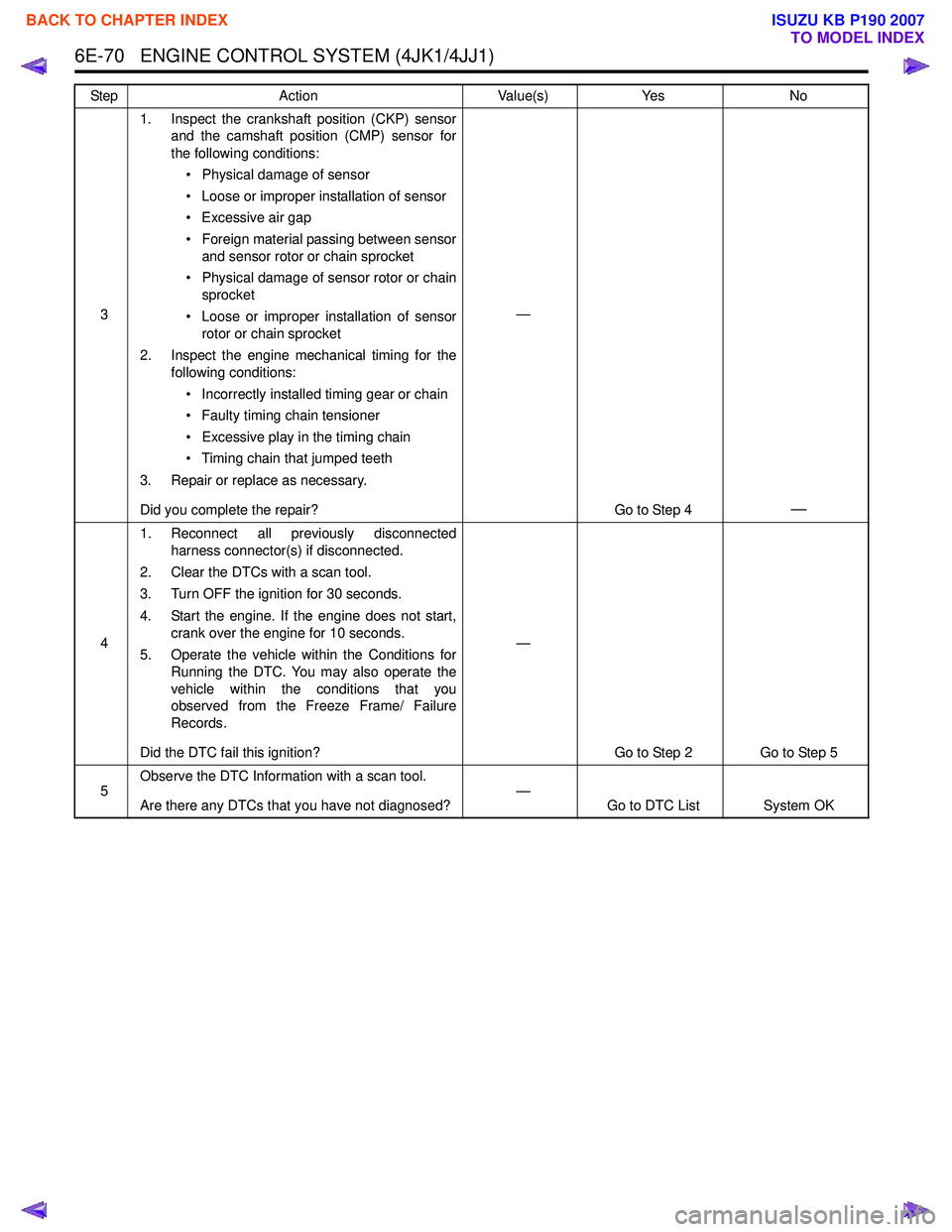
31. Inspect the crankshaft position (CKP) sensor
and the camshaft position (CMP) sensor for
the following conditions:
• Physical damage of sensor
• Loose or improper installation of sensor
• Excessive air gap
• Foreign material passing between sensor and sensor rotor or chain sprocket
• Physical damage of sensor rotor or chain sprocket
• Loose or improper installation of sensor rotor or chain sprocket
2. Inspect the engine mechanical timing for the following conditions:
• Incorrectly installed timing gear or chain
• Faulty timing chain tensioner
• Excessive play in the timing chain
• Timing chain that jumped teeth
3. Repair or replace as necessary.
Did you complete the repair? —
Go to Step 4
—
41. Reconnect all previously disconnected
harness connector(s) if disconnected.
2. Clear the DTCs with a scan tool.
3. Turn OFF the ignition for 30 seconds.
4. Start the engine. If the engine does not start, crank over the engine for 10 seconds.
5. Operate the vehicle within the Conditions for Running the DTC. You may also operate the
vehicle within the conditions that you
observed from the Freeze Frame/ Failure
Records.
Did the DTC fail this ignition? —
Go to Step 2 Go to Step 5
5 Observe the DTC Information with a scan tool.
Are there any DTCs that you have not diagnosed? —
Go to DTC List System OK
Step
Action Value(s)Yes No
BACK TO CHAPTER INDEX
TO MODEL INDEX
ISUZU KB P190 2007
Page 1715 of 6020
6E-98 ENGINE CONTROL SYSTEM (4JK1/4JJ1)
DTC P0102 or P0103 (Flash Code 91)
Circuit Description
The mass air flow (MAF) sensor is an air flow meter
that measures the amount of air that enters the engine.
It is fitted between the air cleaner and turbocharger. A
small quantity of air that enters the engine indicates
deceleration or idle speed. A large quantity of air that
enters the engine indicates acceleration or a high load
condition. The sensor has the following circuits.
• Ignition voltage circuit
• Low reference circuit
• MAF sensor signal circuit
The ECM monitors the MAF sensor signal voltage. This
output voltage will display on the scan tool as a voltage
parameter and as a grams per second (g/s) parameter.
If the ECM detects an excessively low or high signal
voltage, DTC P0102 or P0103 will set.
Condition for Running the DTC • The battery voltage is between 11.5 to 16.0 volts.
• The ignition switch is ON.
• The engine is running.
Condition for Setting the DTC • The ECM detects that the MAF sensor signal voltage is less than 0.1 volts. (DTC P0102)
• The ECM detects that the MAF sensor signal voltage is more than 4.9 volts for 3 seconds. (DTC
P0103)
Action Taken When the DTC Sets • The ECM illuminates the MIL when the diagnostic runs and fails. Refer to DTC Type Definitions for
Action Taken When the DTC Sets - Type A. • The ECM uses a MAF substitution of default value.
• The ECM limits fuel injection quantity.
• The ECM inhibits pilot injection.
• The ECM inhibits EGR control.
• The ECM inhibits cruise control.
Condition for Clearing the DTC • Refer to DTC Type Definitions for Condition for Clearing the MIL/ DTC - Type A.
Diagnostic Aids • If an intermittent condition is suspected, refer to Intermittent Conditions in this section.
Notice: • The MAF Sensor parameter on scan tool will only update with engine running or one time after the
key is cycled when the ignition has been turned
OFF for longer than 10 seconds.
Test description
The number below refers to the step number on the
Circuit/ System Testing.
DTC P0102
4. This step tests for proper operation of the circuit in
the signal circuit. If the fuse in the jumper opens when
you perform this test, the signal circuit is shorted to
ground or low reference circuits.
Schematic Reference: Engine Controls Schematics
Connector End View Reference: Engine Controls
Connector End Views or ECM Connector End Views
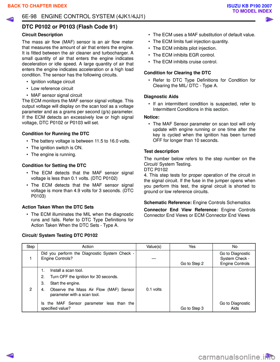
Circuit/ System Testing DTC P0102
Step Action Value(s)Yes No
1 Did you perform the Diagnostic System Check -
Engine Controls? —
Go to Step 2 Go to Diagnostic
System Check -
Engine Controls
2 1. Install a scan tool.
2. Turn OFF the ignition for 30 seconds.
3. Start the engine.
4. Observe the Mass Air Flow (MAF) Sensor parameter with a scan tool.
Is the MAF Sensor parameter less than the
specified value? 0.1 volts
Go to Step 3 Go to Diagnostic
Aids
BACK TO CHAPTER INDEX
TO MODEL INDEX
ISUZU KB P190 2007
Page 1720 of 6020
ENGINE CONTROL SYSTEM (4JK1/4JJ1) 6E-103
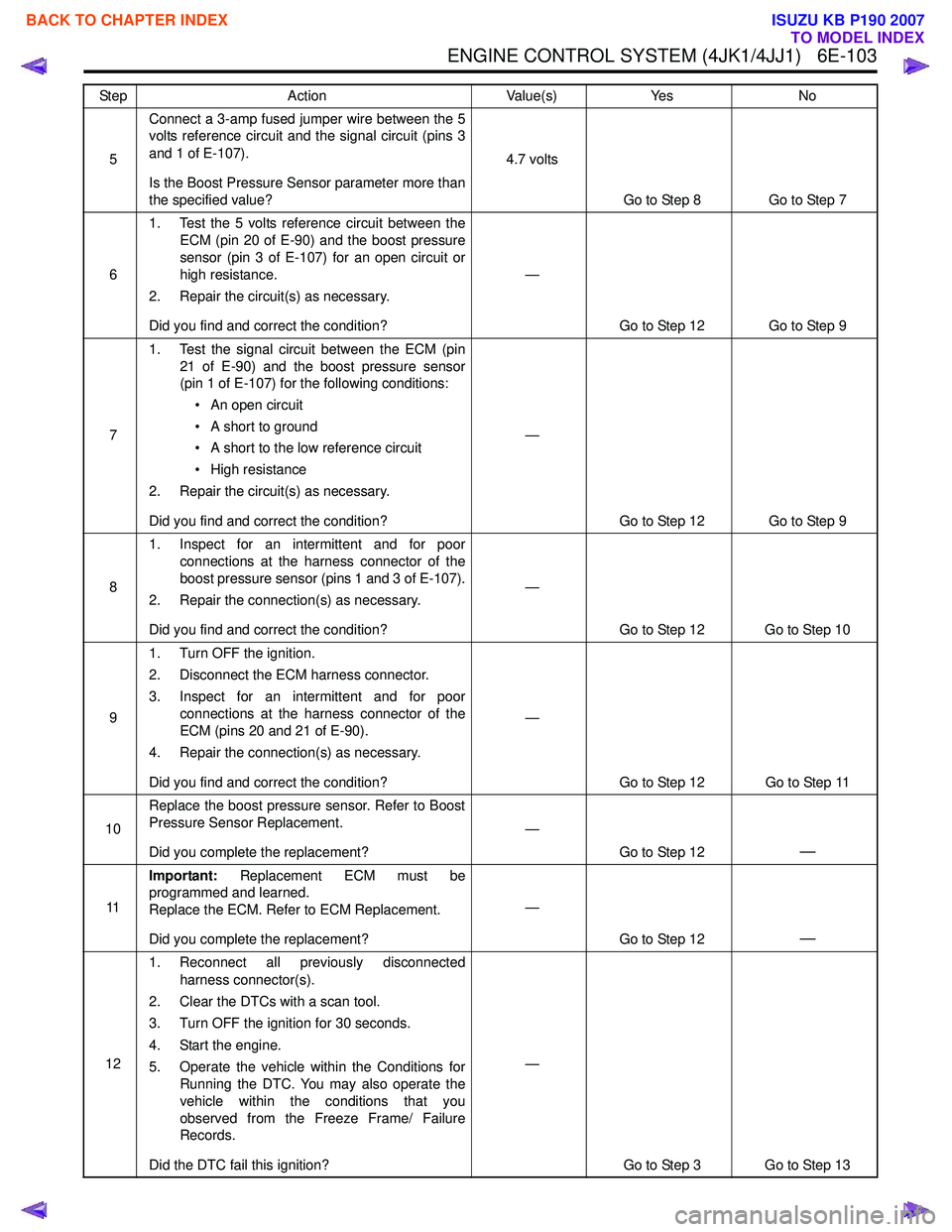
5Connect a 3-amp fused jumper wire between the 5
volts reference circuit and the signal circuit (pins 3
and 1 of E-107).
Is the Boost Pressure Sensor parameter more than
the specified value? 4.7 volts
Go to Step 8 Go to Step 7
6 1. Test the 5 volts reference circuit between the
ECM (pin 20 of E-90) and the boost pressure
sensor (pin 3 of E-107) for an open circuit or
high resistance.
2. Repair the circuit(s) as necessary.
Did you find and correct the condition? —
Go to Step 12 Go to Step 9
7 1. Test the signal circuit between the ECM (pin
21 of E-90) and the boost pressure sensor
(pin 1 of E-107) for the following conditions:
• An open circuit
• A short to ground
• A short to the low reference circuit
• High resistance
2. Repair the circuit(s) as necessary.
Did you find and correct the condition? —
Go to Step 12 Go to Step 9
8 1. Inspect for an intermittent and for poor
connections at the harness connector of the
boost pressure sensor (pins 1 and 3 of E-107).
2. Repair the connection(s) as necessary.
Did you find and correct the condition? —
Go to Step 12 Go to Step 10
9 1. Turn OFF the ignition.
2. Disconnect the ECM harness connector.
3. Inspect for an intermittent and for poor connections at the harness connector of the
ECM (pins 20 and 21 of E-90).
4. Repair the connection(s) as necessary.
Did you find and correct the condition? —
Go to Step 12 Go to Step 11
10 Replace the boost pressure sensor. Refer to Boost
Pressure Sensor Replacement.
Did you complete the replacement? —
Go to Step 12
—
11Important:
Replacement ECM must be
programmed and learned.
Replace the ECM. Refer to ECM Replacement.
Did you complete the replacement? —
Go to Step 12
—
121. Reconnect all previously disconnected
harness connector(s).
2. Clear the DTCs with a scan tool.
3. Turn OFF the ignition for 30 seconds.
4. Start the engine.
5. Operate the vehicle within the Conditions for Running the DTC. You may also operate the
vehicle within the conditions that you
observed from the Freeze Frame/ Failure
Records.
Did the DTC fail this ignition? —
Go to Step 3 Go to Step 13
Step
Action Value(s)Yes No
BACK TO CHAPTER INDEX
TO MODEL INDEX
ISUZU KB P190 2007
Page 1734 of 6020
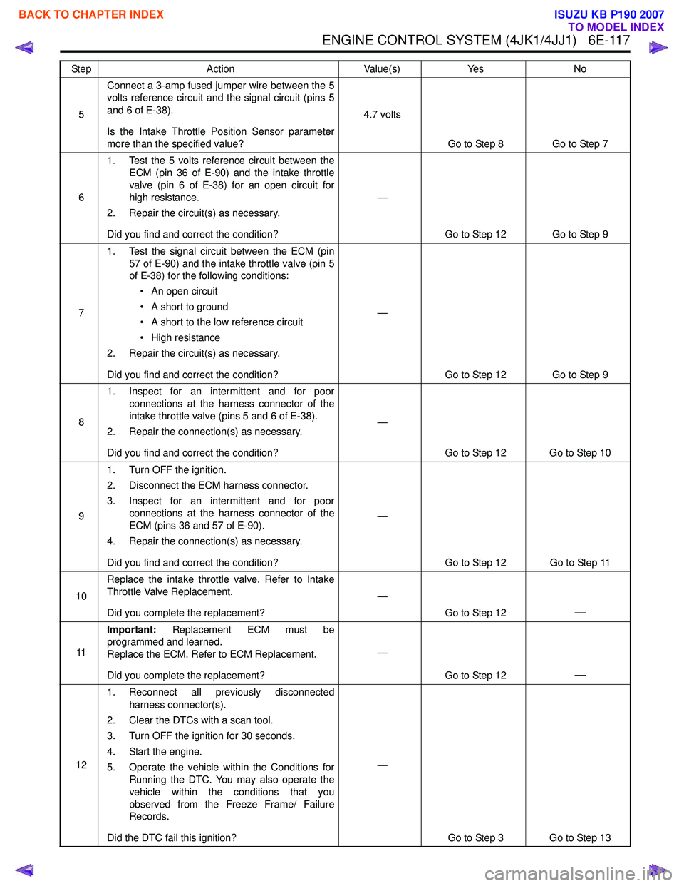
ENGINE CONTROL SYSTEM (4JK1/4JJ1) 6E-117
5Connect a 3-amp fused jumper wire between the 5
volts reference circuit and the signal circuit (pins 5
and 6 of E-38).
Is the Intake Throttle Position Sensor parameter
more than the specified value? 4.7 volts
Go to Step 8 Go to Step 7
6 1. Test the 5 volts reference circuit between the
ECM (pin 36 of E-90) and the intake throttle
valve (pin 6 of E-38) for an open circuit for
high resistance.
2. Repair the circuit(s) as necessary.
Did you find and correct the condition? —
Go to Step 12 Go to Step 9
7 1. Test the signal circuit between the ECM (pin
57 of E-90) and the intake throttle valve (pin 5
of E-38) for the following conditions:
• An open circuit
• A short to ground
• A short to the low reference circuit
• High resistance
2. Repair the circuit(s) as necessary.
Did you find and correct the condition? —
Go to Step 12 Go to Step 9
8 1. Inspect for an intermittent and for poor
connections at the harness connector of the
intake throttle valve (pins 5 and 6 of E-38).
2. Repair the connection(s) as necessary.
Did you find and correct the condition? —
Go to Step 12 Go to Step 10
9 1. Turn OFF the ignition.
2. Disconnect the ECM harness connector.
3. Inspect for an intermittent and for poor connections at the harness connector of the
ECM (pins 36 and 57 of E-90).
4. Repair the connection(s) as necessary.
Did you find and correct the condition? —
Go to Step 12 Go to Step 11
10 Replace the intake throttle valve. Refer to Intake
Throttle Valve Replacement.
Did you complete the replacement? —
Go to Step 12
—
11Important:
Replacement ECM must be
programmed and learned.
Replace the ECM. Refer to ECM Replacement.
Did you complete the replacement? —
Go to Step 12
—
121. Reconnect all previously disconnected
harness connector(s).
2. Clear the DTCs with a scan tool.
3. Turn OFF the ignition for 30 seconds.
4. Start the engine.
5. Operate the vehicle within the Conditions for Running the DTC. You may also operate the
vehicle within the conditions that you
observed from the Freeze Frame/ Failure
Records.
Did the DTC fail this ignition? —
Go to Step 3 Go to Step 13
Step
Action Value(s)Yes No
BACK TO CHAPTER INDEX
TO MODEL INDEX
ISUZU KB P190 2007
Page 1743 of 6020
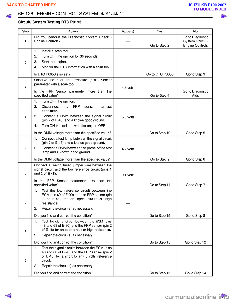
6E-126 ENGINE CONTROL SYSTEM (4JK1/4JJ1)
Circuit/ System Testing DTC P0193
StepAction Value(s)Yes No
1 Did you perform the Diagnostic System Check -
Engine Controls? —
Go to Step 2 Go to Diagnostic
System Check -
Engine Controls
2 1. Install a scan tool.
2. Turn OFF the ignition for 30 seconds.
3. Start the engine.
4. Monitor the DTC Information with a scan tool.
Is DTC P0653 also set? —
Go to DTC P0653 Go to Step 3
3 Observe the Fuel Rail Pressure (FRP) Sensor
parameter with a scan tool.
Is the FRP Sensor parameter more than the
specified value? 4.7 volts
Go to Step 4 Go to Diagnostic
Aids
4 1. Turn OFF the ignition.
2. Disconnect the FRP sensor harness connector.
3. Connect a DMM between the signal circuit (pin 2 of E-48) and a known good ground.
4. Turn ON the ignition, with the engine OFF.
Is the DMM voltage more than the specified value? 5.3 volts
Go to Step 10 Go to Step 5
5 1. Connect a test lamp between the signal circuit
(pin 2 of E-48) and a known good ground.
2. Connect a DMM between the probe of the test lamp and a known good ground.
Is the DMM voltage more than the specified value? 4.7 volts
Go to Step 9 Go to Step 6
6 Connect a 3-amp fused jumper wire between the
signal circuit and the low reference circuit (pins 1
and 2 of E-48).
Is the FRP Sensor parameter less than the
specified value? 0.1 volts
Go to Step 11 Go to Step 7
7 1. Test the low reference circuit between the
ECM (pin 69 of E-90) and the FRP sensor (pin
1 of E-48) for an open circuit or high
resistance.
2. Repair the circuit(s) as necessary.
Did you find and correct the condition? —
Go to Step 15 Go to Step 8
8 1. Test the signal circuit between the ECM (pins
48 and 68 of E-90) and the FRP sensor (pin 2
of E-48) for an open circuit or high resistance.
2. Repair the circuit(s) as necessary.
Did you find and correct the condition? —
Go to Step 15 Go to Step 12
9 1. Test the signal circuits between the ECM (pins
48 and 68 of E-90) and the FRP sensor (pin 2
of E-48) for a short to any 5 volts reference
circuit.
2. Repair the circuit(s) as necessary.
Did you find and correct the condition? —
Go to Step 15 Go to Step 14
BACK TO CHAPTER INDEX
TO MODEL INDEX
ISUZU KB P190 2007
Page 1786 of 6020
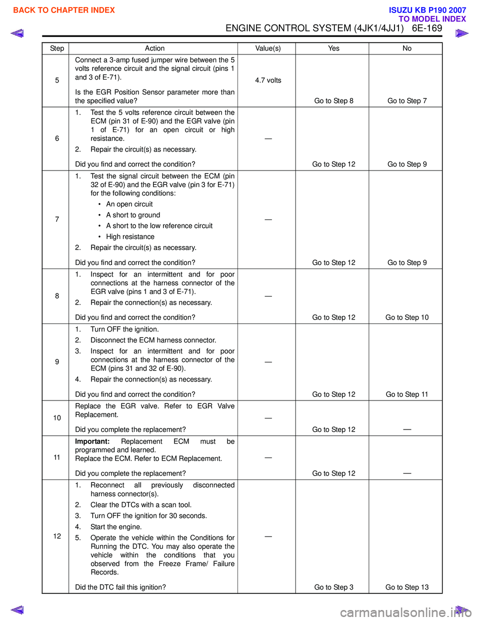
ENGINE CONTROL SYSTEM (4JK1/4JJ1) 6E-169
5Connect a 3-amp fused jumper wire between the 5
volts reference circuit and the signal circuit (pins 1
and 3 of E-71).
Is the EGR Position Sensor parameter more than
the specified value? 4.7 volts
Go to Step 8 Go to Step 7
6 1. Test the 5 volts reference circuit between the
ECM (pin 31 of E-90) and the EGR valve (pin
1 of E-71) for an open circuit or high
resistance.
2. Repair the circuit(s) as necessary.
Did you find and correct the condition? —
Go to Step 12 Go to Step 9
7 1. Test the signal circuit between the ECM (pin
32 of E-90) and the EGR valve (pin 3 for E-71)
for the following conditions:
• An open circuit
• A short to ground
• A short to the low reference circuit
• High resistance
2. Repair the circuit(s) as necessary.
Did you find and correct the condition? —
Go to Step 12 Go to Step 9
8 1. Inspect for an intermittent and for poor
connections at the harness connector of the
EGR valve (pins 1 and 3 of E-71).
2. Repair the connection(s) as necessary.
Did you find and correct the condition? —
Go to Step 12 Go to Step 10
9 1. Turn OFF the ignition.
2. Disconnect the ECM harness connector.
3. Inspect for an intermittent and for poor connections at the harness connector of the
ECM (pins 31 and 32 of E-90).
4. Repair the connection(s) as necessary.
Did you find and correct the condition? —
Go to Step 12 Go to Step 11
10 Replace the EGR valve. Refer to EGR Valve
Replacement.
Did you complete the replacement? —
Go to Step 12
—
11Important:
Replacement ECM must be
programmed and learned.
Replace the ECM. Refer to ECM Replacement.
Did you complete the replacement? —
Go to Step 12
—
121. Reconnect all previously disconnected
harness connector(s).
2. Clear the DTCs with a scan tool.
3. Turn OFF the ignition for 30 seconds.
4. Start the engine.
5. Operate the vehicle within the Conditions for Running the DTC. You may also operate the
vehicle within the conditions that you
observed from the Freeze Frame/ Failure
Records.
Did the DTC fail this ignition? —
Go to Step 3 Go to Step 13
Step
Action Value(s)Yes No
BACK TO CHAPTER INDEX
TO MODEL INDEX
ISUZU KB P190 2007