2007 ISUZU KB P190 jump start
[x] Cancel search: jump startPage 3340 of 6020
Engine Management – V6 – Diagnostics Page 6C1-2–62
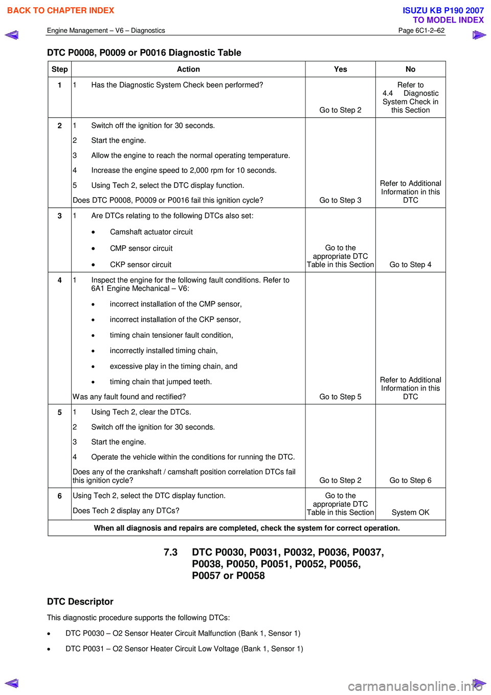
DTC P0008, P0009 or P0016 Diagnostic Table
Step Action Yes No
1 1 Has the Diagnostic System Check been performed?
Go to Step 2 Refer to
4.4 Diagnostic
System Check in this Section
2 1 Switch off the ignition for 30 seconds.
2 Start the engine.
3 Allow the engine to reach the normal operating temperature.
4 Increase the engine speed to 2,000 rpm for 10 seconds.
5 Using Tech 2, select the DTC display function.
Does DTC P0008, P0009 or P0016 fail this ignition cycle? Go to Step 3 Refer to Additional
Information in this DTC
3 1 Are DTCs relating to the following DTCs also set:
• Camshaft actuator circuit
• CMP sensor circuit
• CKP sensor circuit Go to the
appropriate DTC
Table in this Section Go to Step 4
4 1 Inspect the engine for the following fault conditions. Refer to
6A1 Engine Mechanical – V6:
• incorrect installation of the CMP sensor,
• incorrect installation of the CKP sensor,
• timing chain tensioner fault condition,
• incorrectly installed timing chain,
• excessive play in the timing chain, and
• timing chain that jumped teeth.
W as any fault found and rectified? Go to Step 5 Refer to Additional
Information in this DTC
5 1 Using Tech 2, clear the DTCs.
2 Switch off the ignition for 30 seconds.
3 Start the engine.
4 Operate the vehicle within the conditions for running the DTC.
Does any of the crankshaft / camshaft position correlation DTCs fail
this ignition cycle? Go to Step 2 Go to Step 6
6 Using Tech 2, select the DTC display function.
Does Tech 2 display any DTCs? Go to the
appropriate DTC
Table in this Section System OK
When all diagnosis and repairs are completed, check the system for correct operation.
7.3 DTC P0030, P0031, P0032, P0036, P0037,
P0038, P0050, P0051, P0052, P0056,
P0057 or P0058
DTC Descriptor
This diagnostic procedure supports the following DTCs:
• DTC P0030 – O2 Sensor Heater Circuit Malfunction (Bank 1, Sensor 1)
• DTC P0031 – O2 Sensor Heater Circuit Low Voltage (Bank 1, Sensor 1)
BACK TO CHAPTER INDEX
TO MODEL INDEX
ISUZU KB P190 2007
Page 3358 of 6020
Engine Management – V6 – Diagnostics Page 6C1-2–80
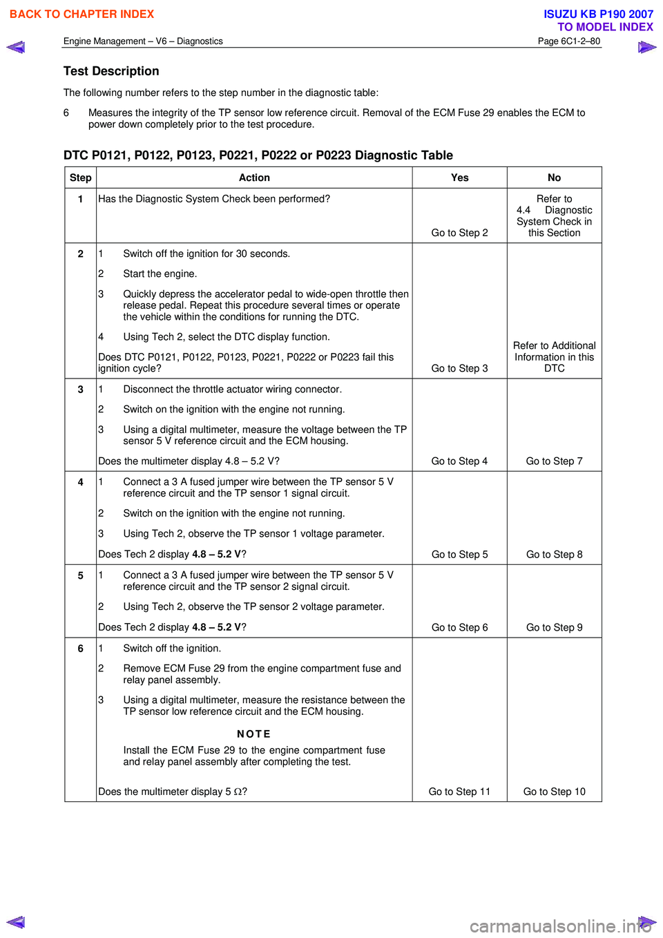
Test Description
The following number refers to the step number in the diagnostic table:
6 Measures the integrity of the TP sensor low reference circuit. Removal of the ECM Fuse 29 enables the ECM to power down completely prior to the test procedure.
DTC P0121, P0122, P0123, P0221, P0222 or P0223 Diagnostic Table
Step Action Yes No
1 Has the Diagnostic System Check been performed?
Go to Step 2 Refer to
4.4 Diagnostic
System Check in this Section
2 1 Switch off the ignition for 30 seconds.
2 Start the engine.
3 Quickly depress the accelerator pedal to wide-open throttle then release pedal. Repeat this procedure several times or operate
the vehicle within the conditions for running the DTC.
4 Using Tech 2, select the DTC display function.
Does DTC P0121, P0122, P0123, P0221, P0222 or P0223 fail this
ignition cycle? Go to Step 3 Refer to Additional
Information in this DTC
3 1 Disconnect the throttle actuator wiring connector.
2 Switch on the ignition with the engine not running.
3 Using a digital multimeter, measure the voltage between the TP sensor 5 V reference circuit and the ECM housing.
Does the multimeter display 4.8 – 5.2 V? Go to Step 4 Go to Step 7
4 1 Connect a 3 A fused jumper wire between the TP sensor 5 V
reference circuit and the TP sensor 1 signal circuit.
2 Switch on the ignition with the engine not running.
3 Using Tech 2, observe the TP sensor 1 voltage parameter.
Does Tech 2 display 4.8 – 5.2 V?
Go to Step 5 Go to Step 8
5 1 Connect a 3 A fused jumper wire between the TP sensor 5 V
reference circuit and the TP sensor 2 signal circuit.
2 Using Tech 2, observe the TP sensor 2 voltage parameter.
Does Tech 2 display 4.8 – 5.2 V?
Go to Step 6 Go to Step 9
6 1 Switch off the ignition.
2 Remove ECM Fuse 29 from the engine compartment fuse and relay panel assembly.
3 Using a digital multimeter, measure the resistance between the TP sensor low reference circuit and the ECM housing.
NOTE
Install the ECM Fuse 29 to the engine compartment fuse
and relay panel assembly after completing the test.
Does the multimeter display 5 Ω? Go to Step 11 Go to Step 10
BACK TO CHAPTER INDEX
TO MODEL INDEX
ISUZU KB P190 2007
Page 3410 of 6020
Engine Management – V6 – Diagnostics Page 6C1-2–132
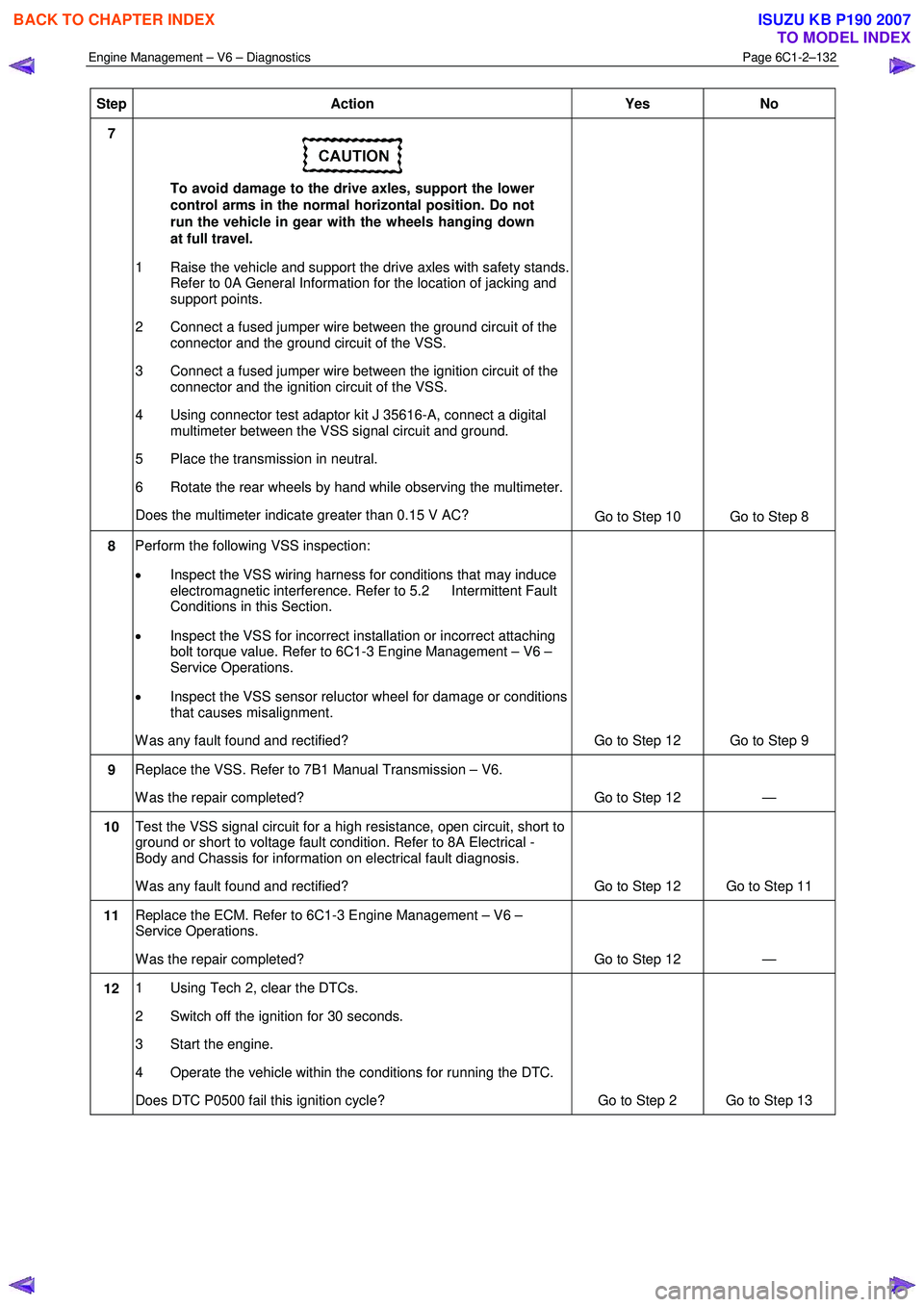
Step Action Yes No
7
To avoid damage to the drive axles, support the lower
control arms in the normal horizontal position. Do not
run the vehicle in gear with the wheels hanging down
at full travel.
1 Raise the vehicle and support the drive axles with safety stands. Refer to 0A General Information for the location of jacking and
support points.
2 Connect a fused jumper wire between the ground circuit of the connector and the ground circuit of the VSS.
3 Connect a fused jumper wire between the ignition circuit of the connector and the ignition circuit of the VSS.
4 Using connector test adaptor kit J 35616-A, connect a digital multimeter between the VSS signal circuit and ground.
5 Place the transmission in neutral.
6 Rotate the rear wheels by hand while observing the multimeter.
Does the multimeter indicate greater than 0.15 V AC? Go to Step 10 Go to Step 8
8 Perform the following VSS inspection:
• Inspect the VSS wiring harness for conditions that may induce
electromagnetic interference. Refer to 5.2 Intermittent Fault
Conditions in this Section.
• Inspect the VSS for incorrect installation or incorrect attaching
bolt torque value. Refer to 6C1-3 Engine Management – V6 –
Service Operations.
• Inspect the VSS sensor reluctor wheel for damage or conditions
that causes misalignment.
W as any fault found and rectified? Go to Step 12 Go to Step 9
9 Replace the VSS. Refer to 7B1 Manual Transmission – V6.
W as the repair completed? Go to Step 12 —
10 Test the VSS signal circuit for a high resistance, open circuit, short to
ground or short to voltage fault condition. Refer to 8A Electrical -
Body and Chassis for information on electrical fault diagnosis.
W as any fault found and rectified? Go to Step 12 Go to Step 11
11 Replace the ECM. Refer to 6C1-3 Engine Management – V6 –
Service Operations.
W as the repair completed? Go to Step 12 —
12 1 Using Tech 2, clear the DTCs.
2 Switch off the ignition for 30 seconds.
3 Start the engine.
4 Operate the vehicle within the conditions for running the DTC.
Does DTC P0500 fail this ignition cycle? Go to Step 2 Go to Step 13
BACK TO CHAPTER INDEX
TO MODEL INDEX
ISUZU KB P190 2007
Page 3461 of 6020
Engine Management – V6 – Diagnostics Page 6C1-2–183
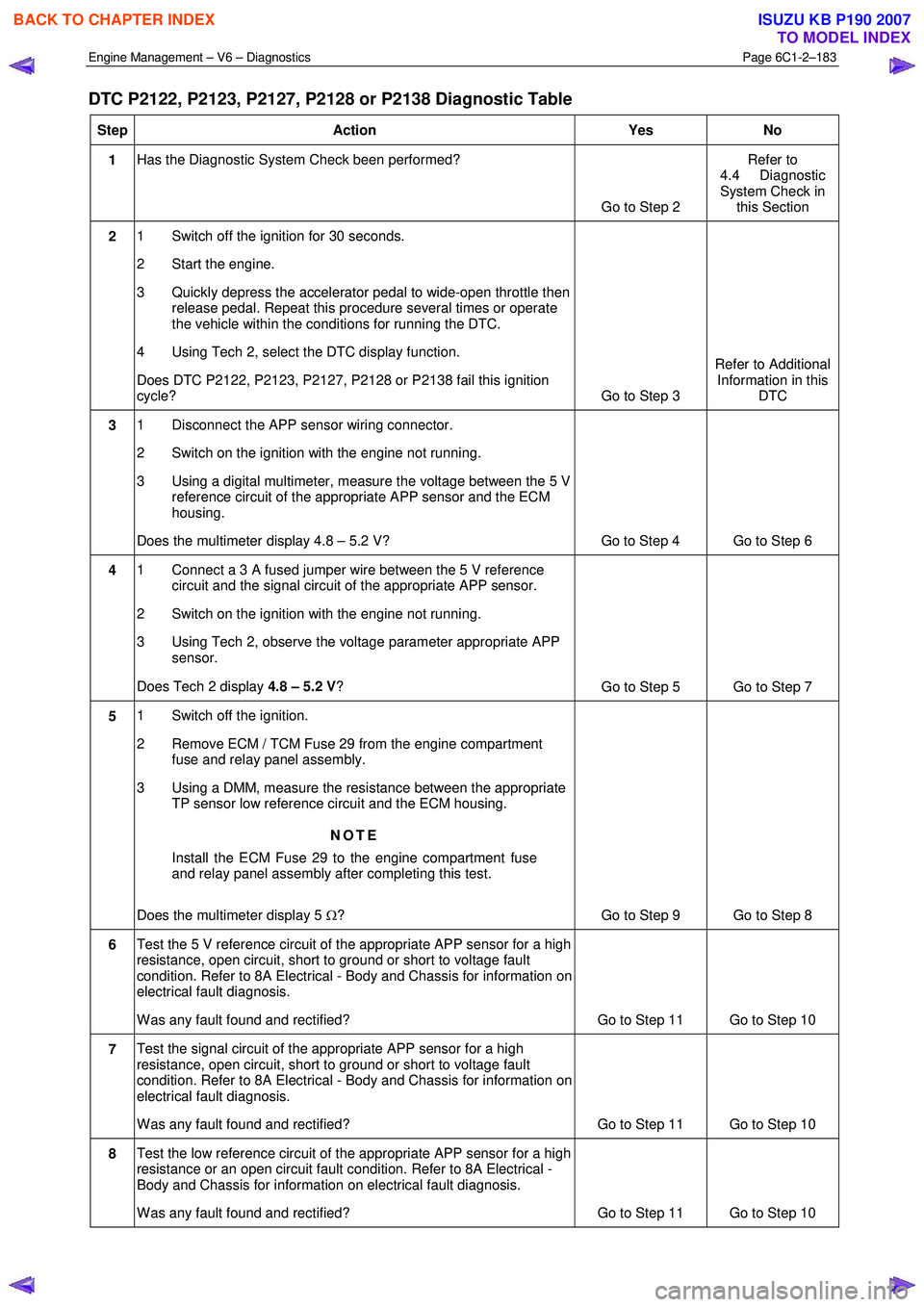
DTC P2122, P2123, P2127, P2128 or P2138 Diagnostic Table
Step Action Yes No
1 Has the Diagnostic System Check been performed?
Go to Step 2 Refer to
4.4 Diagnostic
System Check in this Section
2 1 Switch off the ignition for 30 seconds.
2 Start the engine.
3 Quickly depress the accelerator pedal to wide-open throttle then release pedal. Repeat this procedure several times or operate
the vehicle within the conditions for running the DTC.
4 Using Tech 2, select the DTC display function.
Does DTC P2122, P2123, P2127, P2128 or P2138 fail this ignition
cycle? Go to Step 3 Refer to Additional
Information in this DTC
3 1 Disconnect the APP sensor wiring connector.
2 Switch on the ignition with the engine not running.
3 Using a digital multimeter, measure the voltage between the 5 V reference circuit of the appropriate APP sensor and the ECM
housing.
Does the multimeter display 4.8 – 5.2 V? Go to Step 4 Go to Step 6
4 1 Connect a 3 A fused jumper wire between the 5 V reference
circuit and the signal circuit of the appropriate APP sensor.
2 Switch on the ignition with the engine not running.
3 Using Tech 2, observe the voltage parameter appropriate APP sensor.
Does Tech 2 display 4.8 – 5.2 V ?
Go to Step 5 Go to Step 7
5 1 Switch off the ignition.
2 Remove ECM / TCM Fuse 29 from the engine compartment fuse and relay panel assembly.
3 Using a DMM, measure the resistance between the appropriate TP sensor low reference circuit and the ECM housing.
NOTE
Install the ECM Fuse 29 to the engine compartment fuse
and relay panel assembly after completing this test.
Does the multimeter display 5 Ω? Go to Step 9 Go to Step 8
6 Test the 5 V reference circuit of the appropriate APP sensor for a high
resistance, open circuit, short to ground or short to voltage fault
condition. Refer to 8A Electrical - Body and Chassis for information on
electrical fault diagnosis.
W as any fault found and rectified? Go to Step 11 Go to Step 10
7 Test the signal circuit of the appropriate APP sensor for a high
resistance, open circuit, short to ground or short to voltage fault
condition. Refer to 8A Electrical - Body and Chassis for information on
electrical fault diagnosis.
W as any fault found and rectified? Go to Step 11 Go to Step 10
8 Test the low reference circuit of the appropriate APP sensor for a high
resistance or an open circuit fault condition. Refer to 8A Electrical -
Body and Chassis for information on electrical fault diagnosis.
W as any fault found and rectified? Go to Step 11 Go to Step 10
BACK TO CHAPTER INDEX
TO MODEL INDEX
ISUZU KB P190 2007
Page 3491 of 6020
Engine Management – V6 – Diagnostics Page 6C1-2–213
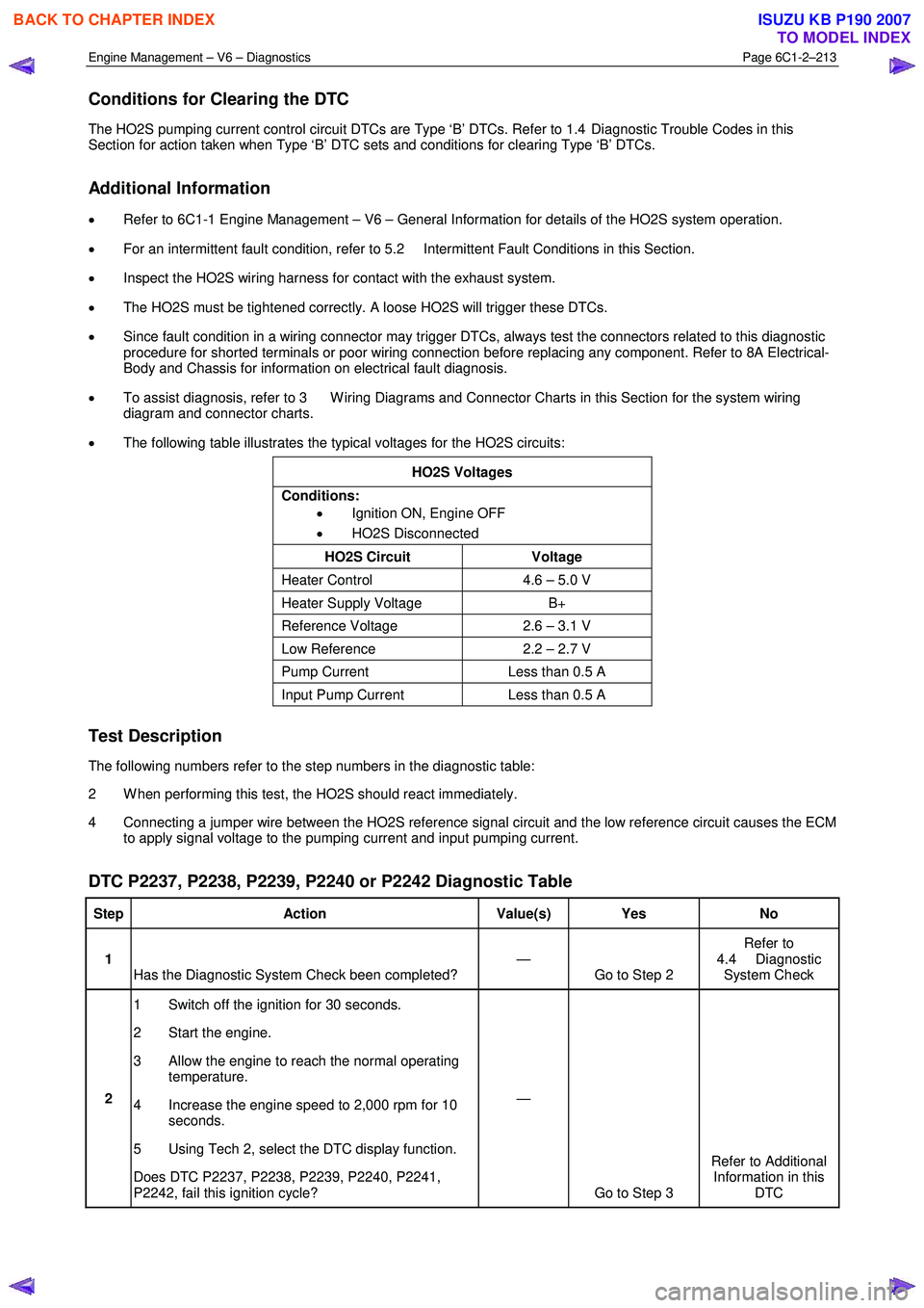
Conditions for Clearing the DTC
The HO2S pumping current control circuit DTCs are Type ‘B’ DTCs. Refer to 1.4 Diagnostic Trouble Codes in this
Section for action taken when Type ‘B’ DTC sets and conditions for clearing Type ‘B’ DTCs.
Additional Information
• Refer to 6C1-1 Engine Management – V6 – General Information for details of the HO2S system operation.
• For an intermittent fault condition, refer to 5.2 Intermittent Fault Conditions in this Section.
• Inspect the HO2S wiring harness for contact with the exhaust system.
• The HO2S must be tightened correctly. A loose HO2S will trigger these DTCs.
• Since fault condition in a wiring connector may trigger DTCs, always test the connectors related to this diagnostic
procedure for shorted terminals or poor wiring connection before replacing any component. Refer to 8A Electrical-
Body and Chassis for information on electrical fault diagnosis.
• To assist diagnosis, refer to 3 W iring Diagrams and Connector Charts in this Section for the system wiring
diagram and connector charts.
• The following table illustrates the typical voltages for the HO2S circuits:
HO2S Voltages
Conditions: • Ignition ON, Engine OFF
• HO2S Disconnected
HO2S Circuit Voltage
Heater Control 4.6 – 5.0 V
Heater Supply Voltage B+
Reference Voltage 2.6 – 3.1 V
Low Reference 2.2 – 2.7 V
Pump Current Less than 0.5 A
Input Pump Current Less than 0.5 A
Test Description
The following numbers refer to the step numbers in the diagnostic table:
2 W hen performing this test, the HO2S should react immediately.
4 Connecting a jumper wire between the HO2S reference signal circuit and the low reference circuit causes the ECM to apply signal voltage to the pumping current and input pumping current.
DTC P2237, P2238, P2239, P2240 or P2242 Diagnostic Table
Step Action Value(s) Yes No
1
Has the Diagnostic System Check been completed? —
Go to Step 2 Refer to
4.4 Diagnostic System Check
2 1 Switch off the ignition for 30 seconds.
2 Start the engine.
3 Allow the engine to reach the normal operating temperature.
4 Increase the engine speed to 2,000 rpm for 10 seconds.
5 Using Tech 2, select the DTC display function.
Does DTC P2237, P2238, P2239, P2240, P2241,
P2242, fail this ignition cycle? —
Go to Step 3 Refer to Additional
Information in this DTC
BACK TO CHAPTER INDEX
TO MODEL INDEX
ISUZU KB P190 2007
Page 3495 of 6020
Engine Management – V6 – Diagnostics Page 6C1-2–217
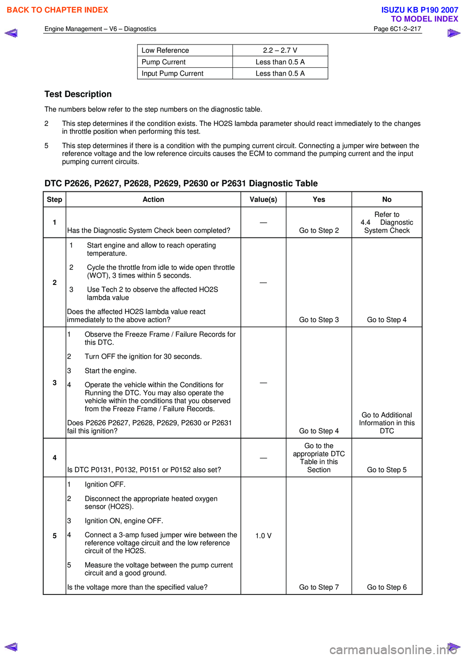
Low Reference 2.2 – 2.7 V
Pump Current Less than 0.5 A
Input Pump Current Less than 0.5 A
Test Description
The numbers below refer to the step numbers on the diagnostic table.
2 This step determines if the condition exists. The HO2S lambda parameter should react immediately to the changes in throttle position when performing this test.
5 This step determines if there is a condition with the pumping current circuit. Connecting a jumper wire between the reference voltage and the low reference circuits causes the ECM to command the pumping current and the input
pumping current circuits.
DTC P2626, P2627, P2628, P2629, P2630 or P2631 Diagnostic Table
Step Action Value(s) Yes No
1
Has the Diagnostic System Check been completed? —
Go to Step 2 Refer to
4.4 Diagnostic System Check
2 1 Start engine and allow to reach operating
temperature.
2 Cycle the throttle from idle to wide open throttle (W OT), 3 times within 5 seconds.
3 Use Tech 2 to observe the affected HO2S lambda value
Does the affected HO2S lambda value react
immediately to the above action? —
Go to Step 3 Go to Step 4
3 1 Observe the Freeze Frame / Failure Records for
this DTC.
2 Turn OFF the ignition for 30 seconds.
3 Start the engine.
4 Operate the vehicle within the Conditions for Running the DTC. You may also operate the
vehicle within the conditions that you observed
from the Freeze Frame / Failure Records.
Does P2626 P2627, P2628, P2629, P2630 or P2631
fail this ignition? —
Go to Step 4 Go to Additional
Information in this DTC
4
Is DTC P0131, P0132, P0151 or P0152 also set? —
Go to the
appropriate DTC Table in this Section Go to Step 5
5 1 Ignition OFF.
2 Disconnect the appropriate heated oxygen sensor (HO2S).
3 Ignition ON, engine OFF.
4 Connect a 3-amp fused jumper wire between the reference voltage circuit and the low reference
circuit of the HO2S.
5 Measure the voltage between the pump current circuit and a good ground.
Is the voltage more than the specified value? 1.0 V
Go to Step 7 Go to Step 6
BACK TO CHAPTER INDEX
TO MODEL INDEX
ISUZU KB P190 2007
Page 3597 of 6020
Charging System – V6 Page 6D1-1-10
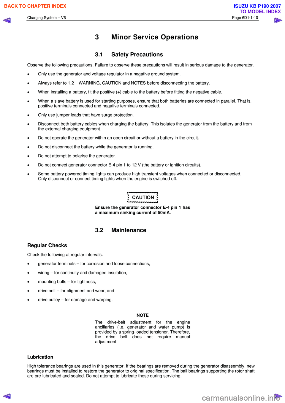
3 Minor Service Operations
3.1 Safety Precautions
Observe the following precautions. Failure to observe these precautions will result in serious damage to the generator.
• Only use the generator and voltage regulator in a negative ground system.
• Always refer to 1.2 W ARNING, CAUTION and NOTES before disconnecting the battery.
• W hen installing a battery, fit the positive (+) cable to the battery before fitting the negative cable.
• W hen a slave battery is used for starting purposes, ensure that both batteries are connected in parallel. That is,
positive terminals connected and negative terminals connected.
• Only use jumper leads that have surge protection.
• Disconnect both battery cables when charging the battery. This isolates the generator from the battery and from
the external charging equipment.
• Do not operate the generator within an open circuit or without a battery in the circuit.
• Do not disconnect the battery while the generator is running.
• Do not attempt to polarise the generator.
• Do not connect generator connector E-4 pin 1 to 12 V (the battery or ignition circuits).
• Some battery powered timing lights can produce high transient voltages when connected or disconnected.
Only disconnect or connect timing lights when the engine is switched off.
Ensure the generator connector E-4 pin 1 has
a maximum sinking current of 50mA.
3.2 Maintenance
Regular Checks
Check the following at regular intervals:
• generator terminals – for corrosion and loose connections,
• wiring – for continuity and damaged insulation,
• mounting bolts – for tightness,
• drive belt – for alignment and wear, and
• drive pulley – for damage and warping.
NOTE
The drive-belt adjustment for the engine
ancillaries (i.e. generator and water pump) is
provided by a spring-loaded tensioner. Therefore,
the drive belt does not require manual
adjustment.
Lubrication
High tolerance bearings are used in this generator. If the bearings are removed during the generator disassembly, new
bearings must be installed to restore the generator to original specification. The ball bearings supporting the rotor shaft
are pre-lubricated and sealed. Do not attempt to lubricate these during servicing.
BACK TO CHAPTER INDEX
TO MODEL INDEX
ISUZU KB P190 2007
Page 3623 of 6020
Starting System – V6 Page 6D1-2–15
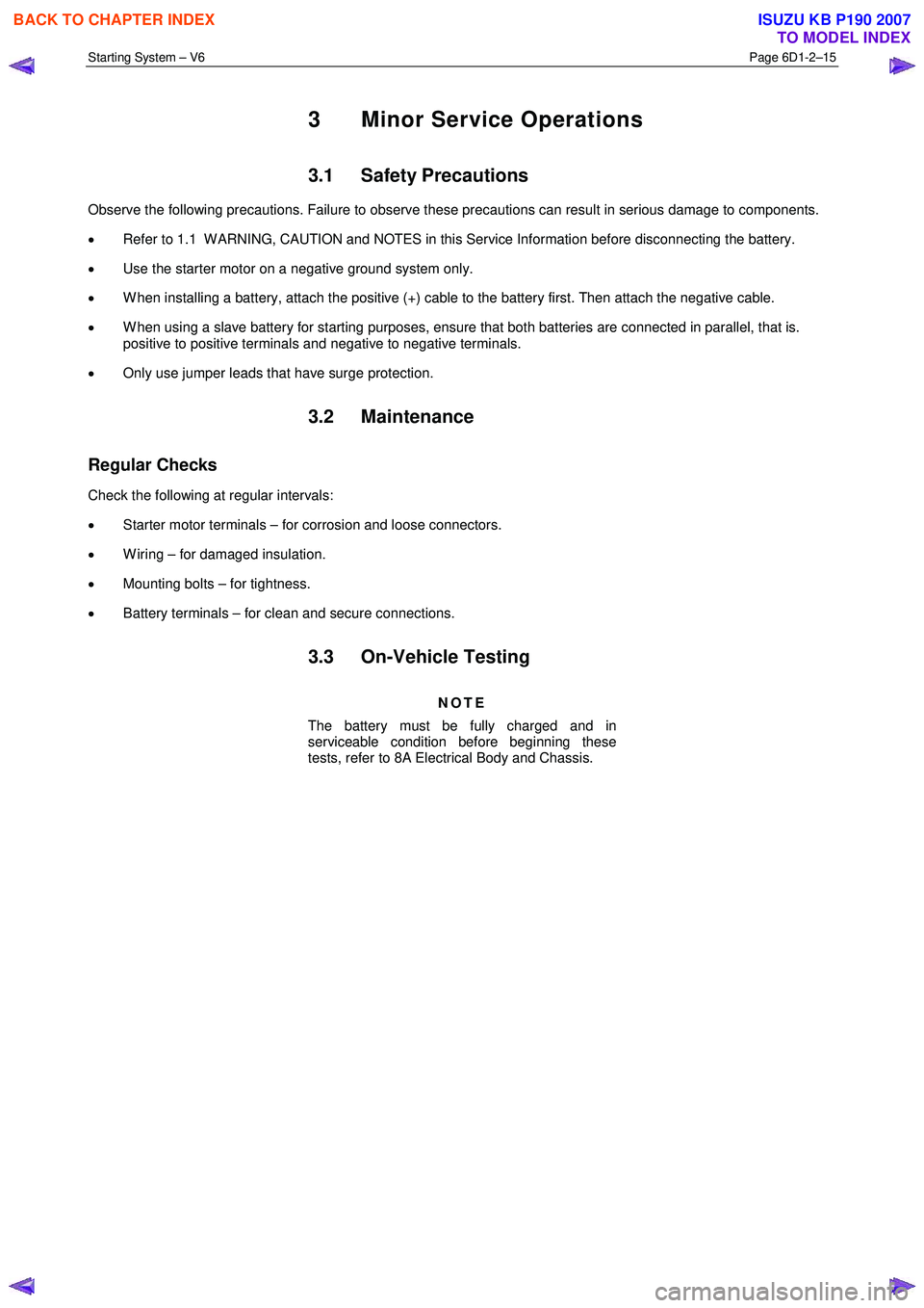
3 Minor Service Operations
3.1 Safety Precautions
Observe the following precautions. Failure to observe these precautions can result in serious damage to components.
• Refer to 1.1 W ARNING, CAUTION and NOTES in this Service Information before disconnecting the battery.
• Use the starter motor on a negative ground system only.
• W hen installing a battery, attach the positive (+) cable to the battery first. Then attach the negative cable.
• W hen using a slave battery for starting purposes, ensure that both batteries are connected in parallel, that is.
positive to positive terminals and negative to negative terminals.
• Only use jumper leads that have surge protection.
3.2 Maintenance
Regular Checks
Check the following at regular intervals:
• Starter motor terminals – for corrosion and loose connectors.
• W iring – for damaged insulation.
• Mounting bolts – for tightness.
• Battery terminals – for clean and secure connections.
3.3 On-Vehicle Testing
NOTE
The battery must be fully charged and in
serviceable condition before beginning these
tests, refer to 8A Electrical Body and Chassis.
BACK TO CHAPTER INDEX
TO MODEL INDEX
ISUZU KB P190 2007