2007 ISUZU KB P190 jump start
[x] Cancel search: jump startPage 617 of 6020

5A-24 BRAKE CONTROL SYSTEM
Computer System Service Precautions
The Anti-lock Brake System and Electronic Brake-force
Distribution interfaces directly with the Electronic
Hydraulic Control Unit (EHCU) which is a control
computer that is similar in some regards to the Engine
Control Module. These modules are designed to
withstand normal current draws associated with vehicle
operation. However, care must be taken to avoid
overloading any of the EHCU circuits. In testing for
opens or shorts, do not ground or apply voltage to any
of the circuits unless instructed to do so by the
appropriate diagnostic procedure. These circuits should
only be tested with a high impedance multimeter
5-8840-0366-0 or special tools as described in this
section. Power should never be removed or applied to
any control module with the ignition in the “ON” position.
Before removing or connecting battery cables, fuses or
connectors, always turn the ignition switch to the “OFF”
position.
General Service Precautions
The following are general precautions which should be
observed when servicing and diagnosing the Anti-lock
Brake System and/or other vehicle systems. Failure to
observe these precautions may result in Anti-lock Brake
System and Electronic Brake-force Distribution
damage.
• If welding work is to be performed on the vehicle using an electric arc welder, the EHCU and valve
block connectors should be disconnected before the
welding operation begins.
• The EHCU and valve block connectors should never be connected or disconnected with the
ignition “ON”.
Note:
• If only rear wheels are rotated using jacks or drum tester, the system will diagnose a speed sensor
malfunction and the “ABS and Brake” warning lamp
will illuminate. But actually no trouble exists. W hen
the DTC is not detected and the ABS and BRAKE
warning lamp is on, “How to erase code” is
performed and an ABS and BRAKE warning lamp
are off.
If the battery has been discharged
The engine may stall if the battery has been completely
discharged and the engine is started via jumper cables.
This is because the Anti-lock Brake System (ABS) and
Electronic Brake-force Distribution (EBD) System
requires a large quantity of electricity. In this case, wait
until the battery is recharged, or set the ABS and EBD
to a non-operative state by removing the fuse for the
ABS. After the battery has been recharged, stop the
engine and install the ABS fuse. Start the engine again,
and confirm that the ABS warning Lamp does not light.
Note on Intermittents
As with virtually any electronic system, it is difficult to
identify an intermittent failure. In such a case duplicating
the system malfunction during a test drive or a good
description of vehicle behavior from the customer may
be helpful in locating a “most likely” failed component or
circuit. The symptom diagnosis chart may also be
useful in isolating the failure. Most intermittent
problems are caused by faulty electrical connections or
wiring. W hen an intermittent failure is encountered,
check suspect circuits for:
• Suspected harness damage.
• Poor mating of connector halves or terminals not fully seated in the connector body (backed out).
• Improperly formed or damaged terminals.
Test Driving ABS Complaint Vehicles
If there has been an abnormality in the lighting pattern
of the “ABS” warning lamp, the fault can be located in
accordance with the “DIAGNOSIS BY “ABS” W ARNING
LAMP ILLUMINATION PATTERN”. Although such
problems can be detected by the driver as a vehicle
symptom, it is still necessary to perform a test drive
following the test procedure mentioned below, in order
to reproduce the symptom for problem diagnosis on a
symptom basis:
1. Start the engine and make sure that the “ABS” W /L
goes OFF. If the W /L remains ON, it means that
the Diagnostic Trouble Code (DTC) is stored.
Therefore, read the code and locate the fault.
Note: The DTC cannot be cleared if the vehicle speed
does not exceed about 10km/h (6mph) at DTC, even
though the repair operation is completed.
2. Start the vehicle and accelerate to about 30 km/h (19 mph) or more.
3. Slowly brake and stop the vehicle completely.
4. Then restart the vehicle and accelerate to about 40 km/h (25 mph) or more.
5. Brake at a time so as to actuate the ABS and stop the vehicle.
6. Be cautious of abnormality during the test. If the W /L is actuated while driving, read the DTC and
locate the fault.
7. If the abnormality is not reproduced by the test, make best efforts to reproduce the situation
reported by the customer.
8. If the abnormality has been detected, repair in accordance with the “SYMPTOM DIAGNOSIS”.
Note:
• Be sure to perform a test drive on a wide, even road
with light traffic.
• If an abnormality is detected, be sure to suspend the test and start trouble diagnosis at once.
BACK TO CHAPTER INDEX
TO MODEL INDEX
ISUZU KB P190 2007
Page 1065 of 6020
Engine Control System (4JH1) 6E-31
Diagnostic Starting Point - Engine Controls
Begin the system diagnosis with Diagnostic System
Check - Engine Controls. The Diagnostic System Check
- Engine Controls will provide the following information:
• The identification of the control modules which
command the system.
• The ability of the control modules to communicate
through the serial data circuit.
• The identification of any stored diagnostic trouble
codes (DTCs) and the their statuses.
The use of the Diagnostic System Check - Engine
Controls will identify the correct procedure fo
r
diagnosing the system and where the procedure is
located.
Important:
Engine Control System Check Sheet must be used to
verify the complaint vehicle, you need to know the
correct (normal) operating behavior of the system and
verify that the customer complaint is a valid failure o
f
the system.
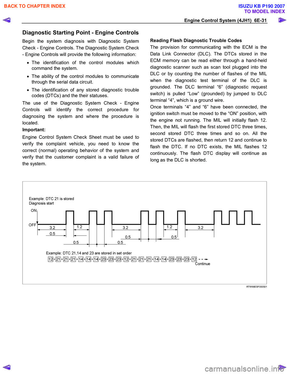
Reading Flash Diagnostic Trouble Codes
The provision for communicating with the ECM is the
Data Link Connector (DLC). The DTCs stored in the
ECM memory can be read either through a hand-held
diagnostic scanner such as scan tool plugged into the
DLC or by counting the number of flashes of the MIL
when the diagnostic test terminal of the DLC is
grounded. The DLC terminal “6” (diagnostic request
switch) is pulled “Low” (grounded) by jumped to DLC
terminal “4”, which is a ground wire.
Once terminals “4” and “6” have been connected, the
ignition switch must be moved to the “ON” position, with
the engine not running. The MIL will initially flash 12.
Then, the MIL will flash the first stored DTC three times,
second stored DTC three times and so on. All the
stored DTCs are flashed, then return 12 and continue to
flash the DTC. If no DTC exists, the MIL flashes 12
continuously. The flash DTC display will continue as
long as the DLC is shorted.
RTW 66ESF000501
BACK TO CHAPTER INDEX
TO MODEL INDEX
ISUZU KB P190 2007
Page 1092 of 6020
6E-58 Engine Control System (4JH1)
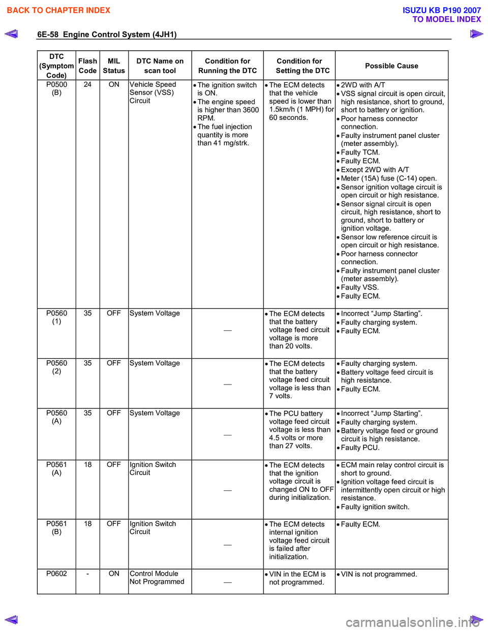
DTC
(Symptom Code) Flash
Code MIL
Status DTC Name on
scan tool Condition for
Running the DTC Condition for
Setting the DTC Possible Cause
P0500
(B) 24 ON Vehicle Speed
Sensor (VSS)
Circuit
•
The ignition switch
is ON.
• The engine speed
is higher than 3600
RPM.
• The fuel injection
quantity is more
than 41 mg/strk.
•
The ECM detects
that the vehicle
speed is lower than
1.5km/h (1 MPH) for
60 seconds.
•
2W D with A/T
• VSS signal circuit is open circuit,
high resistance, short to ground,
short to battery or ignition.
• Poor harness connector
connection.
• Faulty instrument panel cluster
(meter assembly).
• Faulty TCM.
• Faulty ECM.
• Except 2W D with A/T
• Meter (15A) fuse (C-14) open.
• Sensor ignition voltage circuit is
open circuit or high resistance.
• Sensor signal circuit is open
circuit, high resistance, short to
ground, short to battery or
ignition voltage.
• Sensor low reference circuit is
open circuit or high resistance.
• Poor harness connector
connection.
• Faulty instrument panel cluster
(meter assembly).
• Faulty VSS.
• Faulty ECM.
P0560 (1) 35 OFF System Voltage
•
The ECM detects
that the battery
voltage feed circuit
voltage is more
than 20 volts.
•
Incorrect “Jump Starting”.
• Faulty charging system.
• Faulty ECM.
P0560 (2) 35 OFF System Voltage
•
The ECM detects
that the battery
voltage feed circuit
voltage is less than
7 volts.
•
Faulty charging system.
• Battery voltage feed circuit is
high resistance.
• Faulty ECM.
P0560 (A) 35 OFF System Voltage
•
The PCU battery
voltage feed circuit
voltage is less than
4.5 volts or more
than 27 volts.
•
Incorrect “Jump Starting”.
• Faulty charging system.
• Battery voltage feed or ground
circuit is high resistance.
• Faulty PCU.
P0561 (A) 18 OFF Ignition Switch
Circuit
•
The ECM detects
that the ignition
voltage circuit is
changed ON to OFF
during initialization.
•
ECM main relay control circuit is
short to ground.
• Ignition voltage feed circuit is
intermittently open circuit or high
resistance.
• Faulty ignition switch.
P0561 (B) 18 OFF Ignition Switch
Circuit
•
The ECM detects
internal ignition
voltage feed circuit
is failed after
initialization.
•
Faulty ECM.
P0602 - ON Control Module
Not Programmed
•
VIN in the ECM is
not programmed. •
VIN is not programmed.
BACK TO CHAPTER INDEX
TO MODEL INDEX
ISUZU KB P190 2007
Page 1105 of 6020
Engine Control System (4JH1) 6E-71
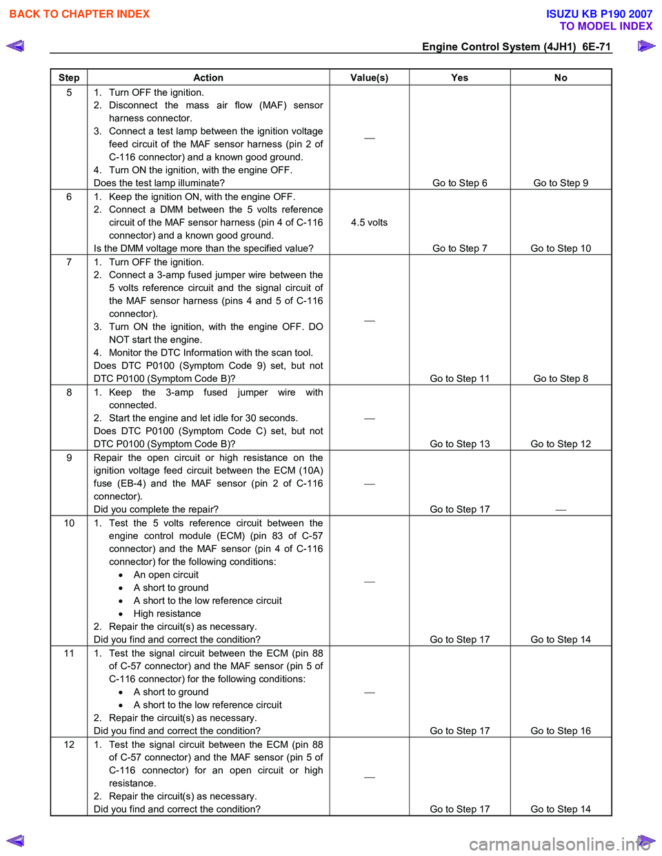
Step Action Value(s) Yes No
5 1. Turn OFF the ignition.
2. Disconnect the mass air flow (MAF) sensor harness connector.
3. Connect a test lamp between the ignition voltage feed circuit of the MAF sensor harness (pin 2 of
C-116 connector) and a known good ground.
4. Turn ON the ignition, with the engine OFF.
Does the test lamp illuminate?
Go to Step 6 Go to Step 9
6 1. Keep the ignition ON, with the engine OFF. 2. Connect a DMM between the 5 volts reference circuit of the MAF sensor harness (pin 4 of C-116
connector) and a known good ground.
Is the DMM voltage more than the specified value? 4.5 volts
Go to Step 7 Go to Step 10
7 1. Turn OFF the ignition. 2. Connect a 3-amp fused jumper wire between the 5 volts reference circuit and the signal circuit of
the MAF sensor harness (pins 4 and 5 of C-116
connector).
3. Turn ON the ignition, with the engine OFF. DO NOT start the engine.
4. Monitor the DTC Information with the scan tool.
Does DTC P0100 (Symptom Code 9) set, but not
DTC P0100 (Symptom Code B)?
Go to Step 11 Go to Step 8
8 1. Keep the 3-amp fused jumper wire with connected.
2. Start the engine and let idle for 30 seconds.
Does DTC P0100 (Symptom Code C) set, but not
DTC P0100 (Symptom Code B)?
Go to Step 13 Go to Step 12
9 Repair the open circuit or high resistance on the ignition voltage feed circuit between the ECM (10A)
fuse (EB-4) and the MAF sensor (pin 2 of C-116
connector).
Did you complete the repair?
Go to Step 17
10 1. Test the 5 volts reference circuit between the
engine control module (ECM) (pin 83 of C-57
connector) and the MAF sensor (pin 4 of C-116
connector) for the following conditions: • An open circuit
• A short to ground
• A short to the low reference circuit
• High resistance
2. Repair the circuit(s) as necessary.
Did you find and correct the condition?
Go to Step 17 Go to Step 14
11 1. Test the signal circuit between the ECM (pin 88 of C-57 connector) and the MAF sensor (pin 5 of
C-116 connector) for the following conditions: • A short to ground
• A short to the low reference circuit
2. Repair the circuit(s) as necessary.
Did you find and correct the condition?
Go to Step 17 Go to Step 16
12 1. Test the signal circuit between the ECM (pin 88 of C-57 connector) and the MAF sensor (pin 5 of
C-116 connector) for an open circuit or high
resistance.
2. Repair the circuit(s) as necessary.
Did you find and correct the condition?
Go to Step 17 Go to Step 14
BACK TO CHAPTER INDEX
TO MODEL INDEX
ISUZU KB P190 2007
Page 1200 of 6020
6E-166 Engine Control System (4JH1)
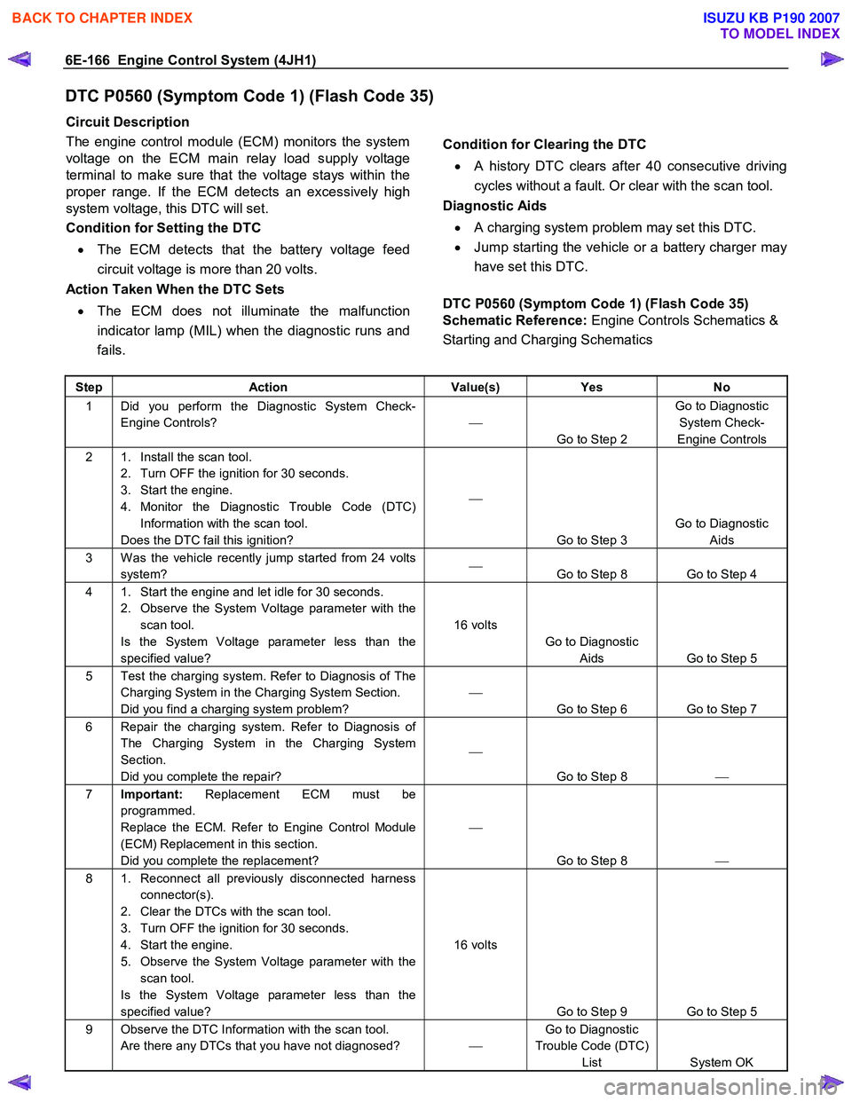
DTC P0560 (Symptom Code 1) (Flash Code 35)
Circuit Description
The engine control module (ECM) monitors the system
voltage on the ECM main relay load supply voltage
terminal to make sure that the voltage stays within the
proper range. If the ECM detects an excessively high
system voltage, this DTC will set.
Condition for Setting the DTC
• The ECM detects that the battery voltage feed
circuit voltage is more than 20 volts.
Action Taken When the DTC Sets
• The ECM does not illuminate the malfunction
indicator lamp (MIL) when the diagnostic runs and
fails.
Condition for Clearing the DTC • A history DTC clears after 40 consecutive driving
cycles without a fault. Or clear with the scan tool.
Diagnostic Aids
• A charging system problem may set this DTC.
• Jump starting the vehicle or a battery charger may
have set this DTC.
DTC P0560 (Symptom Code 1) (Flash Code 35)
Schematic Reference: Engine Controls Schematics &
Starting and Charging Schematics
Step Action Value(s) Yes No
1 Did you perform the Diagnostic System Check-
Engine Controls?
Go to Step 2 Go to Diagnostic
System Check-
Engine Controls
2 1. Install the scan tool. 2. Turn OFF the ignition for 30 seconds.
3. Start the engine.
4. Monitor the Diagnostic Trouble Code (DTC) Information with the scan tool.
Does the DTC fail this ignition?
Go to Step 3 Go to Diagnostic
Aids
3 W as the vehicle recently jump started from 24 volts system?
Go to Step 8 Go to Step 4
4 1. Start the engine and let idle for 30 seconds.
2. Observe the System Voltage parameter with the scan tool.
Is the System Voltage parameter less than the
specified value? 16 volts
Go to Diagnostic Aids Go to Step 5
5 Test the charging system. Refer to Diagnosis of The Charging System in the Charging System Section.
Did you find a charging system problem?
Go to Step 6 Go to Step 7
6 Repair the charging system. Refer to Diagnosis of The Charging System in the Charging System
Section.
Did you complete the repair?
Go to Step 8
7 Important: Replacement ECM must be
programmed.
Replace the ECM. Refer to Engine Control Module
(ECM) Replacement in this section.
Did you complete the replacement?
Go to Step 8
8 1. Reconnect all previously disconnected harness
connector(s).
2. Clear the DTCs with the scan tool.
3. Turn OFF the ignition for 30 seconds.
4. Start the engine.
5. Observe the System Voltage parameter with the scan tool.
Is the System Voltage parameter less than the
specified value? 16 volts
Go to Step 9 Go to Step 5
9 Observe the DTC Information with the scan tool. Are there any DTCs that you have not diagnosed? Go to Diagnostic
Trouble Code (DTC) List System OK
BACK TO CHAPTER INDEX
TO MODEL INDEX
ISUZU KB P190 2007
Page 1203 of 6020
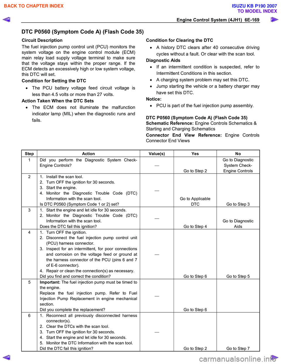
Engine Control System (4JH1) 6E-169
DTC P0560 (Symptom Code A) (Flash Code 35)
Circuit Description
The fuel injection pump control unit (PCU) monitors the
system voltage on the engine control module (ECM)
main relay load supply voltage terminal to make sure
that the voltage stays within the proper range. If the
ECM detects an excessively high or low system voltage,
this DTC will set.
Condition for Setting the DTC
• The PCU battery voltage feed circuit voltage is
less than 4.5 volts or more than 27 volts.
Action Taken When the DTC Sets
• The ECM does not illuminate the malfunction
indicator lamp (MIL) when the diagnostic runs and
fails.
Condition for Clearing the DTC
• A history DTC clears after 40 consecutive driving
cycles without a fault. Or clear with the scan tool.
Diagnostic Aids
• If an intermittent condition is suspected, refer to
Intermittent Conditions in this section.
• A charging system problem may set this DTC.
• Jump starting the vehicle or a battery charger may
have set this DTC.
Notice:
• PCU is part of the fuel injection pump assembly.
DTC P0560 (Symptom Code A) (Flash Code 35)
Schematic Reference: Engine Controls Schematics &
Starting and Charging Schematics
Connector End View Reference: Engine Controls
Connector End Views
Step Action Value(s) Yes No
1 Did you perform the Diagnostic System Check-
Engine Controls?
Go to Step 2 Go to Diagnostic
System Check-
Engine Controls
2 1. Install the scan tool. 2. Turn OFF the ignition for 30 seconds.
3. Start the engine.
4. Monitor the Diagnostic Trouble Code (DTC) Information with the scan tool.
Is DTC P0560 (Symptom Code 1 or 2) set?
Go to Applicable DTC Go to Step 3
3 1. Start the engine and let idle for 30 seconds. 2. Monitor the Diagnostic Trouble Code (DTC) Information with the scan tool.
Does the DTC fail this ignition?
Go to Step 4 Go to Diagnostic
Aids
4 1. Turn OFF the ignition. 2. Disconnect the fuel injection pump control unit (PCU) harness connector.
3. Inspect for an intermittent, for poor connections and corrosion on the voltage feed or ground at
the harness connector of the PCU (pins 6 and 7
of E-6 connector).
4. Repair or clean the connection(s) as necessary.
Did you find and correct the condition?
Go to Step 6 Go to Step 5
5 Important: The fuel injection pump must be timed to
the engine.
Replace the fuel injection pump. Refer to Fuel
Injection Pump Replacement in engine mechanical
section.
Did you complete the replacement?
Go to Step 6
6 1. Reconnect all previously disconnected harness connector(s).
2. Clear the DTCs with the scan tool.
3. Turn OFF the ignition for 30 seconds.
4. Start the engine and let idle for 30 seconds.
5. Monitor the DTC Information with the scan tool.
Did the DTC fail this ignition?
Go to Step 2 Go to Step 7
BACK TO CHAPTER INDEX
TO MODEL INDEX
ISUZU KB P190 2007
Page 1277 of 6020
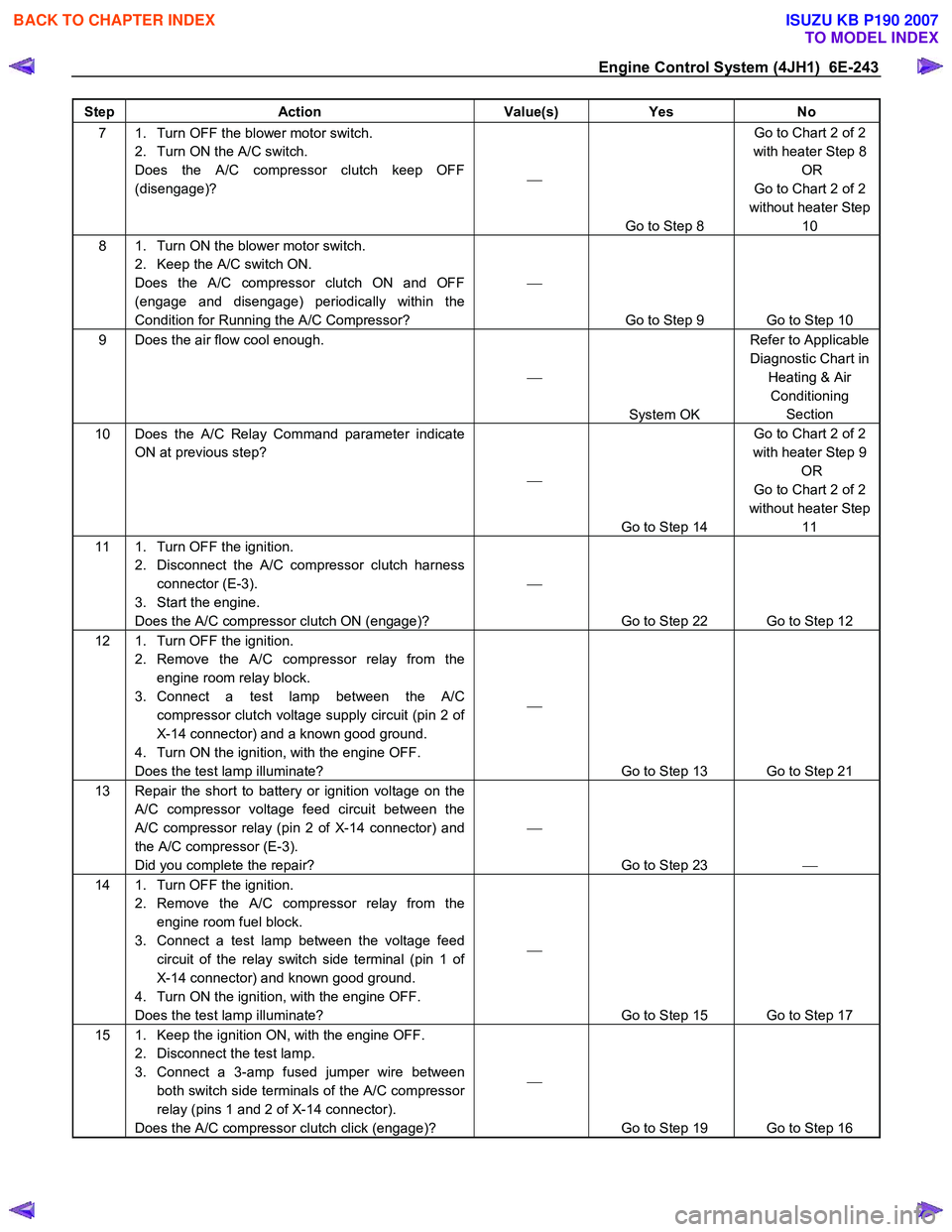
Engine Control System (4JH1) 6E-243
Step Action Value(s) Yes No
7 1. Turn OFF the blower motor switch.
2. Turn ON the A/C switch.
Does the A/C compressor clutch keep OFF
(disengage)?
Go to Step 8 Go to Chart 2 of 2
with heater Step 8 OR
Go to Chart 2 of 2
without heater Step 10
8 1. Turn ON the blower motor switch. 2. Keep the A/C switch ON.
Does the A/C compressor clutch ON and OFF
(engage and disengage) periodically within the
Condition for Running the A/C Compressor?
Go to Step 9 Go to Step 10
9 Does the air flow cool enough.
System OK Refer to Applicable
Diagnostic Chart in Heating & Air Conditioning Section
10 Does the A/C Relay Command parameter indicate ON at previous step?
Go to Step 14 Go to Chart 2 of 2
with heater Step 9 OR
Go to Chart 2 of 2
without heater Step 11
11 1. Turn OFF the ignition. 2. Disconnect the A/C compressor clutch harness connector (E-3).
3. Start the engine.
Does the A/C compressor clutch ON (engage)?
Go to Step 22 Go to Step 12
12 1. Turn OFF the ignition. 2. Remove the A/C compressor relay from the engine room relay block.
3. Connect a test lamp between the A/C compressor clutch voltage supply circuit (pin 2 of
X-14 connector) and a known good ground.
4. Turn ON the ignition, with the engine OFF.
Does the test lamp illuminate?
Go to Step 13 Go to Step 21
13 Repair the short to battery or ignition voltage on the A/C compressor voltage feed circuit between the
A/C compressor relay (pin 2 of X-14 connector) and
the A/C compressor (E-3).
Did you complete the repair?
Go to Step 23
14 1. Turn OFF the ignition.
2. Remove the A/C compressor relay from the engine room fuel block.
3. Connect a test lamp between the voltage feed circuit of the relay switch side terminal (pin 1 of
X-14 connector) and known good ground.
4. Turn ON the ignition, with the engine OFF.
Does the test lamp illuminate?
Go to Step 15 Go to Step 17
15 1. Keep the ignition ON, with the engine OFF. 2. Disconnect the test lamp.
3. Connect a 3-amp fused jumper wire between both switch side terminals of the A/C compressor
relay (pins 1 and 2 of X-14 connector).
Does the A/C compressor clutch click (engage)?
Go to Step 19 Go to Step 16
BACK TO CHAPTER INDEX
TO MODEL INDEX
ISUZU KB P190 2007
Page 1280 of 6020
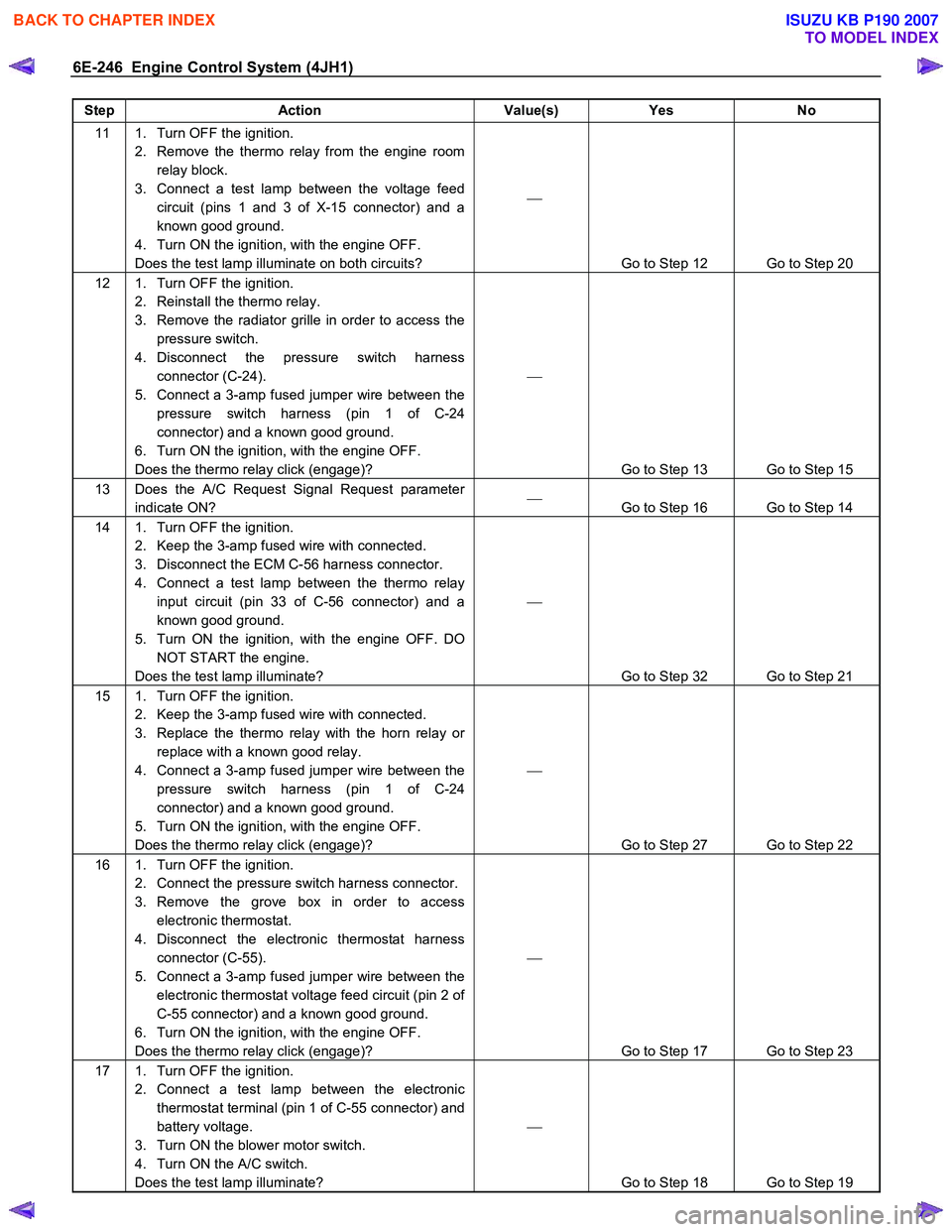
6E-246 Engine Control System (4JH1)
Step Action Value(s) Yes No
11 1. Turn OFF the ignition.
2. Remove the thermo relay from the engine room relay block.
3. Connect a test lamp between the voltage feed circuit (pins 1 and 3 of X-15 connector) and a
known good ground.
4. Turn ON the ignition, with the engine OFF.
Does the test lamp illuminate on both circuits?
Go to Step 12 Go to Step 20
12 1. Turn OFF the ignition. 2. Reinstall the thermo relay.
3. Remove the radiator grille in order to access the pressure switch.
4. Disconnect the pressure switch harness connector (C-24).
5. Connect a 3-amp fused jumper wire between the pressure switch harness (pin 1 of C-24
connector) and a known good ground.
6. Turn ON the ignition, with the engine OFF.
Does the thermo relay click (engage)?
Go to Step 13 Go to Step 15
13 Does the A/C Request Signal Request parameter indicate ON?
Go to Step 16 Go to Step 14
14 1. Turn OFF the ignition.
2. Keep the 3-amp fused wire with connected.
3. Disconnect the ECM C-56 harness connector.
4. Connect a test lamp between the thermo relay input circuit (pin 33 of C-56 connector) and a
known good ground.
5. Turn ON the ignition, with the engine OFF. DO NOT START the engine.
Does the test lamp illuminate?
Go to Step 32 Go to Step 21
15 1. Turn OFF the ignition. 2. Keep the 3-amp fused wire with connected.
3. Replace the thermo relay with the horn relay or replace with a known good relay.
4. Connect a 3-amp fused jumper wire between the pressure switch harness (pin 1 of C-24
connector) and a known good ground.
5. Turn ON the ignition, with the engine OFF.
Does the thermo relay click (engage)?
Go to Step 27 Go to Step 22
16 1. Turn OFF the ignition. 2. Connect the pressure switch harness connector.
3. Remove the grove box in order to access electronic thermostat.
4. Disconnect the electronic thermostat harness connector (C-55).
5. Connect a 3-amp fused jumper wire between the electronic thermostat voltage feed circuit (pin 2 of
C-55 connector) and a known good ground.
6. Turn ON the ignition, with the engine OFF.
Does the thermo relay click (engage)?
Go to Step 17 Go to Step 23
17 1. Turn OFF the ignition. 2. Connect a test lamp between the electronic thermostat terminal (pin 1 of C-55 connector) and
battery voltage.
3. Turn ON the blower motor switch.
4. Turn ON the A/C switch.
Does the test lamp illuminate?
Go to Step 18 Go to Step 19
BACK TO CHAPTER INDEX
TO MODEL INDEX
ISUZU KB P190 2007