2007 ISUZU KB P190 jump start
[x] Cancel search: jump startPage 4020 of 6020
7A2-54 TRANSMISSION CONTROL SYSTEM (AW30–40LE)
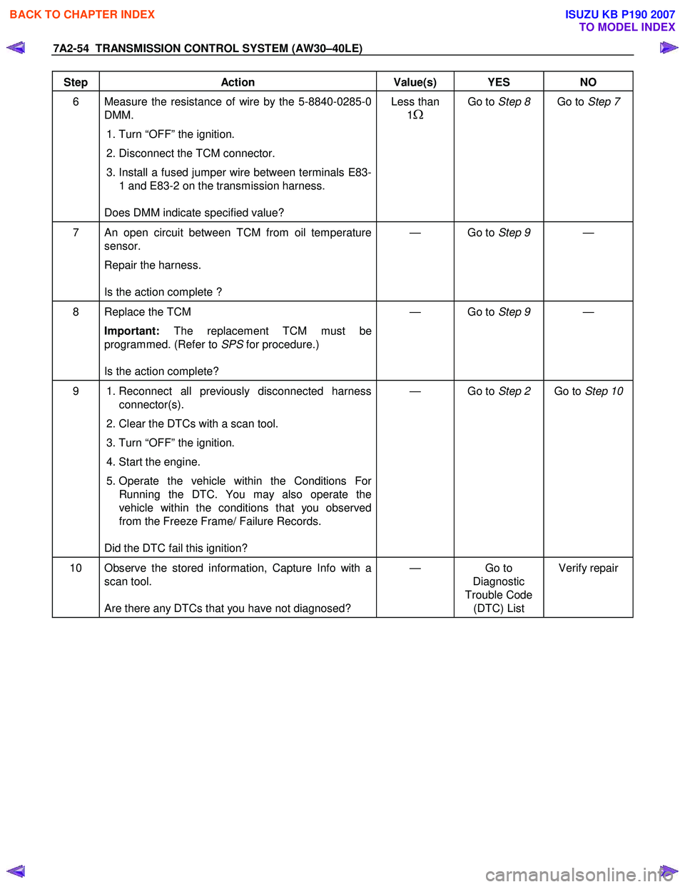
Step Action Value(s) YES NO
6 Measure the resistance of wire by the 5-8840-0285-0
DMM.
1. Turn “OFF” the ignition.
2. Disconnect the TCM connector.
3. Install a fused jumper wire between terminals E83-
1 and E83-2 on the transmission harness.
Does DMM indicate specified value? Less than
1
Ω
Go to Step 8 Go to Step 7
7 An open circuit between TCM from oil temperature
sensor.
Repair the harness.
Is the action complete ? — Go to
Step 9 —
8 Replace the TCM
Important: The replacement TCM must be
programmed. (Refer to SPS for procedure.)
Is the action complete? — Go to
Step 9 —
9 1. Reconnect all previously disconnected harness
connector(s).
2. Clear the DTCs with a scan tool.
3. Turn “OFF” the ignition.
4. Start the engine.
5. Operate the vehicle within the Conditions For Running the DTC. You may also operate the
vehicle within the conditions that you observed
from the Freeze Frame/ Failure Records.
Did the DTC fail this ignition? — Go to
Step 2 Go to Step 10
10 Observe the stored information, Capture Info with a
scan tool.
Are there any DTCs that you have not diagnosed? — Go
to
Diagnostic
Trouble Code (DTC) List Verify repair
BACK TO CHAPTER INDEX
TO MODEL INDEX
ISUZU KB P190 2007
Page 4305 of 6020
TRANSMISSION CONTROL SYSTEM (JR405E) 7A2-21
Diagnostic Information and Procedures
Diagnostic Starting Point - Transmission Controls
Begin the system diagnosis with Diagnostic System
Check - Transmission Controls. The Diagnostic System
Check - Transmission Controls will provide the
following information:
• The identification of the control modules which command the system.
• The ability of the control modules to communicate through the serial data circuit.
• The identification of any stored diagnostic trouble codes (DTCs) and the their statuses.
The use of the Diagnostic System Check -
Transmission Controls will identify the correct
procedure for diagnosing the system and where the
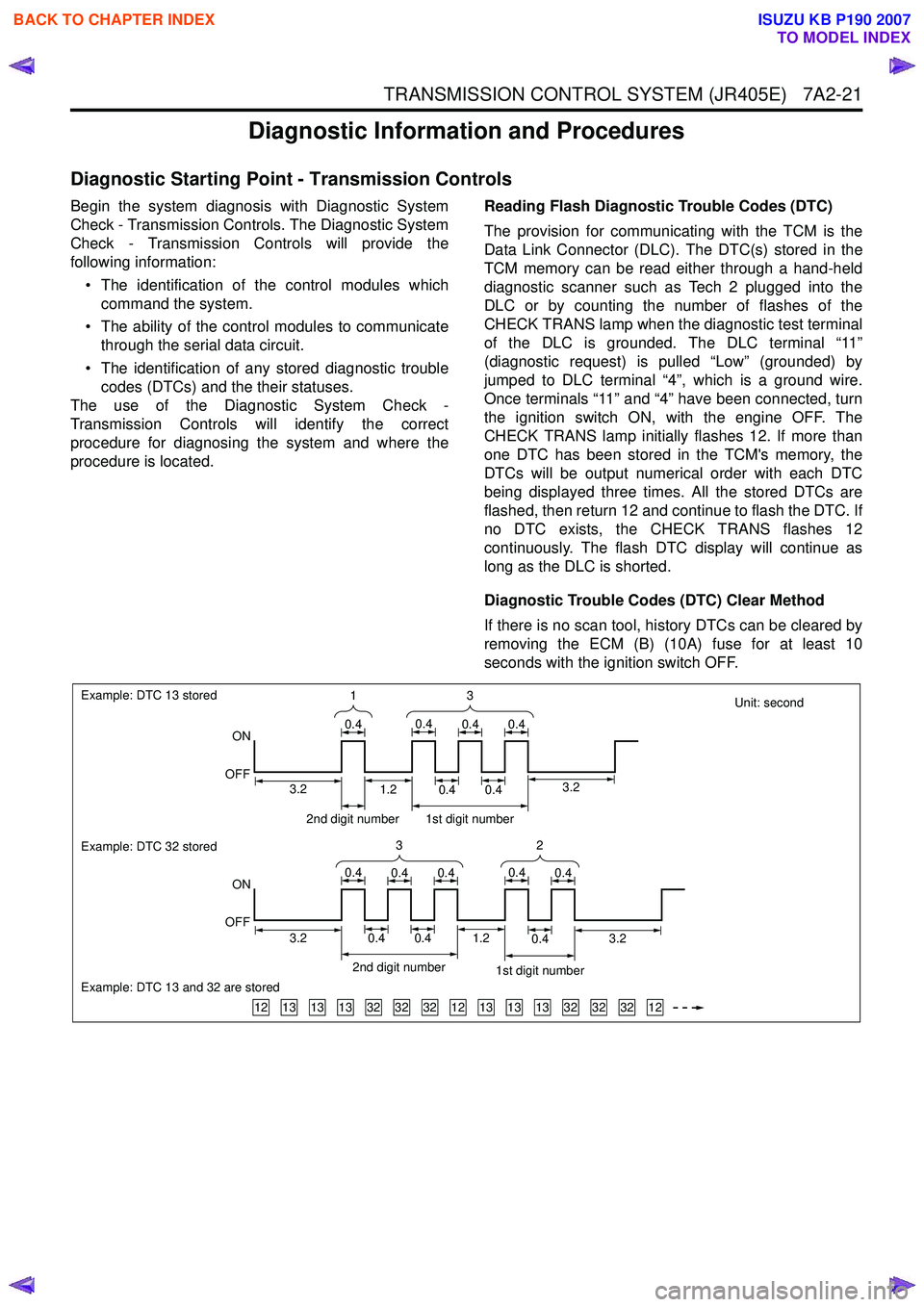
procedure is located. Reading Flash Diagnostic Trouble Codes (DTC)
The provision for communicating with the TCM is the
Data Link Connector (DLC). The DTC(s) stored in the
TCM memory can be read either through a hand-held
diagnostic scanner such as Tech 2 plugged into the
DLC or by counting the number of flashes of the
CHECK TRANS lamp when the diagnostic test terminal
of the DLC is grounded. The DLC terminal “11”
(diagnostic request) is pulled “Low” (grounded) by
jumped to DLC terminal “4”, which is a ground wire.
Once terminals “11” and “4” have been connected, turn
the ignition switch ON, with the engine OFF. The
CHECK TRANS lamp initially flashes 12. If more than
one DTC has been stored in the TCM's memory, the
DTCs will be output numerical order with each DTC
being displayed three times. All the stored DTCs are
flashed, then return 12 and continue to flash the DTC. If
no DTC exists, the CHECK TRANS flashes 12
continuously. The flash DTC display will continue as
long as the DLC is shorted.
Diagnostic Trouble Codes (DTC) Clear Method
If there is no scan tool, history DTCs can be cleared by
removing the ECM (B) (10A) fuse for at least 10
seconds with the ignition switch OFF.
Unit: second
131313323232121313133232321212
Example: DTC 13 stored
ON
OFF
Example: DTC 32 stored
Example: DTC 13 and 32 are stored
ON
OFF 3
1
0.40.40.40.4
32
0.40.40.40.40.4
2nd digit number1st digit number
3.23.20.40.40.41.2
2nd digit number 1st digit number
0.40.41.23.23.2
BACK TO CHAPTER INDEX
TO MODEL INDEX
ISUZU KB P190 2007
Page 4334 of 6020

7A2-50 TRANSMISSION CONTROL SYSTEM (JR405E)
DTC P0727 (Flash Code 13)
Circuit Description
The engine speed signal to the TCM is sent from the
engine control module (ECM) via a signal circuit based
on inputs from the crankshaft position (CKP) sensor
and camshaft position (CMP) sensor. If the TCM
detects no engine speed signal from the ECM during
the vehicle running, this DTC will set.
Condition for Running the DTC • The ignition switch is ON.
• The vehicle speed is more than 40 km/h (24 MPH).
Condition for Setting the DTC • The TCM detects that the engine speed signal pulses from the ECM are not being received for 2
seconds. Action Taken When the DTC Sets
• The TCM blinks the Check Trans lamp when the diagnostic runs and fails.
• The TCM inhibits lock up control.
Condition for Clearing the DTC • The TCM turns OFF the Check Trans lamp when the diagnostic runs and does not fail.
• A current DTC clears when the diagnostic runs and does not fail.
Diagnostic Aids • If an intermittent condition is suspected, refer to Intermittent Conditions in this section.
Schematic Reference: Transmission Controls
Schematics
Connector End View Reference: Transmission
Controls Connector End Views or TCM Connector End
Views
Circuit/ System Testing DTC P0727
Step Action Value(s)Yes No
1 Did you perform the Diagnostic System Check -
Transmission Controls? —
Go to Step 2 Go to Diagnostic
System Check -
Transmission Controls
2 1. Install a scan tool.
2. Turn OFF the ignition for 30 seconds.
3. Start the engine. If the engine does not start, crank over the engine for 10 seconds.
4. Monitor the ENGINE DTC Information with a scan tool.
Is DTC P0335, P0336, P0340 or P0341 set? —
Go to Applicable DTC in engine
control section Go to Step 3
3 Observe the Engine Speed parameter in the
transmission data display with a scan tool.
Does the scan tool indicate correct engine speed? —
Go to Diagnostic
Aids Go to Step 4
4 1. Turn OFF the ignition.
2. Disconnect the engine control module (ECM) harness connector.
3. Turn ON the ignition, with the engine OFF.
4. Intermittently jump the signal circuit (pin 33 of C-58) with a test lamp that is connected to a
known good ground while observing the
Engine Speed parameter with a scan tool.
Does the scan tool indicate any engine speed when
the circuit is intermittently pulled to ground? —
Go to Step 7 Go to Step 5
BACK TO CHAPTER INDEX
TO MODEL INDEX
ISUZU KB P190 2007
Page 4957 of 6020
ELECTRICAL-BODY AND CHASSIS 8A-19
Battery-1
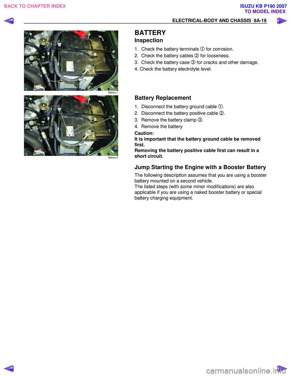
BATTERY
Inspection
1. Check the battery terminals 1 for corrosion.
2. Check the battery cables
2 for looseness.
3. Check the battery case
3 for cracks and other damage.
4. Check the battery electrolyte level.
Battery-2
Battery Replacement
1. Disconnect the battery ground cable 1.
2. Disconnect the battery positive cable
2.
3. Remove the battery clamp
3.
4. Remove the battery
Caution:
It is important that the battery ground cable be removed
first.
Removing the battery positive cable first can result in a
short circuit.
Jump Starting the Engine with a Booster Battery
The following description assumes that you are using a booster
battery mounted on a second vehicle.
The listed steps (with some minor modifications) are also
applicable if you are using a naked booster battery or special
battery charging equipment.
BACK TO CHAPTER INDEX TO MODEL INDEXISUZU KB P190 2007
Page 4958 of 6020
8A-20 ELECTRICAL-BODY AND CHASSIS
Caution:
Never push or tow the vehicle in an attempt to start it.
Extensive damage to the emission system and other
vehicle parts will result.
(Only catalytic converter vehicle)
Treat both the discharged battery and the booster battery
with great care when using jumper cables.
Carefully follow the procedure outlined below.
Always be aware of the dangers of sparking.
Failure to follow the following procedure can result in:
a. Serious personal injury, specially to your eyes.
b. Extensive property damage from a battery explosion, battery acid discharge, or electrical file.
c. Extensive damage to the electronic components o
f
both vehicles.
Do not use a 24 volt booster battery.
Serious damage to the vehicle's electrical system and
electronic components will result.
Jump Starting Procedure
1. Set the parking brake on both vehicles.
2. If one or both vehicles is equipped with a manual transmission, place the gear shift in the "NEUTRAL"
position.
3. Turn off the ignition on both vehicles.
4. Turn off all vehicle lights and accessories.
5 Be sure that the two vehicles are not touching.
Attach the end of one jumper cable to the booster battery
positive terminal.
6
Attach the other end of the same cable to the discharged
battery positive terminal.
7. Once again, check that the booster battery has a 12 volt rating.
8.
Attach one end of the remaining booster cable to the
booster battery negative terminal.
9.
Attach the other end of the booster cable to a solid ground
(such as the air conditioner compressor mounting bracket
or the alternator mounting bracket) in the engine room o
f
the vehicle with the discharged battery.
10.Be sure that the ground connection is at least 500 mm (20 in) from the discharged battery.
BACK TO CHAPTER INDEX TO MODEL INDEXISUZU KB P190 2007
Page 4959 of 6020
ELECTRICAL-BODY AND CHASSIS 8A-21
Caution:
Do not attach the booster cable to the discharged battery
negative terminal.
11. Start the engine of the vehicle with the booster battery.
Check that all unnecessary electrical accessories are off.
12. Start the engine of the vehicle with the discharged battery.
13. Remove the jumper cables in the reverse order to which they were attached.
Caution:
Be absolutely sure to remove the negative jumper cable
from the vehicle with the discharged battery first.
BACK TO CHAPTER INDEX TO MODEL INDEXISUZU KB P190 2007
Page 5282 of 6020
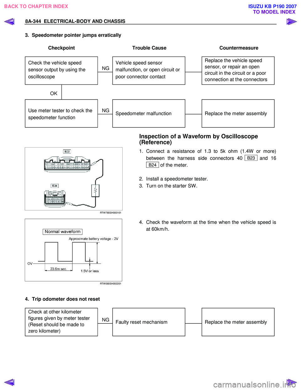
8A-344 ELECTRICAL-BODY AND CHASSIS
3. Speedometer pointer jumps erratically
Checkpoint Trouble Cause Countermeasure
Replace the vehicle speed
sensor, or repair an open
circuit in the circuit or a poor
connection at the connectors Vehicle speed sensor
malfunction, or open circuit or
poor connector contact
NG
Replace the meter assembly
Use meter tester to check the
speedometer function
Speedometer malfunction
NG
OK
Check the vehicle speed
sensor output by using the
oscilloscope
Inspection of a Waveform by Oscilloscope
(Reference)
RTW 780SH000101
1. Connect a resistance of 1.3 to 5k ohm (1.4W or more)
between the harness side connectors 40
B23 and 16
B24 of the meter.
2. Install a speedometer tester.
3. Turn on the starter SW .
RTW 580SH002201
4. Check the waveform at the time when the vehicle speed is
at 60km/h.
4. Trip odometer does not reset
Replace the meter assembly
Faulty reset mechanism
NG
Check at other kilometer
figures given by meter tester
(Reset should be made to
zero kilometer)
BACK TO CHAPTER INDEX
TO MODEL INDEXISUZU KB P190 2007
Page 5662 of 6020
SUPPLEMENTAL RESTRAINT SYSTEM 9A-27
5. Remove the passenger air bag assembly from the
vehicle. Refer to “Passenger Air Bag Assembl
y
Removal “.
6. Clear a space on the ground approximately 183 cm (six feet) in diameter where the fixture with
attached air bag assembly is to be placed fo
r
deployment. A paved outdoor location where there
is no activity is preferred. If an outdoor location is
not available, a space on the shop floor where
there is no activity and there is sufficient ventilation
is recommended. Ensure that no loose o
r
flammable objects are within the deployment area.
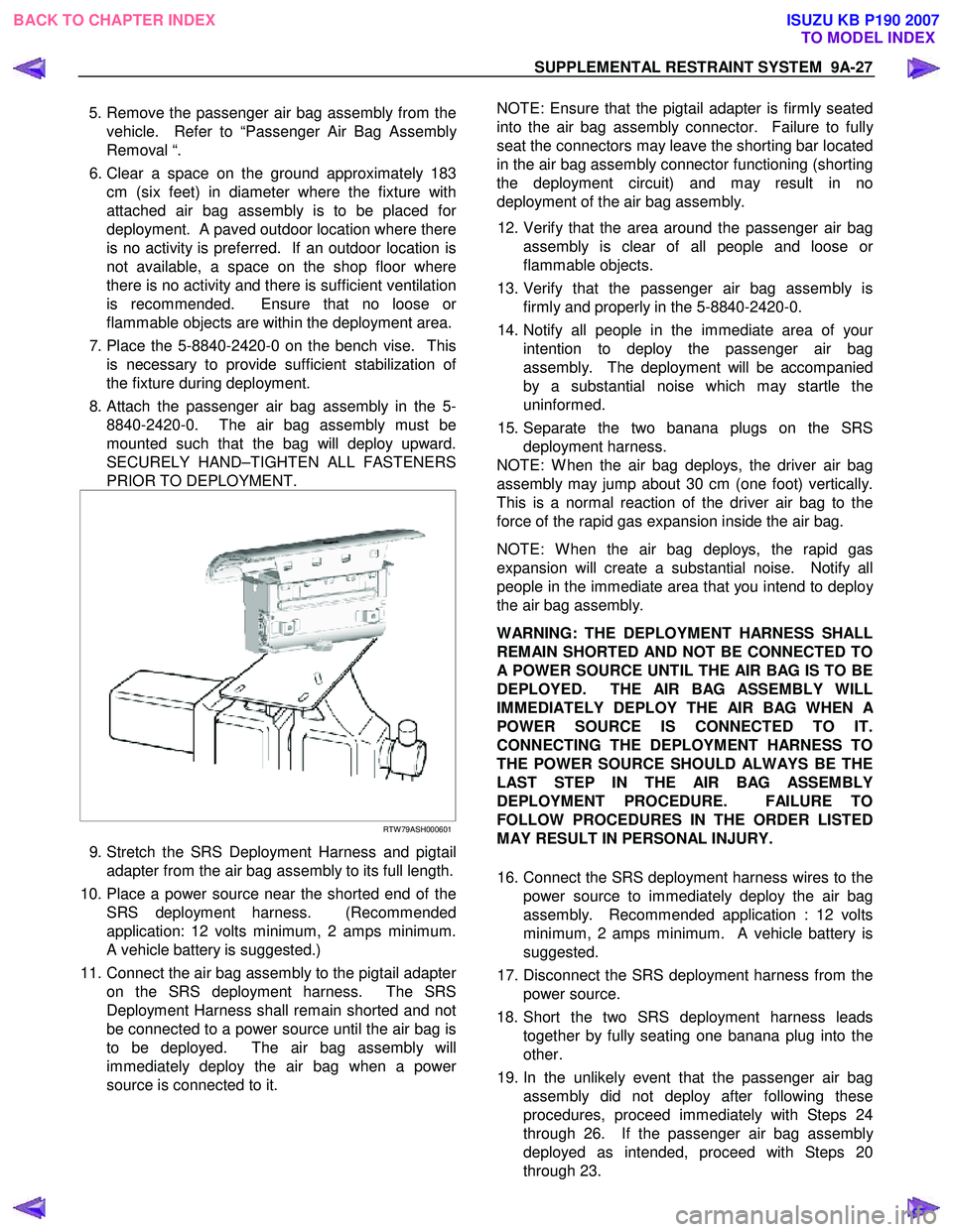
7. Place the 5-8840-2420-0 on the bench vise. This is necessary to provide sufficient stabilization o
f
the fixture during deployment.
8. Attach the passenger air bag assembly in the 5- 8840-2420-0. The air bag assembly must be
mounted such that the bag will deploy upward.
SECURELY HAND–TIGHTEN ALL FASTENERS
PRIOR TO DEPLOYMENT.
RTW 79ASH000601
9. Stretch the SRS Deployment Harness and pigtail
adapter from the air bag assembly to its full length.
10. Place a power source near the shorted end of the SRS deployment harness. (Recommended
application: 12 volts minimum, 2 amps minimum.
A vehicle battery is suggested.)
11. Connect the air bag assembly to the pigtail adapte
r
on the SRS deployment harness. The SRS
Deployment Harness shall remain shorted and not
be connected to a power source until the air bag is
to be deployed. The air bag assembly will
immediately deploy the air bag when a powe
r
source is connected to it.
NOTE: Ensure that the pigtail adapter is firmly seated
into the air bag assembly connector. Failure to full
y
seat the connectors may leave the shorting bar located
in the air bag assembly connector functioning (shorting
the deployment circuit) and may result in no
deployment of the air bag assembly.
12. Verify that the area around the passenger air bag assembly is clear of all people and loose o
r
flammable objects.
13. Verify that the passenger air bag assembly is firmly and properly in the 5-8840-2420-0.
14. Notify all people in the immediate area of you
r
intention to deploy the passenger air bag
assembly. The deployment will be accompanied
by a substantial noise which may startle the
uninformed.
15. Separate the two banana plugs on the SRS deployment harness.
NOTE: W hen the air bag deploys, the driver air bag
assembly may jump about 30 cm (one foot) vertically.
This is a normal reaction of the driver air bag to the
force of the rapid gas expansion inside the air bag.
NOTE: W hen the air bag deploys, the rapid gas
expansion will create a substantial noise. Notify all
people in the immediate area that you intend to deplo
y
the air bag assembly.
WARNING: THE DEPLOYMENT HARNESS SHALL
REMAIN SHORTED AND NOT BE CONNECTED TO
A POWER SOURCE UNTIL THE AIR BAG IS TO BE
DEPLOYED. THE AIR BAG ASSEMBLY WILL
IMMEDIATELY DEPLOY THE AIR BAG WHEN
A
POWER SOURCE IS CONNECTED TO IT.
CONNECTING THE DEPLOYMENT HARNESS TO
THE POWER SOURCE SHOULD ALWAYS BE THE
LAST STEP IN THE AIR BAG ASSEMBLY
DEPLOYMENT PROCEDURE. FAILURE TO
FOLLOW PROCEDURES IN THE ORDER LISTED
MAY RESULT IN PERSONAL INJURY.
16. Connect the SRS deployment harness wires to the power source to immediately deploy the air bag
assembly. Recommended application : 12 volts
minimum, 2 amps minimum. A vehicle battery is
suggested.
17. Disconnect the SRS deployment harness from the power source.
18. Short the two SRS deployment harness leads together by fully seating one banana plug into the
other.
19. In the unlikely event that the passenger air bag assembly did not deploy after following these
procedures, proceed immediately with Steps 24
through 26. If the passenger air bag assembl
y
deployed as intended, proceed with Steps 20
through 23.
BACK TO CHAPTER INDEX TO MODEL INDEXISUZU KB P190 2007