2007 ISUZU KB P190 wheel
[x] Cancel search: wheelPage 4878 of 6020
7D1-4 TRANSFER CONTROL SYSTEM
Summary of transfer control system
The transfer control system switches between the 2-wheel
drive (2H), 4-wheel drive high-speed (4H), 4-wheel drive low-
speed (4L), and neutral positions electrically when the driver
operates the switches.
This system has following functions.
1. Connection or disconnection of drive force distribution to the
front wheel front shaft (axle shaft). (The drive force
distribution to the front propeller is connected o
r
disconnected with the motor actuator.)
2. Try to repeat the connection or disconnection of the front wheel drive function as described above.
3. Option: Shift on the fly type only.
Instruction of connection or disconnection of the drive force transmission between the front wheel axle (axle shaft) and
front wheel. (The motor actuator connects or disconnects
the left front wheel and front wheel axle (axle shaft).)
4. Shifting of auxiliary transmission gears, connection o
r
disconnection of wheel and engine drive force (4H, 4L,
neutral).
5. Operation of the indicator on the instrument panel.
6. Transmission of the position signal to other controllers.
BACK TO CHAPTER INDEX
TO MODEL INDEX
ISUZU KB P190 2007
Page 4920 of 6020
7D1-46 TRANSFER CONTROL SYSTEM
Diagnosis
Before determining a trouble (Non-trouble mode)
1. When shifting from 2H to 4H:
1-1-1 When the flashing frequency of the 4WD indicator is changed from 2Hz to 4Hz (Shift on the fly) If the load is too large to shift the gears synchronously, the operation is repeated up to 3 times. If the shifting
is not effected after being repeated 3 times, the indicator frequency is changed from 2Hz to 4Hz. At the same
time, the actuator condition is changed to 2H, indicator flashes at 4Hz for 10 seconds, and then goes out.
Cause of excessive synchronous shifting load
• Extremely low temperature (the oil viscosity of the front differential increases requiring a large load for
synchronization).
• High speed (since the difference of relative revolutions of gears to be shifted synchronously is too large,
required work load per unit time becomes larger).
Step 1-1-1:
Stop the vehicle or decrease the speed and operate as required again.
1-1-2 When the flashing frequency of the 4WD indicator is changed from 2Hz to 4Hz (Rigid and free wheel
Hub) / Block out of meshing spline in transfer case.
Step 1-1-2:
Run the vehicle forward and backward several meters and operate as required again.
1-2 When the flashing of 4WD indicator at 2Hz continues more than 11.5 seconds (repetition of 3 times of
above No.1 is counted) (Shift on the fly)
If there is difference of revolutions and phases between the front wheel and the axle, connecting the front
wheel and axle is difficult.
Until shifting in the transfer and connection of the front wheel and axle are completed
∗, the indicator flashes at
a frequency of 2Hz. In the above case, the indicator continues flashing at a frequency of 2Hz until the
connection of the front axle is completed. (If the shifting in the transfer is not completed, the flashing
frequency is changed to 4Hz (above No.1).)
By correcting the difference of relative revolutions and deviation of phases, the shifting can be completed.
Step 1-2:
While the vehicle is running, check it is safe around the vehicle and then accelerate or decelerate the
vehicle while going straight.
When the vehicle is at a stop, run the vehicle forward and backward several meters.
2. When shifting from 4H to 2H
2-1 When 4WD indicator continues flashing at 2Hz
W hen shifting from 4H to 2H, the 4W D indicator continues flashing at 2Hz until separation in the transfer and
the separation of the front wheel axle are completed∗. W hen torsional torque is accumulated in the drive
system, separation in the transfer and separation of the front axle∗ is difficult. In such a case, they can be
separated by removing the torsional torque of the drive system.
Step 2-1:
While the vehicle is running, check it is safe around the vehicle and then accelerate or decelerate the
vehicle while going straight.
When the vehicle is in stop, run the vehicle several meters forward and backward.
∗: Shift on the fly only.
BACK TO CHAPTER INDEX
TO MODEL INDEX
ISUZU KB P190 2007
Page 4950 of 6020
8A-12 ELECTRICAL-BODY AND CHASSIS
ABBREVIATIONS
Abbreviation Meaning of abbreviation Abbreviation Meaning of abbreviation
A Ampere (S) kW Kilowatt
ABS Anti-lock brake system LH Left hand
ASM Assembly LW B Long wheel base
AC Alternating current MPI Multipart fuel injection
A/C Air conditioner M/T Manual transmission
ACC Accessories PA Passenger
CARB Carburetor PIM Power train interface module
C/B Circuit breaker PJT Projector
CKP Crankshaft position QOS Quick On Start system
CSD Cold start device RH Right hand
DIS Direct ignition system RR Rear
DR Driver RW AL Rear wheel anti-lock brake system
DRM Data Recording Module SCV Suction control valve
EHCU Electronic Hydraulic control Unit SRS Supplemental restraint system
ECGI Electronic control gasoline injection ST Start
ECM Engine control module STD Standard
ECU Electronic control unit SW Switch
EFE Early fuel evaporation SW B Short wheel base
EGR Exhaust gas recirculation TCM Transmission control module
2W D Two-wheel drive TCCM Transfer case control module
4W D Four-wheel drive V Volt
FL Fusible link VSV Vacuum switching valve
FRT Front W W att (S)
H/L Headlight W OT W ide open throttle
W/ With HVAC
Heater, Ventilation, and Air
Conditioning W /O W ithout
IC Integrated circuit W /S W eld Splice
IG Ignition
BACK TO CHAPTER INDEX
TO MODEL INDEXISUZU KB P190 2007
Page 5107 of 6020
ELECTRICAL-BODY AND CHASSIS 8A-169
Installation
Follow the removal procedure in the reverse order to install the
headlight.
Pay close attention to the important points mentioned in the
following paragraphs.
Connector
Be absolutely sure that the headlight connector is securely
connected.
This will prevent a contact and an open circuit.
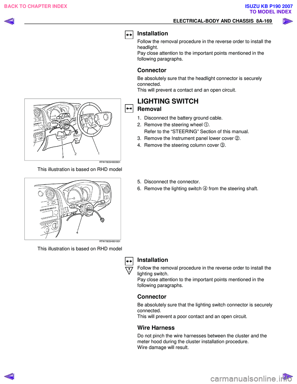
RTW 780SH000901
This illustration is based on RHD model
LIGHTING SWITCH
Removal
1. Disconnect the battery ground cable.
2. Remove the steering wheel
1.
Refer to the “STEERING” Section of this manual.
3. Remove the Instrument panel lower cover
2.
4. Remove the steering column cover
3.
RTW 780SH001001
This illustration is based on RHD model
5. Disconnect the connector.
6. Remove the lighting switch
4 from the steering shaft.
Installation
Follow the removal procedure in the reverse order to install the
lighting switch.
Pay close attention to the important points mentioned in the
following paragraphs.
Connector
Be absolutely sure that the lighting switch connector is securely
connected.
This will prevent a poor contact and an open circuit.
Wire Harness
Do not pinch the wire harnesses between the cluster and the
meter hood during the cluster installation procedure.
W ire damage will result.
BACK TO CHAPTER INDEX TO MODEL INDEXISUZU KB P190 2007
Page 5111 of 6020
ELECTRICAL-BODY AND CHASSIS 8A-173
RTW 780SH000901
RTW 780SH001001
HEADLIGHT BEAM SWITCH
(COMBINATION SWITCH)
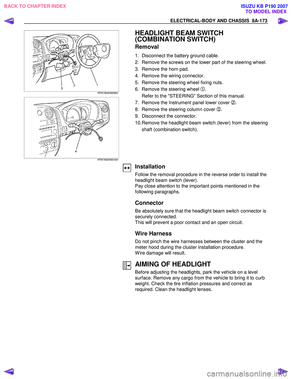
Removal
1. Disconnect the battery ground cable.
2. Remove the screws on the lower part of the steering wheel.
3. Remove the horn pad.
4. Remove the wiring connector.
5. Remove the steering wheel fixing nuts.
6. Remove the steering wheel
1.
Refer to the "STEERING" Section of this manual.
7. Remove the Instrument panel lower cover
2.
8. Remove the steering column cover
3.
9. Disconnect the connector.
10. Remove the headlight beam switch (lever) from the steering shaft (combination switch).
Installation
Follow the removal procedure in the reverse order to install the
headlight beam switch (lever).
Pay close attention to the important points mentioned in the
following paragraphs.
Connector
Be absolutely sure that the headlight beam switch connector is
securely connected.
This will prevent a poor contact and an open circuit.
Wire Harness
Do not pinch the wire harnesses between the cluster and the
meter hood during the cluster installation procedure.
W ire damage will result.
AIMING OF HEADLIGHT
Before adjusting the headlights, park the vehicle on a level
surface. Remove any cargo from the vehicle to bring it to curb
weight. Check the tire inflation pressures and correct as
required. Clean the headlight lenses.
BACK TO CHAPTER INDEX TO MODEL INDEXISUZU KB P190 2007
Page 5137 of 6020
ELECTRICAL-BODY AND CHASSIS 8A-199
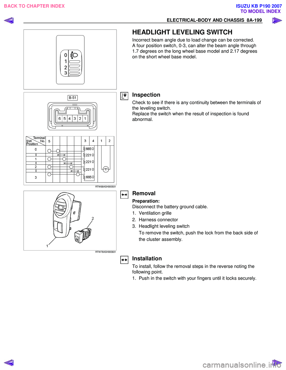
HEADLIGHT LEVELING SWITCH
Incorrect beam angle due to load change can be corrected.
A four position switch, 0-3, can alter the beam angle through
1.7 degrees on the long wheel base model and 2.17 degrees
on the short wheel base model.
RTW 68ASH000501
Inspection
Check to see if there is any continuity between the terminals of
the leveling switch.
Replace the switch when the result of inspection is found
abnormal.
RTW 78ASH000601
Removal
Preparation:
Disconnect the battery ground cable.
1. Ventilation grille
2. Harness connector
3. Headlight leveling switch To remove the switch, push the lock from the back side of
the cluster assembly.
Installation
To install, follow the removal steps in the reverse noting the
following point.
1. Push in the switch with your fingers until it locks securely.
BACK TO CHAPTER INDEX TO MODEL INDEXISUZU KB P190 2007
Page 5171 of 6020
ELECTRICAL-BODY AND CHASSIS 8A-233
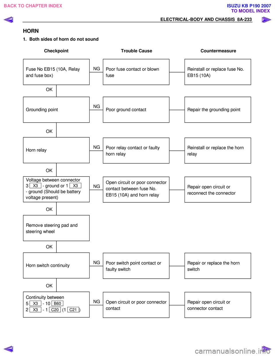
HORN
1. Both sides of horn do not sound
Checkpoint Trouble Cause Countermeasure
Repair the grounding point
Poor ground contact
NG
Horn relay
Grounding point
Reinstall or replace fuse No.
EB15 (10A)
Fuse No EB15 (10A, Relay
and fuse box)
Poor fuse contact or blown
fuse
NG
OK
OK
Reinstall or replace the horn
relay
Poor relay contact or faulty
horn relay
NG
Voltage between connector
3
X3 - ground or 1 X3
- ground (Should be battery
v oltage present) OK
Repair open circuit or
reconnect the connector
Open circuit or poor connector
contact between fuse No.
EB15 (10A) and horn relay
NG
Remov e steering pad and
steering wheel
OK
Horn switch continuity
OK
Repair or replace the horn
switch
Poor switch point contact or
faulty switch
NG
Continuity between
5
X3 - 10 B60
2
X3 - 1 C20 (1 C21 )
OK
Repair open circuit or
connector contact
Open circuit or poor connector
contact
NG
BACK TO CHAPTER INDEX
TO MODEL INDEXISUZU KB P190 2007
Page 5177 of 6020
ELECTRICAL-BODY AND CHASSIS 8A-239
Bulb
Be absolutely sure that the rear combination light bulb is
correctly installed.
This will prevent a poor contact and an open circuit.
RTW 780SH000901
This illustration is based on RHD model
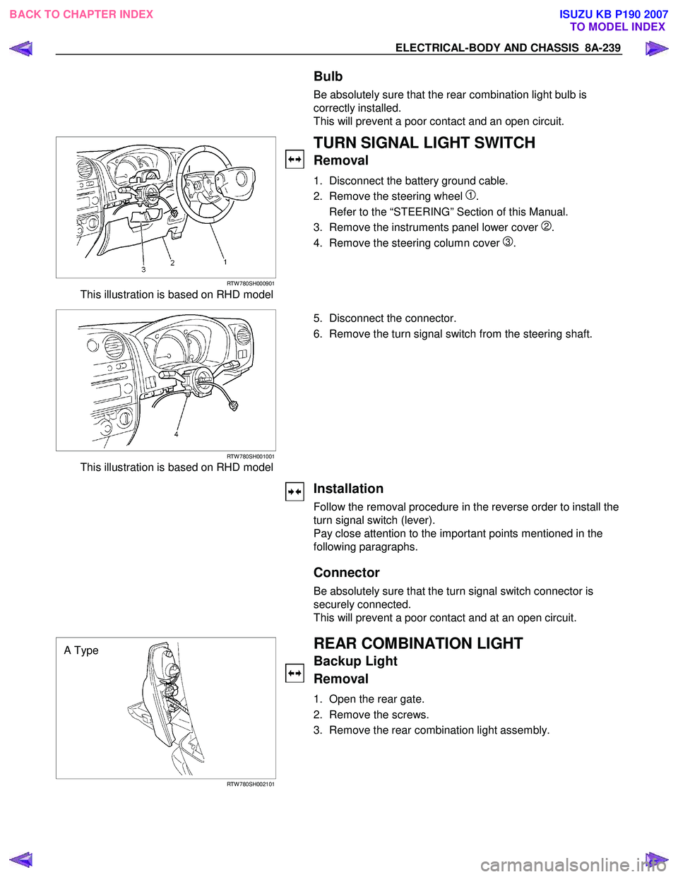
TURN SIGNAL LIGHT SWITCH
Removal
1. Disconnect the battery ground cable.
2. Remove the steering wheel
1.
Refer to the “STEERING” Section of this Manual.
3. Remove the instruments panel lower cover
2.
4. Remove the steering column cover
3.
RTW 780SH001001
This illustration is based on RHD model
5. Disconnect the connector.
6. Remove the turn signal switch from the steering shaft.
Installation
Follow the removal procedure in the reverse order to install the
turn signal switch (lever).
Pay close attention to the important points mentioned in the
following paragraphs.
Connector
Be absolutely sure that the turn signal switch connector is
securely connected.
This will prevent a poor contact and at an open circuit.
A Type
RTW 780SH002101
REAR COMBINATION LIGHT
Backup Light
Removal
1. Open the rear gate.
2. Remove the screws.
3. Remove the rear combination light assembly.
BACK TO CHAPTER INDEX TO MODEL INDEXISUZU KB P190 2007