Page 4803 of 6020

CLUTCH 7C-25
201RW 012
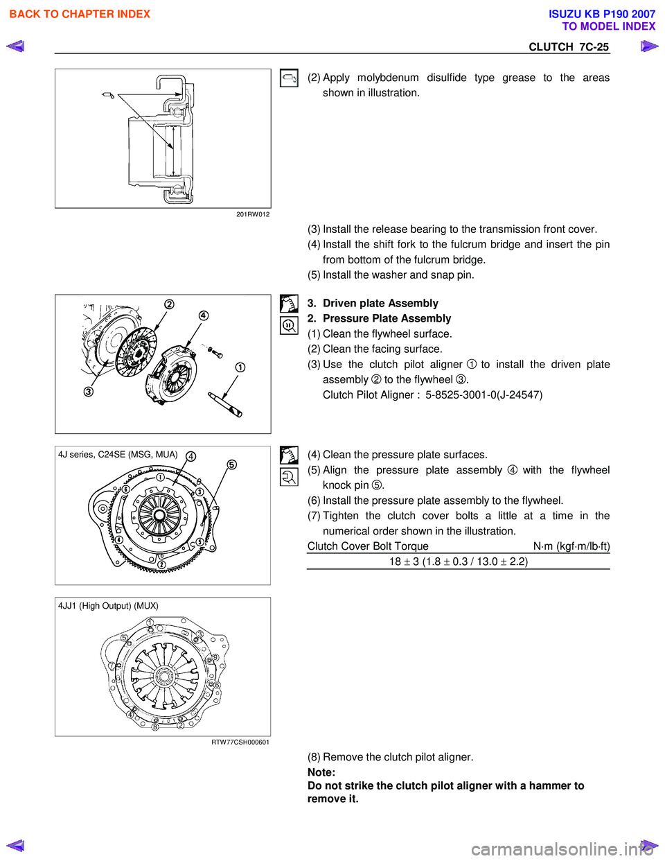
(2) Apply molybdenum disulfide type grease to the areas shown in illustration.
(3) Install the release bearing to the transmission front cover.
(4) Install the shift fork to the fulcrum bridge and insert the pin from bottom of the fulcrum bridge.
(5) Install the washer and snap pin.
3. Driven plate Assembly
2. Pressure Plate Assembly
(1) Clean the flywheel surface.
(2) Clean the facing surface.
(3) Use the clutch pilot aligner
1 to install the driven plate
assembly
2 to the flywheel 3.
Clutch Pilot Aligner : 5-8525-3001-0(J-24547)
4 4J series, C24SE (MSG, MUA)
(4) Clean the pressure plate surfaces.
(5) Align the pressure plate assembly
4 with the flywheel
knock pin
5.
(6) Install the pressure plate assembly to the flywheel.
(7) Tighten the clutch cover bolts a little at a time in the numerical order shown in the illustration.
Clutch Cover Bolt Torque N⋅m (kgf ⋅m/lb ⋅ft)
18 ± 3 (1.8 ± 0.3 / 13.0 ± 2.2)
4JJ1 (High Output) (MUX)
RTW 77CSH000601
(8) Remove the clutch pilot aligner.
Note:
Do not strike the clutch pilot aligner with a hammer to
remove it.
BACK TO CHAPTER INDEX
TO MODEL INDEX
ISUZU KB P190 2007
Page 4805 of 6020

CLUTCH 7C-27
RTW 67CSH000101
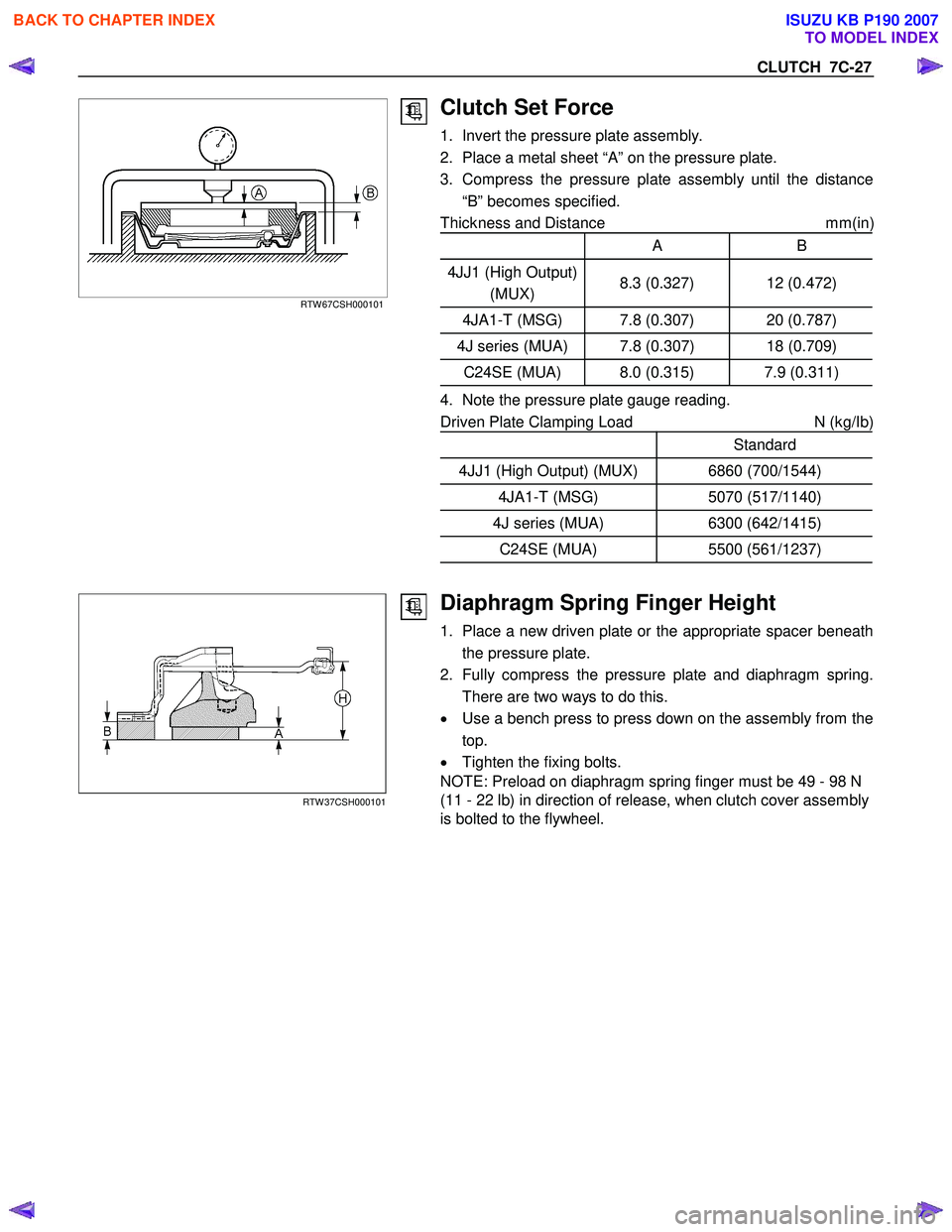
Clutch Set Force
1. Invert the pressure plate assembly.
2. Place a metal sheet “A” on the pressure plate.
3. Compress the pressure plate assembly until the distance “B” becomes specified.
Thickness and Distance mm(in
)
A B
4JJ1 (High Output)
(MUX) 8.3 (0.327) 12 (0.472)
4JA1-T (MSG) 7.8 (0.307) 20 (0.787)
4J series (MUA) 7.8 (0.307) 18 (0.709)
C24SE (MUA) 8.0 (0.315) 7.9 (0.311)
4. Note the pressure plate gauge reading.
Driven Plate Clamping Load N (kg/Ib)
Standard
4JJ1 (High Output) (MUX) 6860 (700/1544)
4JA1-T (MSG) 5070 (517/1140)
4J series (MUA) 6300 (642/1415)
C24SE (MUA) 5500 (561/1237)
RTW 37CSH000101
Diaphragm Spring Finger Height
1. Place a new driven plate or the appropriate spacer beneath
the pressure plate.
2. Fully compress the pressure plate and diaphragm spring. There are two ways to do this.
• Use a bench press to press down on the assembly from the
top.
• Tighten the fixing bolts.
NOTE: Preload on diaphragm spring finger must be 49 - 98 N
(11 - 22 lb) in direction of release, when clutch cover assembly
is bolted to the flywheel.
BACK TO CHAPTER INDEX
TO MODEL INDEX
ISUZU KB P190 2007
Page 4809 of 6020

CLUTCH 7C-31
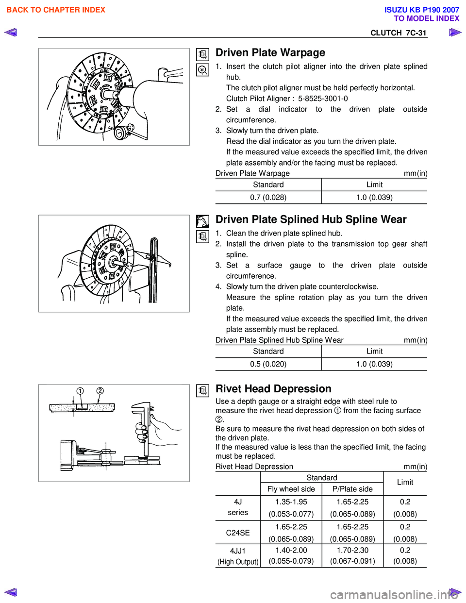
Driven Plate Warpage
1. Insert the clutch pilot aligner into the driven plate splinedhub.
The clutch pilot aligner must be held perfectly horizontal.
Clutch Pilot Aligner : 5-8525-3001-0
2. Set a dial indicator to the driven plate outside circumference.
3. Slowly turn the driven plate.
Read the dial indicator as you turn the driven plate.
If the measured value exceeds the specified limit, the driven plate assembly and/or the facing must be replaced.
Driven Plate W arpage mm(in)
Standard Limit
0.7 (0.028)1.0 (0.039)
Driven Plate Splined Hub Spline Wear
1. Clean the driven plate splined hub.
2. Install the driven plate to the transmission top gear shaft spline.
3. Set a surface gauge to the driven plate outside circumference.
4. Slowly turn the driven plate counterclockwise.
Measure the spline rotation play as you turn the driven plate.
If the measured value exceeds the specified limit, the driven plate assembly must be replaced.
Driven Plate Splined Hub Spline W ear mm(in)
Standard Limit
0.5 (0.020)1.0 (0.039)
Rivet Head Depression
Use a depth gauge or a straight edge with steel rule to
measure the rivet head depression
1 from the facing surface
2.
Be sure to measure the rivet head depression on both sides of
the driven plate.
If the measured value is less than the specified limit, the facing
must be replaced.
Rivet Head Depression mm(in)
Standard
Fly wheel side P/Plate side Limit
4J
series 1.35-1.95
(0.053-0.077) 1.65-2.25
(0.065-0.089) 0.2
(0.008)
C24SE 1.65-2.25
(0.065-0.089) 1.65-2.25
(0.065-0.089) 0.2
(0.008)
4JJ1
(High Output)
1.40-2.00
(0.055-0.079) 1.70-2.30
(0.067-0.091) 0.2
(0.008)
BACK TO CHAPTER INDEX
TO MODEL INDEX
ISUZU KB P190 2007
Page 4824 of 6020
7C-46 CLUTCH
Checkpoint Problem Countermeasure
Crankshaft pilot bearingReplace the pilot bearingTop gear shaft wobble is
causing pilot bearing wear
Repair or replace the flywheelFlywheel unevenly worn
NG
NG
OK
OKFlywheel
Continued from the previous page
BACK TO CHAPTER INDEX
TO MODEL INDEX
ISUZU KB P190 2007
Page 4826 of 6020
7C-48 CLUTCH
Checkpoint Problem Countermeasure
Replace the driven plate
assemblyW arpage and/or uneven wear
Replace the driven plate
assemblyLoose facing rivets
NG
NG
OKDriven plate
Continued from the previous page
FlywheelRepair or replace the flywheelFlywheel uneven wear
NG
OK
BACK TO CHAPTER INDEX
TO MODEL INDEX
ISUZU KB P190 2007
Page 4833 of 6020
TRANSFER CASE 7D-3
General Description
RTW 57ALF000301
The transfer case is used to provide a means of
providing power flow to the front axle. The transfer case
also provides a means of disconnecting the front axle,
providing better fuel economy and quieter operation
when the vehicle is driven on improved roads where fou
r
wheel drive is not required. In addition, the transfer case
provides an additional gear reduction when placed in lo
w
range, which is useful when difficult off-road conditions
are encountered.
Use the 4W D switch on the center cluster panel to select
the drive range. The 4W D indicator lamp will be lit when
4W D is selected.
BACK TO CHAPTER INDEX
TO MODEL INDEX
ISUZU KB P190 2007
Page 4871 of 6020
TRANSFER CASE 7D-41
Main Data and Specifications
General Specifications
Type Synchronized type gears shifting between the 2 and 4 wheel drive mode.
Planetary type gears shifting between “low" and “high".
Control method Remote control with the button switch on the instrument panel for gears
shifting among “2H", “4H" and “4L".
Gear ratio High; 1.000
Low; 2.482
Oil capacity 1.3 lit. (1.37 US qt)
Type of lubricant BESCO GEAR OIL TRANSAXLE (5W -30)
Refer to Section 0B
Torque Specifications
N⋅m (kgf ⋅m/lb ⋅ft)
RTW 67DLF000201
BACK TO CHAPTER INDEX
TO MODEL INDEX
ISUZU KB P190 2007
Page 4877 of 6020
TRANSFER CONTROL SYSTEM 7D1-3
General Description
RTW 77DLF000501
Transfer Position and Drive Mode
Three drive modes can be selected through operation of 4W D switch.
Transfer Position 4WD SWITCH Mode Drive mode
2H RW D Rear wheel drive
HIGH
4H 4W D (HIGH) High-speed mechanical
lock-up four wheel drive
LOW 4L 4W D (LOW ) Low-speed mechanical
lock-up four wheel drive
NEUTRAL 2H & 4L (10 Sec) NEUTRAL Towed by other vehicle
BACK TO CHAPTER INDEX
TO MODEL INDEX
ISUZU KB P190 2007