Page 4476 of 6020

4. Install the transmission mount.
Bolt torque (rubber to transmission) :
50N·m (5.1 kgf·m/37 lb·ft)
Nut torque (rubber to crossmember) :
52N")
7A3-22 ON-VEHICLE SERVICE (JR405E)
4. Install the transmission mount.
Bolt torque (rubber to transmission) :
50N·m (5.1 kgf·m/37 lb·ft)
Nut torque (rubber to crossmember) :
52N·m (5.3 kgf·m/38 lb·ft)
5. Install the 3rd crossmember.
Bolt and Nut torque : 67 N·m (6.8 kgf·m/49 lb·ft)
Bolt torque : 50 N·m (5.1 kgf·m/37 lb·ft)
6. Install the automatic transmission fluid cooling pipe.
7. Install the torque converter bolts.
Bolt torque : 29 N·m (3.0 kgf·m/22 lb·ft)
8. Install the undercover.
Bolt torque : 9 N·m (0.9 kgf·m/78 lb·in)
9. Install the ATF level dipstick and tube.
10. Install the fuel hose bracket.
Bolt torque : 10 N·m (1.0 kgf·m/87 lb·in)
11. Tighten the nuts securing the exhaust manifold and the exhaust pipe.
Bolt torque : 43 N·m (4.4 kgf·m/32 lb·ft)
12. Install the rear propeller shaft assembly.
Flange bolt torque : 59 N·m (6.0 kgf·m/43 lb·ft)
Center bearing bracket bolt torque :
69 N·m (7.0 kgf·m/51 lb·ft)
13. Install the shift cable.
14. Connect the negative battery cable.
15. Remove the safety stands.
16. Remove the wheels blocks.
Torque Specifications
N ⋅
⋅⋅
⋅
m (kgf ⋅
⋅⋅
⋅
m/lb ⋅
⋅⋅
⋅
ft)
mm
RTW 67ALF000301
BACK TO CHAPTER INDEX
TO MODEL INDEX
ISUZU KB P190 2007
Page 4657 of 6020
MANUAL TRANSMISSION 7B1-51
TROUBLESHOOTING
1. ABNORMAL NOISE
1) NOISY IN NEUTRAL
Checkpoint Trouble Cause Countermeasure
Replenish or replace the gear
oilInsufficient or improper gear
oil
NG
Mainshaft splines
Synchronizer clutch hub
splinesReplace the main shaft and
the synchronizer clutch hub
Replace the gear(s)
Replace the flywheel pilot
W orn splines
W orn or scuffed gear tooth
contact surfaces
Flywheel pilot bearingW orn flywheel pilot bearing
Bearings (Mainshaft,
countershaft, and transfer
shaft)
Gears (Mainshaft,
countershaft, reverse idler
gear and transfer gears)
Replace the bearing(s)W orn or broken bearing(s)
OK NG
NG
NG
NG
OK
OK
OK
Gear oil
TransmissionRealign the transmissionTransmission misalignment
OK
NG
BACK TO CHAPTER INDEX
TO MODEL INDEX
ISUZU KB P190 2007
Page 4711 of 6020
MANUAL TRANSMISSION 7B1-105
TROUBLESHOOTING
1. ABNORMAL NOISE
1) NOISY IN NEUTRAL
Checkpoint Trouble Cause Countermeasure
Replenish or replace the gear
oilInsufficient or improper gear
oil
NG
Mainshaft splines
Synchronizer clutch hub
splinesReplace the main shaft and
the synchronizer clutch hub
Replace the gear(s)
Replace the flywheel pilot
W orn splines
W orn or scuffed gear tooth
contact surfaces
Flywheel pilot bearingW orn flywheel pilot bearing
Bearings (Mainshaft,
countershaft, and transfer
shaft)
Gears (Mainshaft,
countershaft, reverse idler
gear and transfer gears)
Replace the bearing(s)W orn or broken bearing(s)
OK NG
NG
NG
NG
OK
OK
OK
Gear oil
TransmissionRealign the transmissionTransmission misalignment
OK
NG
BACK TO CHAPTER INDEX
TO MODEL INDEX
ISUZU KB P190 2007
Page 4723 of 6020

Troubleshooting
ConditionPossible Cause Correction
Abnormal Noise (Noisy in Neutral) Insufficient or improper lubricant Replenish or replace lubricant Flywheel pilo")
7B1-4 Manual Transmission (MUX)
Troubleshooting
ConditionPossible Cause Correction
Abnormal Noise (Noisy in Neutral) Insufficient or improper lubricant Replenish or replace lubricant Flywheel pilot bearing worn or
broken Replace flywheel pilot bearing
Bearing(s) worn or broken (Input
shaft, counter shaft, and output
shaft) Replace bearing(s)
Gear tooth contact surfaces worn or
scuffed (Input shaft, counter shaft,
output shaft, and reverse idler gear) Replace gear(s)
Spline worn (Input shaft, output
shaft, counter shaft, and
synchronizer clutch hub) Replace worn parts
Transmission misalignment Realign transmission
Abnormal Noise (Noisy Operation) Insufficient or improper lubricant (Metallic rattling) Replenish or replace lubricant
Bearing(s) worn or broken (Hissing,
thumping, or bumping) Replace bearing(s)
Gear(s) worn, chipped, or cracked
(Growling, humming, or grinding) Replace gear(s)
Gears seizing on thrust face or
inner face free running (Squealing
at high speeds) Replace gear(s)
Gears lack of backlash between
meshing (Gear whining) Replace gear(s)
Hard Shifting Insufficient or improper lubricant Replenish or replace lubricant
Improper clutch pedal free play Readjust clutch pedal free play
Hard operating of change lever
caused insufficient grease Repair or regrease change lever
assembly
Change lever sliding portions worn Repair or replace applicable parts and regrease
Shift block sleeve movement failure Repair or replace sleeve
Shift rod and/or quadrant box
sliding face worn Replace worn parts
Shift arm and/or synchronizer
sleeve groove worn Replace worn parts
Collar, and/or gear thrust faces
worn (Input shaft and counter shaft
thrust play) Replace worn parts
Synchronizer parts worn Replace worn parts
BACK TO CHAPTER INDEX
TO MODEL INDEX
ISUZU KB P190 2007
Page 4782 of 6020

7C-4 CLUTCH
The clutch assembly consists of the pressure plate, the clutch cover, the diaphragm spring pivot pin and the driven
plate assembly.
The clutch pedal is connected to the release bearing through the shift fork.
The driven plate assembly is installed between the flywheel and the pressure plate.
For models with MSG transmission and MUA transmission, the push-type clutch is used.
Diaphragm spring pressure holds the driven plate against flywheel and the pressure plate to provide the friction
necessary to engage the clutch.
Depressing the clutch pedal moves the shift fork against the release bearing.
The release bearing forces the diaphragm to overcome the force of the diaphragm spring and separate the driven
plate from the flywheel and pressure plate to disengage the clutch.
For model with MUX transmission, the pull-type clutch is used. The pull-type clutch is disengaged by pulling the
release lever (release bearing) to disengage the pressure plate.
BACK TO CHAPTER INDEX
TO MODEL INDEX
ISUZU KB P190 2007
Page 4800 of 6020
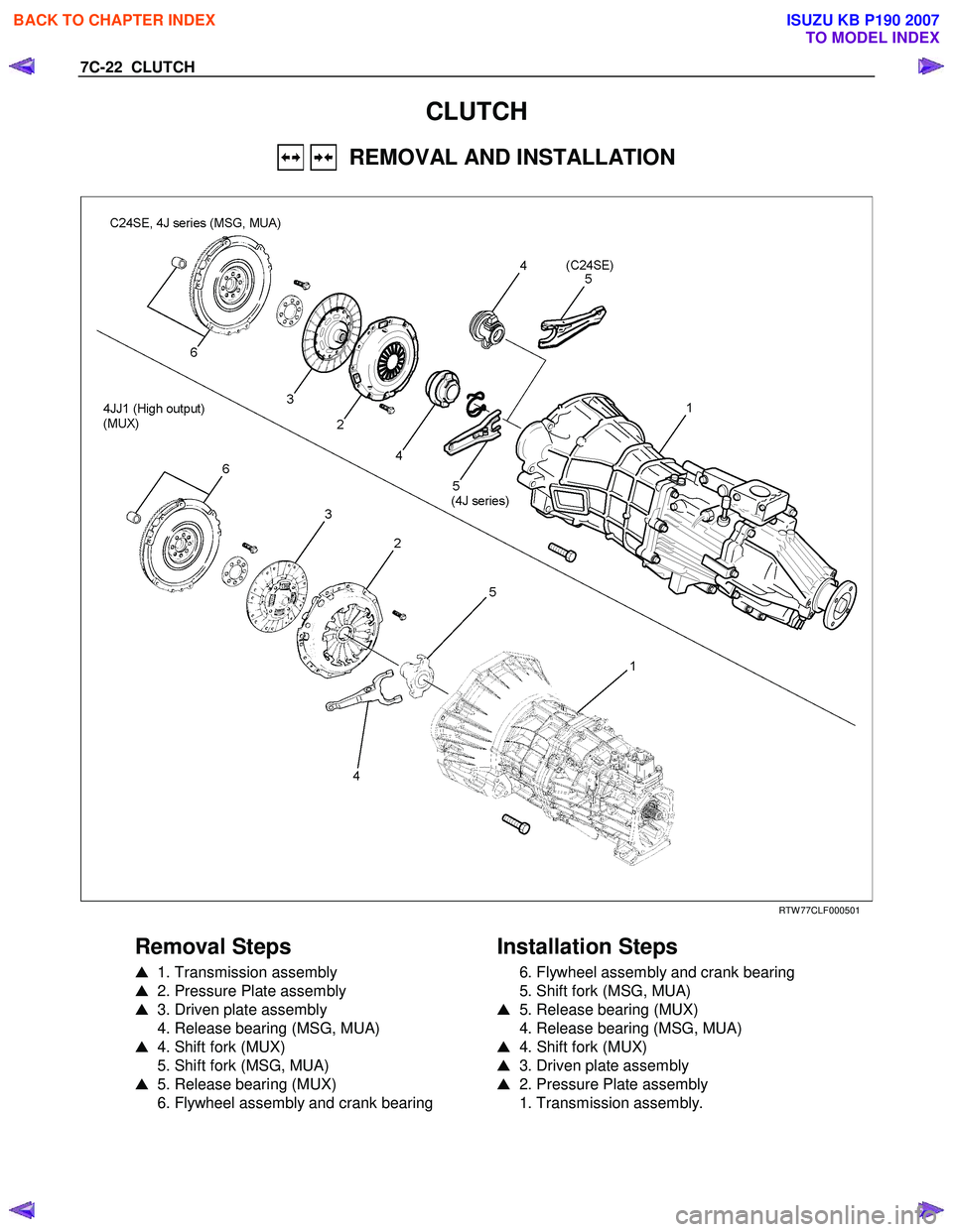
7C-22 CLUTCH
CLUTCH
REMOVAL AND INSTALLATION
RTW 77CLF000501
Removal Steps
� 1. Transmission assembly
� 2. Pressure Plate assembly
� 3. Driven plate assembly
4. Release bearing (MSG, MUA)
� 4. Shift fork (MUX)
5. Shift fork (MSG, MUA)
� 5. Release bearing (MUX)
6. Flywheel assembly and crank bearing
Installation Steps
6. Flywheel assembly and crank bearing
5. Shift fork (MSG, MUA)
� 5. Release bearing (MUX)
4. Release bearing (MSG, MUA)
� 4. Shift fork (MUX)
� 3. Driven plate assembly
� 2. Pressure Plate assembly
1. Transmission assembly.
BACK TO CHAPTER INDEX
TO MODEL INDEX
ISUZU KB P190 2007
Page 4801 of 6020
CLUTCH 7C-23
Important Operations - Removal
1. Transmission Assembly
Refer to “MANUAL TRANSMISSION” of section 7B and 7B1
for “REMOVAL AND INSTALLATION” procedure.
2. Pressure Plate Assembly
3. Driven Plate Assembly
(1) Use the clutch pilot aligner
1 to prevent the driven plate
assembly
2 from falling free.
Clutch Pilot Aligner : 5-8525-3001-0(J-24547)
4J series, C24SE (MSG, MUA)
(2) Loosen the clutch cover bolts in the numerical order shown
in the illustration.
(3) Remove the pressure plate assembly
3 from the flywheel.
(4) Remove the driven plate from the flywheel.
4JJ1 (High Output) (MUX)
RTW 77CSH000601
RTW 77CSH000801
4. Shift Fork (MUX)
5. Release Bearing (MUX)
(1) Remove the shift fork snap pin (2).
(2) Remove the shift fork pin and shift fork (3) from the fulcrum bridge.
(3) Remove the release bearing (1) from the transmission case.
BACK TO CHAPTER INDEX
TO MODEL INDEX
ISUZU KB P190 2007
Page 4802 of 6020

(1) Remove flywheel assembly and crankshaft bearing. Do not remove except for replacement.
(2) Use the remover 5-8840-2000-0")
7C-24 CLUTCH
015RW 053
6. Flywheel Assembly and Crank Bearing (MUX)
(1) Remove flywheel assembly and crankshaft bearing. Do not remove except for replacement.
(2) Use the remover 5-8840-2000-0 (J-5822) and sliding hammer 5-8840-0019-0 (J-23907) to remove the crankshaft
bearing
Important Operations - Installation
Follow the removal procedure in reverse order to perform the
installation procedure.
Pay careful attention to the important points during the
installation procedure.
015RW 054
6. Flywheel Assembly and Crank Bearing (MUX)
(1) Install flywheel assembly and crankshaft bearing. Use the installer 5-8840-0125-0 (J-26516-A) and driver handle 5-
8840-0007-0 (J-8092) to install the crankshaft bearing then
clean and lubricate with grease.
015RS047
(2) Install new flywheel fixing bolts in the order illustrated and tighten them to the specified torque. N⋅m (kg ⋅m/lb ⋅ft)
MUX 54 (5.5/40)
NOTE: Do not reuse the bolt and do not apply oil or thread lock
to the bolt.
RTW 77CSH000701
5. Release Bearing (MUX)
4. Shift Fork (MUX)
(1)
Apply molybdenum disulfide type grease to the pin hole
inner circumferences and thrust surfaces.
BACK TO CHAPTER INDEX
TO MODEL INDEX
ISUZU KB P190 2007
 NOISY IN NEUTRAL
Checkpoint Trouble Cause Countermeasure
Replenish or replace the gear
oilInsufficient or improper")
 NOISY IN NEUTRAL
Checkpoint Trouble Cause Countermeasure
Replenish or replace the gear
oilInsufficient or improper")