2007 ISUZU KB P190 wheel
[x] Cancel search: wheelPage 4362 of 6020
7A2-78 TRANSMISSION CONTROL SYSTEM (JR405E)
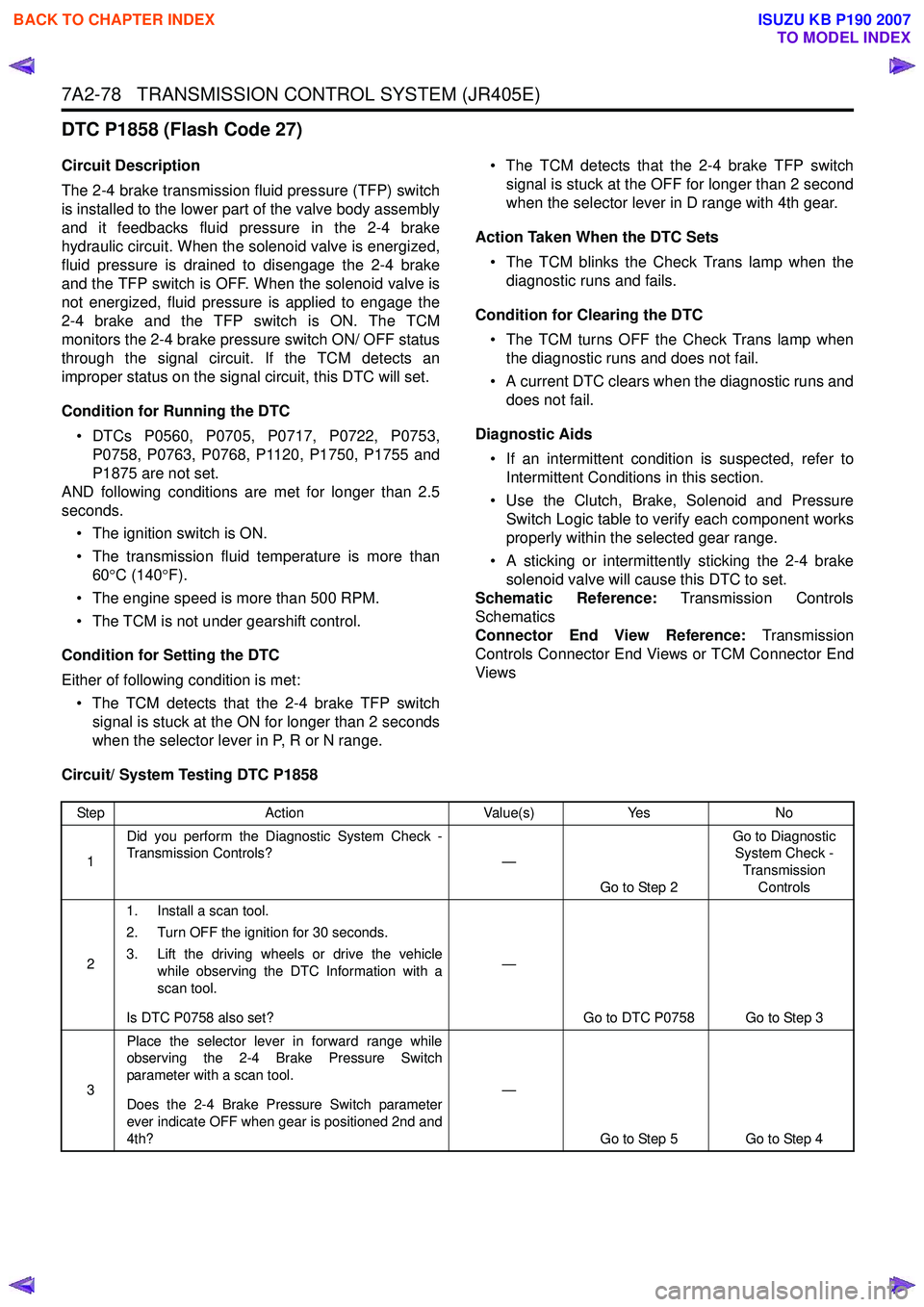
DTC P1858 (Flash Code 27)
Circuit Description
The 2-4 brake transmission fluid pressure (TFP) switch
is installed to the lower part of the valve body assembly
and it feedbacks fluid pressure in the 2-4 brake
hydraulic circuit. When the solenoid valve is energized,
fluid pressure is drained to disengage the 2-4 brake
and the TFP switch is OFF. When the solenoid valve is
not energized, fluid pressure is applied to engage the
2-4 brake and the TFP switch is ON. The TCM
monitors the 2-4 brake pressure switch ON/ OFF status
through the signal circuit. If the TCM detects an
improper status on the signal circuit, this DTC will set.
Condition for Running the DTC • DTCs P0560, P0705, P0717, P0722, P0753, P0758, P0763, P0768, P1120, P1750, P1755 and
P1875 are not set.
AND following conditions are met for longer than 2.5
seconds.
• The ignition switch is ON.
• The transmission fluid temperature is more than 60 °C (140 °F).
• The engine speed is more than 500 RPM.
• The TCM is not under gearshift control.
Condition for Setting the DTC
Either of following condition is met: • The TCM detects that the 2-4 brake TFP switch signal is stuck at the ON for longer than 2 seconds
when the selector lever in P, R or N range. • The TCM detects that the 2-4 brake TFP switch
signal is stuck at the OFF for longer than 2 second
when the selector lever in D range with 4th gear.
Action Taken When the DTC Sets • The TCM blinks the Check Trans lamp when the diagnostic runs and fails.
Condition for Clearing the DTC • The TCM turns OFF the Check Trans lamp when the diagnostic runs and does not fail.
• A current DTC clears when the diagnostic runs and does not fail.
Diagnostic Aids • If an intermittent condition is suspected, refer to Intermittent Conditions in this section.
• Use the Clutch, Brake, Solenoid and Pressure Switch Logic table to verify each component works
properly within the selected gear range.
• A sticking or intermittently sticking the 2-4 brake solenoid valve will cause this DTC to set.
Schematic Reference: Transmission Controls
Schematics
Connector End View Reference: Transmission
Controls Connector End Views or TCM Connector End
Views
Circuit/ System Testing DTC P1858
Step Action Value(s)Yes No
1 Did you perform the Diagnostic System Check -
Transmission Controls? —
Go to Step 2 Go to Diagnostic
System Check -
Transmission Controls
2 1. Install a scan tool.
2. Turn OFF the ignition for 30 seconds.
3. Lift the driving wheels or drive the vehicle while observing the DTC Information with a
scan tool.
Is DTC P0758 also set? —
Go to DTC P0758 Go to Step 3
3 Place the selector lever in forward range while
observing the 2-4 Brake Pressure Switch
parameter with a scan tool.
Does the 2-4 Brake Pressure Switch parameter
ever indicate OFF when gear is positioned 2nd and
4th? —
Go to Step 5 Go to Step 4
BACK TO CHAPTER INDEX
TO MODEL INDEX
ISUZU KB P190 2007
Page 4368 of 6020
7A2-84 TRANSMISSION CONTROL SYSTEM (JR405E)
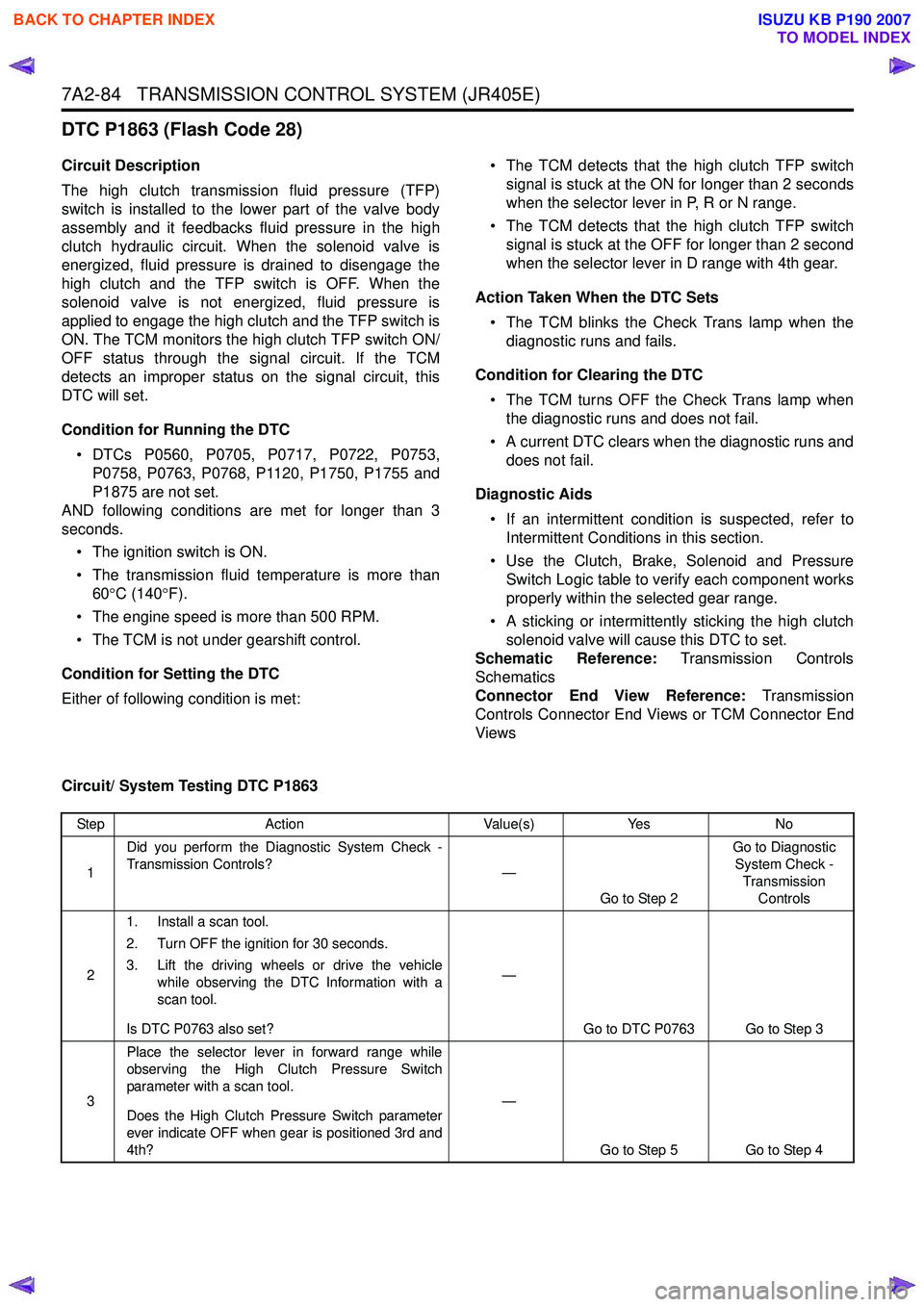
DTC P1863 (Flash Code 28)
Circuit Description
The high clutch transmission fluid pressure (TFP)
switch is installed to the lower part of the valve body
assembly and it feedbacks fluid pressure in the high
clutch hydraulic circuit. When the solenoid valve is
energized, fluid pressure is drained to disengage the
high clutch and the TFP switch is OFF. When the
solenoid valve is not energized, fluid pressure is
applied to engage the high clutch and the TFP switch is
ON. The TCM monitors the high clutch TFP switch ON/
OFF status through the signal circuit. If the TCM
detects an improper status on the signal circuit, this
DTC will set.
Condition for Running the DTC • DTCs P0560, P0705, P0717, P0722, P0753, P0758, P0763, P0768, P1120, P1750, P1755 and
P1875 are not set.
AND following conditions are met for longer than 3
seconds.
• The ignition switch is ON.
• The transmission fluid temperature is more than 60 °C (140 °F).
• The engine speed is more than 500 RPM.
• The TCM is not under gearshift control.
Condition for Setting the DTC
Either of following condition is met: • The TCM detects that the high clutch TFP switch
signal is stuck at the ON for longer than 2 seconds
when the selector lever in P, R or N range.
• The TCM detects that the high clutch TFP switch signal is stuck at the OFF for longer than 2 second
when the selector lever in D range with 4th gear.
Action Taken When the DTC Sets • The TCM blinks the Check Trans lamp when the diagnostic runs and fails.
Condition for Clearing the DTC • The TCM turns OFF the Check Trans lamp when the diagnostic runs and does not fail.
• A current DTC clears when the diagnostic runs and does not fail.
Diagnostic Aids • If an intermittent condition is suspected, refer to Intermittent Conditions in this section.
• Use the Clutch, Brake, Solenoid and Pressure Switch Logic table to verify each component works
properly within the selected gear range.
• A sticking or intermittently sticking the high clutch solenoid valve will cause this DTC to set.
Schematic Reference: Transmission Controls
Schematics
Connector End View Reference: Transmission
Controls Connector End Views or TCM Connector End
Views
Circuit/ System Testing DTC P1863
Step Action Value(s)Yes No
1 Did you perform the Diagnostic System Check -
Transmission Controls? —
Go to Step 2 Go to Diagnostic
System Check - Transmission Controls
2 1. Install a scan tool.
2. Turn OFF the ignition for 30 seconds.
3. Lift the driving wheels or drive the vehicle while observing the DTC Information with a
scan tool.
Is DTC P0763 also set? —
Go to DTC P0763 Go to Step 3
3 Place the selector lever in forward range while
observing the High Clutch Pressure Switch
parameter with a scan tool.
Does the High Clutch Pressure Switch parameter
ever indicate OFF when gear is positioned 3rd and
4th? —
Go to Step 5 Go to Step 4
BACK TO CHAPTER INDEX
TO MODEL INDEX
ISUZU KB P190 2007
Page 4405 of 6020
TRANSMISSION CONTROL SYSTEM (JR405E) 7A2-121
Test Instructions
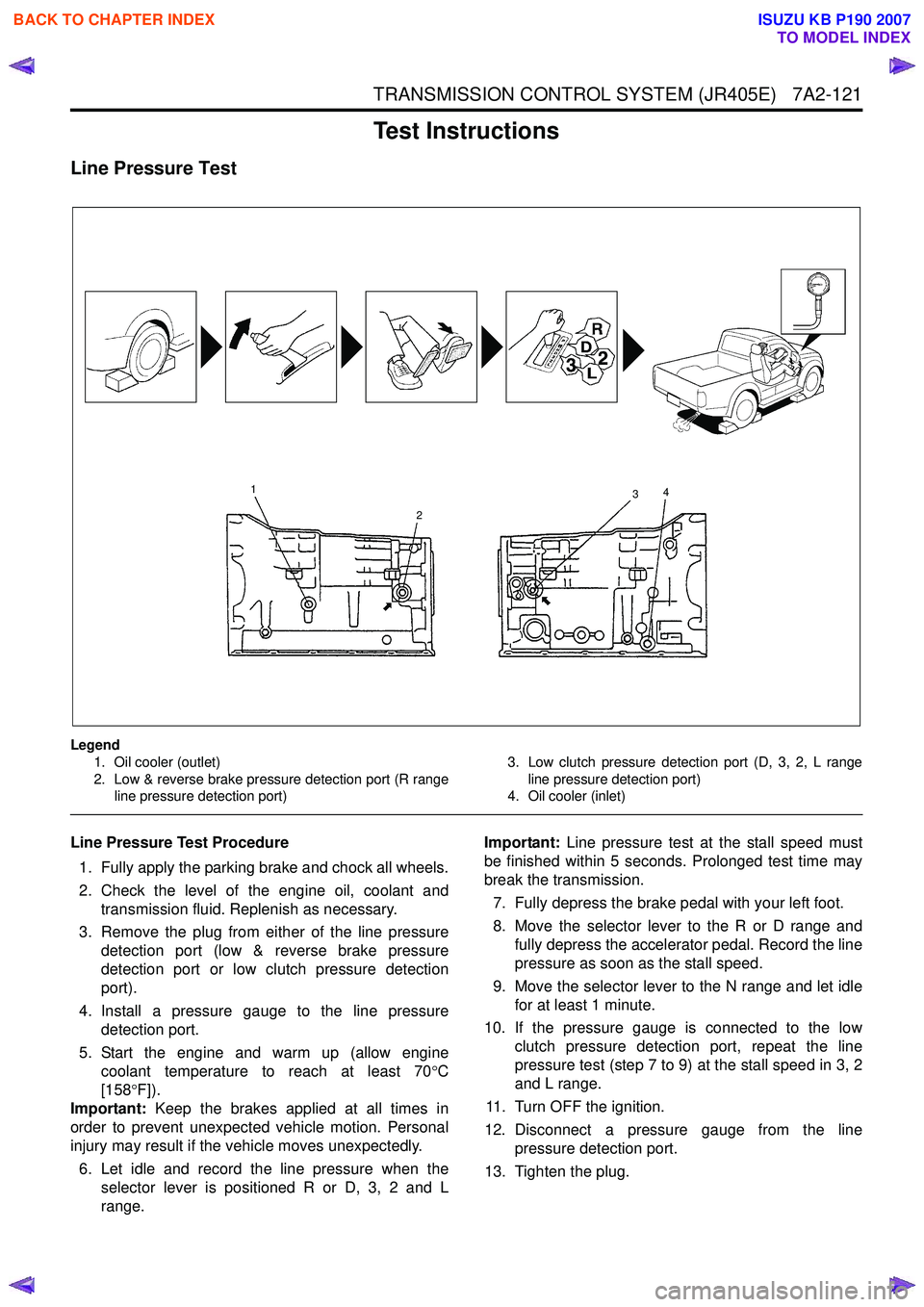
Line Pressure Test
Legend1. Oil cooler (outlet)
2. Low & reverse brake pressure detection port (R range line pressure detection port) 3. Low clutch pressure detection port (D, 3, 2, L range
line pressure detection port)
4. Oil cooler (inlet)
Line Pressure Test Procedure
1. Fully apply the parking brake and chock all wheels.
2. Check the level of the engine oil, coolant and transmission fluid. Replenish as necessary.
3. Remove the plug from either of the line pressure detection port (low & reverse brake pressure
detection port or low clutch pressure detection
port).
4. Install a pressure gauge to the line pressure detection port.
5. Start the engine and warm up (allow engine coolant temperature to reach at least 70 °C
[158 °F]).
Important: Keep the brakes applied at all times in
order to prevent unexpected vehicle motion. Personal
injury may result if the vehicle moves unexpectedly.
6. Let idle and record the line pressure when the selector lever is positioned R or D, 3, 2 and L
range. Important:
Line pressure test at the stall speed must
be finished within 5 seconds. Prolonged test time may
break the transmission.
7. Fully depress the brake pedal with your left foot.
8. Move the selector lever to the R or D range and fully depress the accelerator pedal. Record the line
pressure as soon as the stall speed.
9. Move the selector lever to the N range and let idle for at least 1 minute.
10. If the pressure gauge is connected to the low clutch pressure detection port, repeat the line
pressure test (step 7 to 9) at the stall speed in 3, 2
and L range.
11. Turn OFF the ignition.
12. Disconnect a pressure gauge from the line pressure detection port.
13. Tighten the plug.
1
2 3
4
BACK TO CHAPTER INDEX
TO MODEL INDEX
ISUZU KB P190 2007
Page 4407 of 6020
TRANSMISSION CONTROL SYSTEM (JR405E) 7A2-123
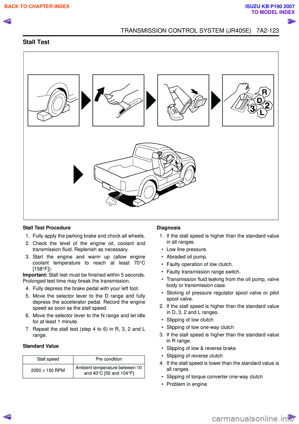
Stall Test
Stall Test Procedure1. Fully apply the parking brake and chock all wheels.
2. Check the level of the engine oil, coolant and transmission fluid. Replenish as necessary.
3. Start the engine and warm up (allow engine coolant temperature to reach at least 70 °C
[158 °F]).
Important: Stall test must be finished within 5 seconds.
Prolonged test time may break the transmission.
4. Fully depress the brake pedal with your left foot.
5. Move the selector lever to the D range and fully depress the accelerator pedal. Record the engine
speed as soon as the stall speed.
6. Move the selector lever to the N range and let idle for at least 1 minute.
7. Repeat the stall test (step 4 to 6) in R, 3, 2 and L range.
Standard Value Diagnosis
1. If the stall speed is higher than the standard value in all ranges.
• Low line pressure.
• Abraded oil pump.
• Faulty operation of low clutch.
• Faulty transmission range switch.
• Transmission fluid leaking from the oil pump, valve body or transmission case.
• Sticking of pressure regulator spool valve or pilot spool valve.
2. If the stall speed is higher than the standard value in D, 3, 2 and L ranges.
• Slipping of low clutch
• Slipping of low one-way clutch
3. If the stall speed is higher than the standard value in R range.
• Slipping of low & reverse brake
• Slipping of reverse clutch
4. If the stall speed is lower than the standard value is all ranges.
• Slipping of torque converter one-way clutch
• Problem in engine
Stall speed Pre condition
2050 ± 150 RPM Ambient temperature between 10
and 40 °C [50 and 104 °F]
BACK TO CHAPTER INDEX
TO MODEL INDEX
ISUZU KB P190 2007
Page 4408 of 6020
7A2-124 TRANSMISSION CONTROL SYSTEM (JR405E)
Time Lag Test
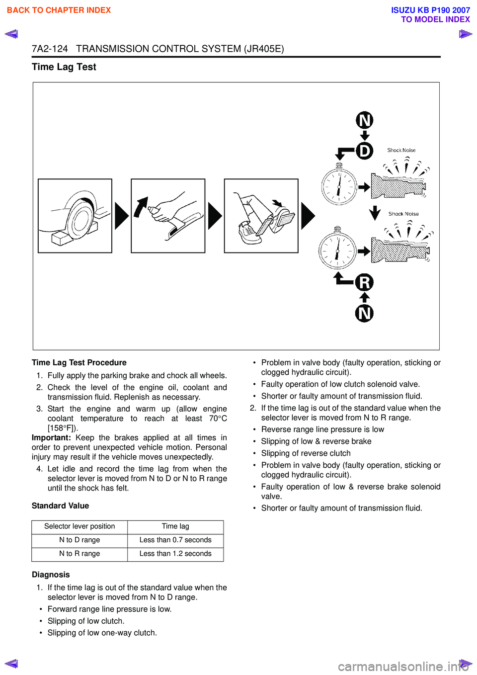
Time Lag Test Procedure1. Fully apply the parking brake and chock all wheels.
2. Check the level of the engine oil, coolant and transmission fluid. Replenish as necessary.
3. Start the engine and warm up (allow engine coolant temperature to reach at least 70 °C
[158 °F]).
Important: Keep the brakes applied at all times in
order to prevent unexpected vehicle motion. Personal
injury may result if the vehicle moves unexpectedly.
4. Let idle and record the time lag from when the selector lever is moved from N to D or N to R range
until the shock has felt.
Standard Value
Diagnosis 1. If the time lag is out of the standard value when the selector lever is moved from N to D range.
• Forward range line pressure is low.
• Slipping of low clutch.
• Slipping of low one-way clutch. • Problem in valve body (faulty operation, sticking or
clogged hydraulic circuit).
• Faulty operation of low clutch solenoid valve.
• Shorter or faulty amount of transmission fluid.
2. If the time lag is out of the standard value when the selector lever is moved from N to R range.
• Reverse range line pressure is low
• Slipping of low & reverse brake
• Slipping of reverse clutch
• Problem in valve body (faulty operation, sticking or clogged hydraulic circuit).
• Faulty operation of low & reverse brake solenoid valve.
• Shorter or faulty amount of transmission fluid.
Selector lever position Time lag
N to D range Less than 0.7 seconds
N to R range Less than 1.2 seconds
BACK TO CHAPTER INDEX
TO MODEL INDEX
ISUZU KB P190 2007
Page 4457 of 6020
ON-VEHICLE SERVICE (JR405E) 7A3-3
Cold Level
The vehicle must not have been driven so that the
temperature reaches around 20 °C (68 °F) before the
cold level check is made.
1. Park the vehicle on a level surface.
2. Apply the parking brake firmly.
3. Start the engine and allow it to warm up.
The engine coolant temperature gauge needle should be midway between the “C” mark and “H”
mark.
4. Let the engine run at idle.
Move the select lever slowly through all the gea
r
ranges.
Stop in each range just long enough for the transmission to engage.
5. Return the select lever either “P” or “N”.
6. Remove the ATF level dipstick.
7. W ipe the dipstick clean with a paper towel.
8. Reinsert the dipstick and wait several seconds.
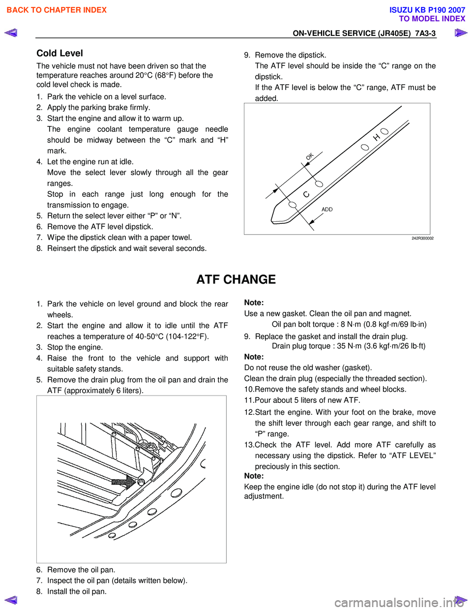
9. Remove the dipstick.
The ATF level should be inside the “C” range on the dipstick.
If the ATF level is below the “C” range, ATF must be added.
242R300002
ATF CHANGE
1. Park the vehicle on level ground and block the rear
wheels.
2. Start the engine and allow it to idle until the ATF reaches a temperature of 40-50 °C (104-122 °F).
3. Stop the engine.
4. Raise the front to the vehicle and support with suitable safety stands.
5. Remove the drain plug from the oil pan and drain the ATF (approximately 6 liters).
6. Remove the oil pan.
7. Inspect the oil pan (details written below).
8. Install the oil pan.
Note:
Use a new gasket. Clean the oil pan and magnet.
Oil pan bolt torque : 8 N ⋅m (0.8 kgf ⋅m/69 lb ⋅in)
9. Replace the gasket and install the drain plug.
Drain plug torque : 35 N ⋅m (3.6 kgf ⋅m/26 lb ⋅ft)
Note:
Do not reuse the old washer (gasket).
Clean the drain plug (especially the threaded section).
10.Remove the safety stands and wheel blocks.
11.Pour about 5 liters of new ATF.
12. Start the engine. W ith your foot on the brake, move the shift lever through each gear range, and shift to
“P” range.
13.Check the ATF level. Add more ATF carefully as necessary using the dipstick. Refer to “ATF LEVEL”
preciously in this section.
Note:
Keep the engine idle (do not stop it) during the ATF level
adjustment.
BACK TO CHAPTER INDEX
TO MODEL INDEX
ISUZU KB P190 2007
Page 4460 of 6020
7A3-6 ON-VEHICLE SERVICE (JR405E)
INHIBITOR SWITCH
The inhibitor switch is attached to the right side of the
transmission.
Inspect
1. Block the wheels.
2. Disconnect the negative battery cable.
3. Disconnect the harness connectors.
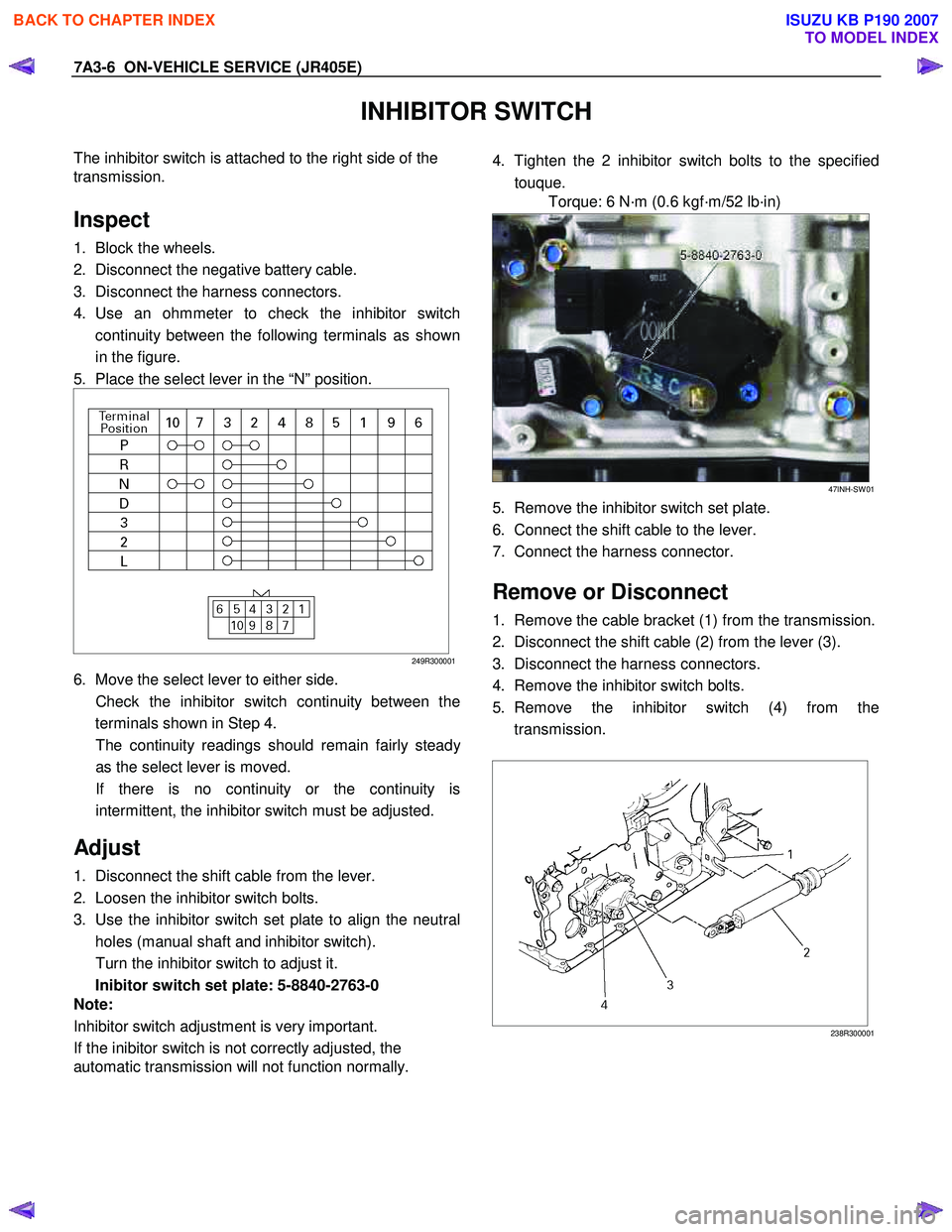
4. Use an ohmmeter to check the inhibitor switch continuity between the following terminals as shown
in the figure.
5. Place the select lever in the “N” position.
249R300001
6. Move the select lever to either side.
Check the inhibitor switch continuity between the terminals shown in Step 4.
The continuity readings should remain fairly stead
y
as the select lever is moved.
If there is no continuity or the continuity is intermittent, the inhibitor switch must be adjusted.
Adjust
1. Disconnect the shift cable from the lever.
2. Loosen the inhibitor switch bolts.
3. Use the inhibitor switch set plate to align the neutral holes (manual shaft and inhibitor switch).
Turn the inhibitor switch to adjust it.
Inibitor switch set plate: 5-8840-2763-0
Note:
Inhibitor switch adjustment is very important.
If the inibitor switch is not correctly adjusted, the
automatic transmission will not function normally.
4. Tighten the 2 inhibitor switch bolts to the specified
touque.
Torque: 6 N·m (0.6 kgf·m/52 lb·in)
47INH-SW 01
5. Remove the inhibitor switch set plate.
6. Connect the shift cable to the lever.
7. Connect the harness connector.
Remove or Disconnect
1. Remove the cable bracket (1) from the transmission.
2. Disconnect the shift cable (2) from the lever (3).
3. Disconnect the harness connectors.
4. Remove the inhibitor switch bolts.
5. Remove the inhibitor switch (4) from the transmission.
238R300001
BACK TO CHAPTER INDEX
TO MODEL INDEX
ISUZU KB P190 2007
Page 4461 of 6020
ON-VEHICLE SERVICE (JR405E) 7A3-7
Install or Connect
1. Install the inhibitor switch to the transmission.
Temporarily tighten the inhibitor switch bolts.
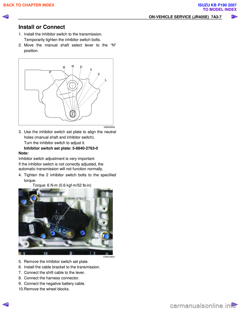
2. Move the manual shaft select lever to the “N” position.
249R300002
3. Use the inhibitor switch set plate to align the neutral
holes (manual shaft and inhibitor switch).
Turn the inhibitor switch to adjust it.
Inhibitor switch set plate: 5-8840-2763-0
Note:
Inhibitor switch adjustment is very important.
If the inhibitor switch is not correctly adjusted, the
automatic transmission will not function normally.
4. Tighten the 2 inhibitor switch bolts to the specified torque.
Torque: 6 N·m (0.6 kgf·m/52 lb·in)
47INH-SW 01
5. Remove the inhibitor switch set plate.
6. Install the cable bracket to the transmission.
7. Connect the shift cable to the lever.
8. Connect the harness connector.
9. Connect the negative battery cable.
10. Remove the wheel blocks.
BACK TO CHAPTER INDEX
TO MODEL INDEX
ISUZU KB P190 2007