2007 ISUZU KB P190 wheel
[x] Cancel search: wheelPage 4016 of 6020
7A2-50 TRANSMISSION CONTROL SYSTEM (AW30–40LE)
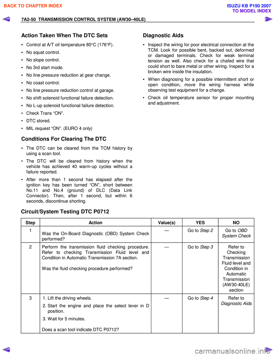
Action Taken When The DTC Sets
• Control at A/T oil temperature 80 °C (176 °F).
• No squat control.
• No slope control.
• No 3rd start mode.
• No line pressure reduction at gear change.
• No coast control.
• No line pressure reduction control at garage.
• No shift solenoid functional failure detection.
• No L-up solenoid functional failure detection.
• Check Trans “ON”.
• DTC stored.
• MIL request “ON”. (EURO 4 only)
Conditions For Clearing The DTC
• The DTC can be cleared from the TCM history by
using a scan tool.
• The DTC will be cleared from history when the vehicle has achieved 40 warm-up cycles without a
failure reported.
•
After more than 1 second has elapsed after the
ignition key has been turned “ON”, short between
No.11 and No.4 (ground) of DLC (Data Link
Connector). Then, after 1 second, but within 6
seconds, discontinue shorting.
Diagnostic Aids
•
Inspect the wiring for poor electrical connection at the
TCM. Look for possible bent, backed out, deformed
or damaged terminals. Check for weak terminal
tension as well. Also check for a chafed wire that
could short to bare metal or other wiring. Inspect for a
broken wire inside the insulation.
• W hen diagnosing for a possible intermittent short o
r
open condition, move the wiring harness while
observing test equipment for a change.
• Check oil temperature sensor for proper mounting and adjustment.
Circuit/System Testing DTC P0712
Step Action Value(s) YES NO
1
W as the On-Board Diagnostic (OBD) System Check
performed? — Go to
Step 2 Go to OBD
System Check
2 Perform the transmission fluid checking procedure. Refer to checking Transmission Fluid level and
Condition in Automatic Transmission 7A section.
W as the fluid checking procedure performed? — Go to
Step 3 Refer to
Checking
Transmission
Fluid level and Condition in Automatic
Transmission
(AW 30-40LE) section
3 1. Lift the driving wheels.
2. Start the engine and place the select lever in D
position.
3. W ait for 5 minutes.
Does a scan tool indicate DTC P0712? — Go to
Step 4 Refer to
Diagnostic Aids
BACK TO CHAPTER INDEX
TO MODEL INDEX
ISUZU KB P190 2007
Page 4019 of 6020
TRANSMISSION CONTROL SYSTEM (AW30–40LE) 7A2-53
• No L-up solenoid functional failure detection.
• Check Trans “ON”.
• DTC stored.
• MIL request “ON”. (EURO 4 only)
Conditions For Clearing The DTC
• The DTC can be cleared from the TCM history by
using a scan tool.
• The DTC will be cleared from history when the
vehicle has achieved 40 warm-up cycles without a
failure reported.
•
After more than 1 second has elapsed after the
ignition key has been turned “ON”, short between
No.11 and No.4 (ground) of DLC (Data Link
Connector). Then, after 1 second, but within 6
seconds, discontinue shorting.
Diagnostic Aids
•
Inspect the wiring for poor electrical connection at the
TCM. Look for possible bent, backed out, deformed
or damaged terminals. Check for weak terminal
tension as well. Also check for a chafed wire that
could short to bare metal or other wiring. Inspect for a
broken wire inside the insulation.
• W hen diagnosing for a possible intermittent short o
r
open condition, move the wiring harness while
observing test equipment for a change.
• Check oil temperature sensor for proper mounting
and adjustment.
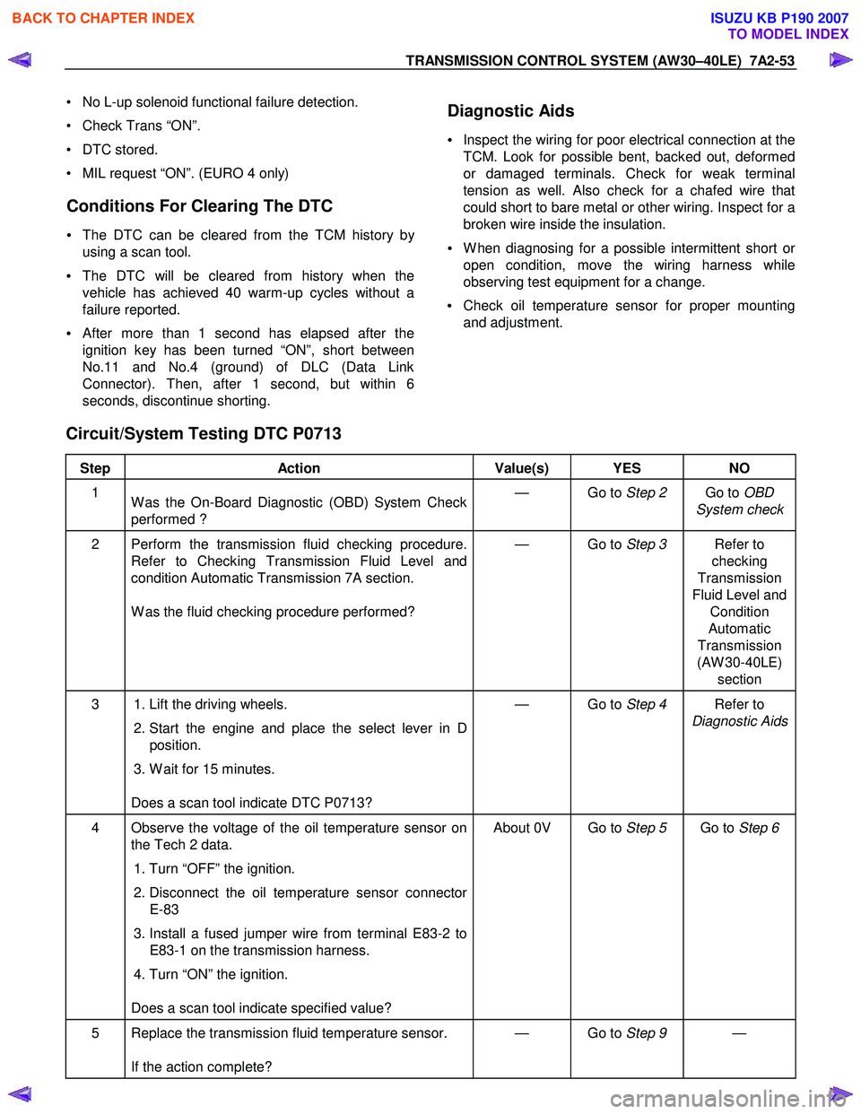
Circuit/System Testing DTC P0713
Step Action Value(s) YES NO
1
W as the On-Board Diagnostic (OBD) System Check
performed ? — Go to
Step 2 Go to OBD
System check
2 Perform the transmission fluid checking procedure. Refer to Checking Transmission Fluid Level and
condition Automatic Transmission 7A section.
W as the fluid checking procedure performed? — Go to
Step 3 Refer to
checking
Transmission
Fluid Level and Condition
Automatic
Transmission
(AW 30-40LE) section
3 1. Lift the driving wheels.
2. Start the engine and place the select lever in D
position.
3. W ait for 15 minutes.
Does a scan tool indicate DTC P0713? — Go to
Step 4 Refer to
Diagnostic Aids
4 Observe the voltage of the oil temperature sensor on the Tech 2 data.
1. Turn “OFF” the ignition.
2. Disconnect the oil temperature sensor connector
E-83
3. Install a fused jumper wire from terminal E83-2 to E83-1 on the transmission harness.
4. Turn “ON” the ignition.
Does a scan tool indicate specified value? About 0V Go to
Step 5 Go to Step 6
5 Replace the transmission fluid temperature sensor.
If the action complete? — Go to
Step 9 —
BACK TO CHAPTER INDEX
TO MODEL INDEX
ISUZU KB P190 2007
Page 4027 of 6020
TRANSMISSION CONTROL SYSTEM (AW30–40LE) 7A2-61
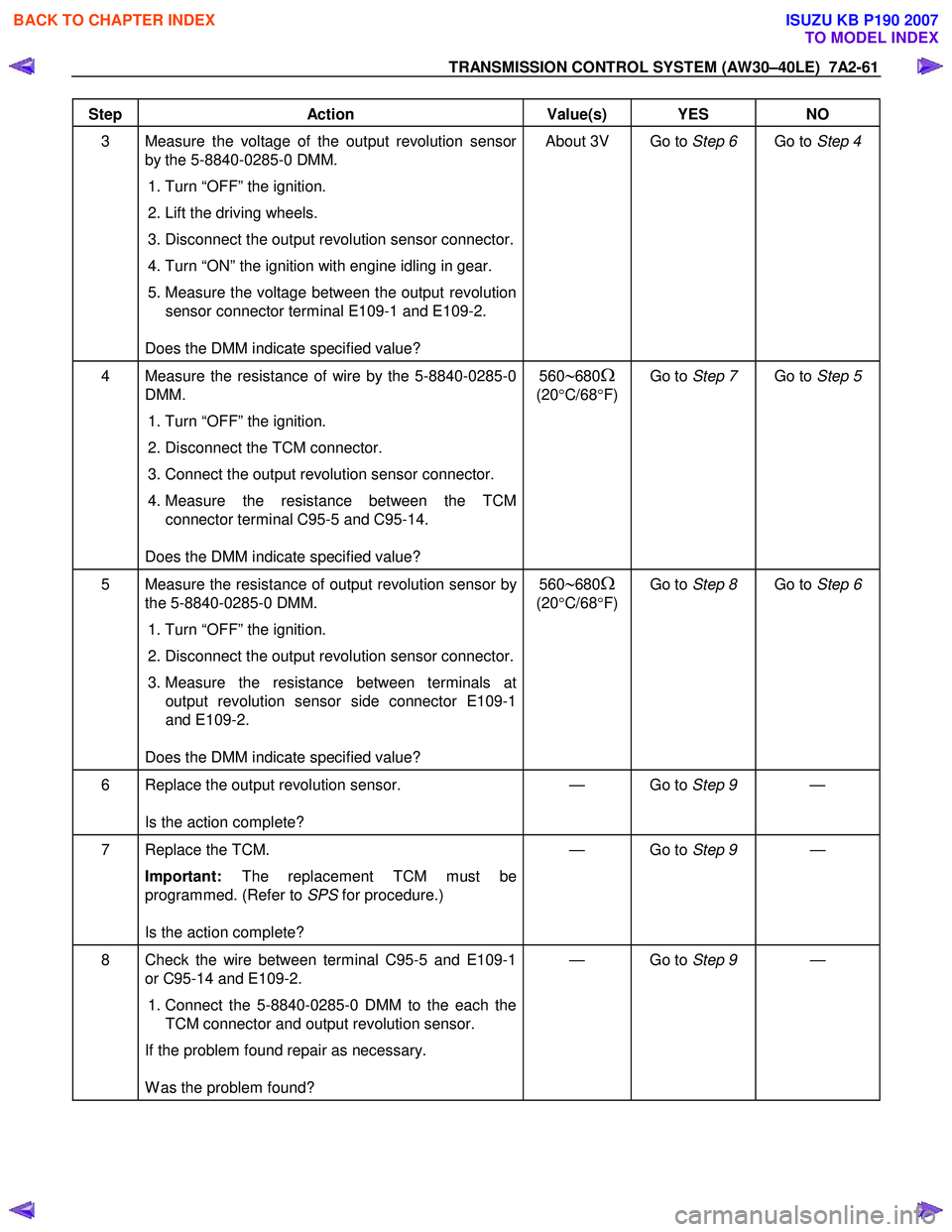
Step Action Value(s) YES NO
3 Measure the voltage of the output revolution sensor
by the 5-8840-0285-0 DMM.
1. Turn “OFF” the ignition.
2. Lift the driving wheels.
3. Disconnect the output revolution sensor connector.
4. Turn “ON” the ignition with engine idling in gear.
5. Measure the voltage between the output revolution sensor connector terminal E109-1 and E109-2.
Does the DMM indicate specified value? About 3V Go to
Step 6 Go to Step 4
4 Measure the resistance of wire by the 5-8840-0285-0
DMM.
1. Turn “OFF” the ignition.
2. Disconnect the TCM connector.
3. Connect the output revolution sensor connector.
4. Measure the resistance between the TCM
connector terminal C95-5 and C95-14.
Does the DMM indicate specified value? 560∼680Ω
(20
°C/68 °F) Go to
Step 7 Go to Step 5
5 Measure the resistance of output revolution sensor by
the 5-8840-0285-0 DMM.
1. Turn “OFF” the ignition.
2. Disconnect the output revolution sensor connector.
3. Measure the resistance between terminals at
output revolution sensor side connector E109-1
and E109-2.
Does the DMM indicate specified value? 560∼680Ω
(20
°C/68 °F) Go to
Step 8 Go to Step 6
6 Replace the output revolution sensor.
Is the action complete? — Go to
Step 9 —
7 Replace the TCM.
Important: The replacement TCM must be
programmed. (Refer to SPS for procedure.)
Is the action complete? — Go to
Step 9 —
8 Check the wire between terminal C95-5 and E109-1
or C95-14 and E109-2.
1. Connect the 5-8840-0285-0 DMM to the each the
TCM connector and output revolution sensor.
If the problem found repair as necessary.
W as the problem found? — Go to
Step 9 —
BACK TO CHAPTER INDEX
TO MODEL INDEX
ISUZU KB P190 2007
Page 4095 of 6020
7A3-10 ON-VEHICLE SERVICE (AW30–40LE)
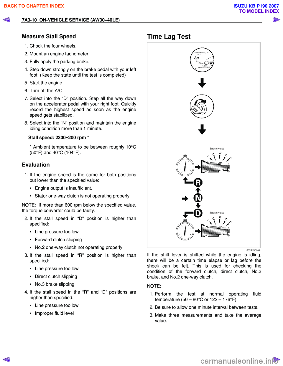
Measure Stall Speed
1. Chock the four wheels.
2. Mount an engine tachometer.
3. Fully apply the parking brake.
4. Step down strongly on the brake pedal with your left foot. (Keep the state until the test is completed)
5. Start the engine.
6. Turn off the A/C.
7. Select into the “D" position. Step all the way down on the accelerator pedal with your right foot. Quickl
y
record the highest speed as soon as the engine
speed gets stabilized.
8. Select into the “N” position and maintain the engine
idling condition more than 1 minute.
Stall speed: 2300 ±
±±
±
200 rpm *
* Ambient temperature to be between roughly 10 °C
(50 °F) and 40 °C (104 °F).
Evaluation
1. If the engine speed is the same for both positions
but lower than the specified value:
• Engine output is insufficient.
• Stator one-way clutch is not operating properly.
NOTE: If more than 600 rpm below the specified value,
the torque converter could be faulty.
2. If the stall speed in “D" position is higher than
specified:
• Line pressure too low
• Forward clutch slipping
• No.2 one-way clutch not operating properly
3. If the stall speed in “R" position is higher than
specified:
• Line pressure too low
• Direct clutch slipping
• No.3 brake slipping
4. If the stall speed in the “R" and “D" positions are
higher than specified:
• Line pressure too low
• Improper fluid level
Time Lag Test
F07RY00003
If the shift lever is shifted while the engine is idling,
there will be a certain time elapse or lag before the
shock can be felt. This is used for checking the
condition of the forward clutch, direct clutch, No.3
brake, and No.2 one-way clutch.
NOTE:
1. Perform the test at normal operating fluid
temperature (50 – 80 °C or 122 – 176 °F)
2. Be sure to allow one minute interval between tests.
3. Make three measurements and take the average value.
BACK TO CHAPTER INDEX
TO MODEL INDEX
ISUZU KB P190 2007
Page 4097 of 6020
7A3-12 ON-VEHICLE SERVICE (AW30–40LE)
Measure Line Pressure
1. Fully apply the parking brake and chock the four
wheels.
2. Start the engine and check idling rpm.
3. Select into “D" position, step down strongly on the brake pedal with your left foot and while
manipulating the accelerator pedal with the right
foot, measure the line pressures at the engine
speeds specified in the table.
4. In the same manner, perform the test in “R" position.
Line pressure kPa (kg/cm
2/psi) Engine
speed “D" position “R" position
Idling 349 – 408
(3.6 – 4.2 /51 – 59) 577 – 675
(5.9 – 6.9/84 – 98)
Stall 1,206 – 1,353
(12.3–13.8/175–196) 1,646 – 1,979
(16.8–20.2/239–287)
Evaluation
1. If the measured values at all positions are higher
than specified:
• Pressure control solenoid defective
• Primary regulator valve defective
2. If the measured values at all positions are lowe
r
than specified:
• Primary regulator valve defective
• Oil pump defective
• Pressure control solenoid defective
3. If pressure is low in “D" position only:
• “D" position circuit fluid leakage
4. If pressure is low in “R" position only:
• “R" position circuit fluid leakage
Road Test
NOTE: Perform the test at normal operating fluid
temperature (50 – 80 °C or 122 – 176 °F).
“D" Position Test in “NORMAL", and
“POWER" Pattern
Select into the “D" position and hold the accelerator
pedal constant at the 50% and 100% throttle valve
opening positions.
Push in one of the pattern selector buttons and check
the following:
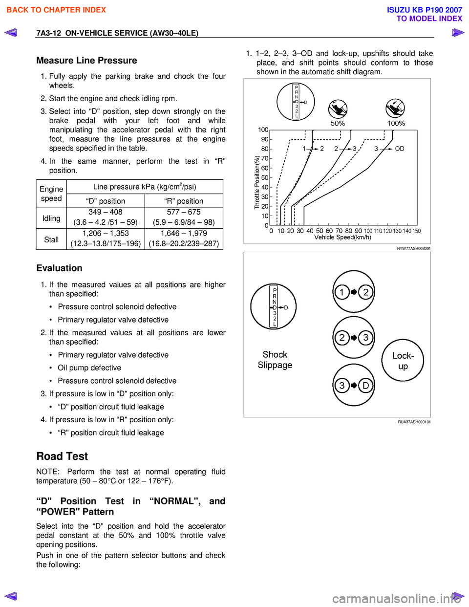
1. 1–2, 2–3, 3–OD and lock-up, upshifts should take
place, and shift points should conform to those
shown in the automatic shift diagram.
RTW 77ASH003001
RUA37ASH000101
BACK TO CHAPTER INDEX
TO MODEL INDEX
ISUZU KB P190 2007
Page 4107 of 6020
7A3-22 ON-VEHICLE SERVICE (AW30–40LE)
Input and Output Revolution Sensor
Inspection
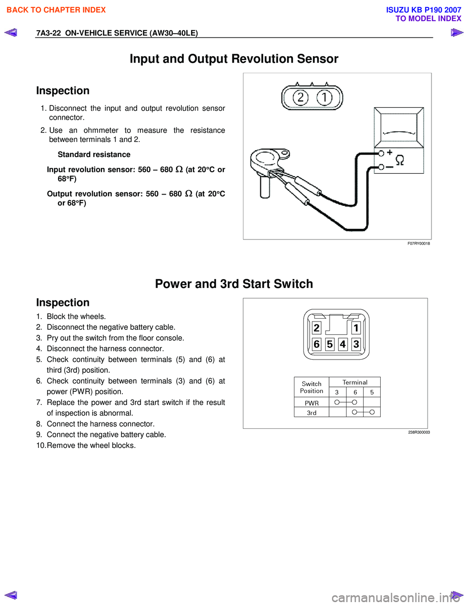
1. Disconnect the input and output revolution sensor
connector.
2. Use an ohmmeter to measure the resistance between terminals 1 and 2.
Standard resistance
Input revolution sensor: 560 – 680
Ω
ΩΩ
Ω (at 20
°
°°
°
Cor
68 °
°°
°
F)
Output revolution sensor: 560 – 680
Ω
ΩΩ
Ω (at 20
°
°°
°
C
or 68 °
°°
°
F)
F07RY00018
Power and 3rd Start Switch
Inspection
1. Block the wheels.
2. Disconnect the negative battery cable.
3. Pry out the switch from the floor console.
4. Disconnect the harness connector.
5. Check continuity between terminals (5) and (6) at third (3rd) position.
6. Check continuity between terminals (3) and (6) at power (PW R) position.
7. Replace the power and 3rd start switch if the result of inspection is abnormal.
8. Connect the harness connector.
9. Connect the negative battery cable.
10. Remove the wheel blocks.
238R300003
BACK TO CHAPTER INDEX
TO MODEL INDEX
ISUZU KB P190 2007
Page 4111 of 6020
7A3-26 ON-VEHICLE SERVICE (AW30–40LE)
Remove or Disconnect
1. Block the wheels.
2. Disconnect the negative battery cable.
3. Remove the rear console and the front console.
4. Remove the 2 screws fixing the select lever knob.
5. Remove the knob together with the knob button and spring from the lever.
6. Turn the sleeve counterclockwise to remove it. Make a note of the number of turns required to free
the sleeve.
7. Remove the harness connectors from the base plate.
8. Remove the upper housing (held in place by 4 latched fasteners).
9. Remove the lamp assembly by turning it counterclockwise.
10. Remove the spring plate.
11. Remove the grooved pin.
12. Disconnect the shift cable from the select lever.
13. Remove the lever assembly by pressing the rod down (lever in N position).
14. Remove the harness connectors from the shift lock unit, then remove the shift lock unit.
15. Remove the interlock controller.
16. If the replacement of shift lock release button o
r
shift lock button spring is required, remove the
position indicator housing, the shift lock button
spring and shift lock release button can be
removed.
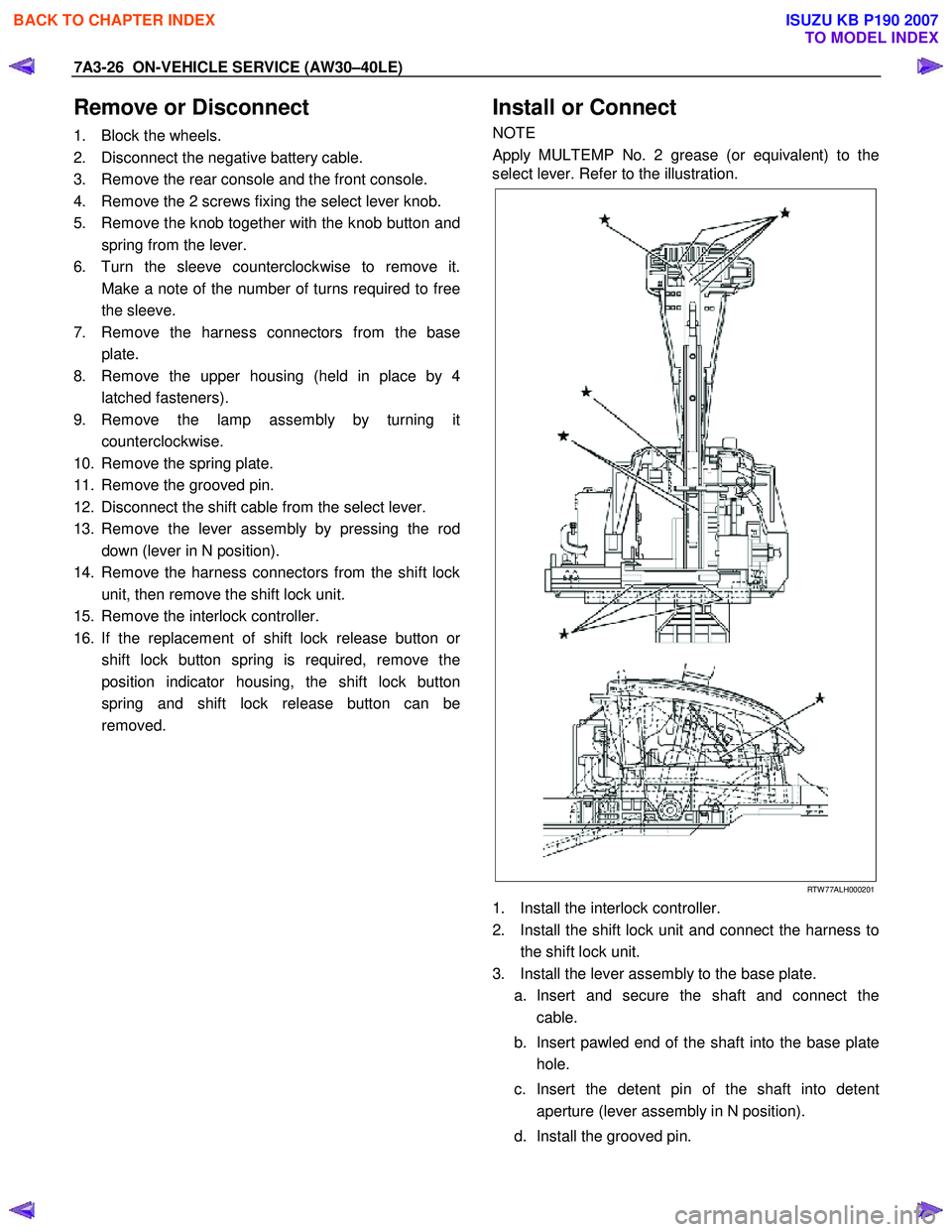
Install or Connect
NOTE
Apply MULTEMP No. 2 grease (or equivalent) to the
select lever. Refer to the illustration.
RTW 77ALH000201
1. Install the interlock controller.
2. Install the shift lock unit and connect the harness to the shift lock unit.
3. Install the lever assembly to the base plate. a. Insert and secure the shaft and connect the cable.
b. Insert pawled end of the shaft into the base plate hole.
c. Insert the detent pin of the shaft into detent aperture (lever assembly in N position).
d. Install the grooved pin.
BACK TO CHAPTER INDEX
TO MODEL INDEX
ISUZU KB P190 2007
Page 4113 of 6020
7A3-28 ON-VEHICLE SERVICE (AW30–40LE)
Shift Cable
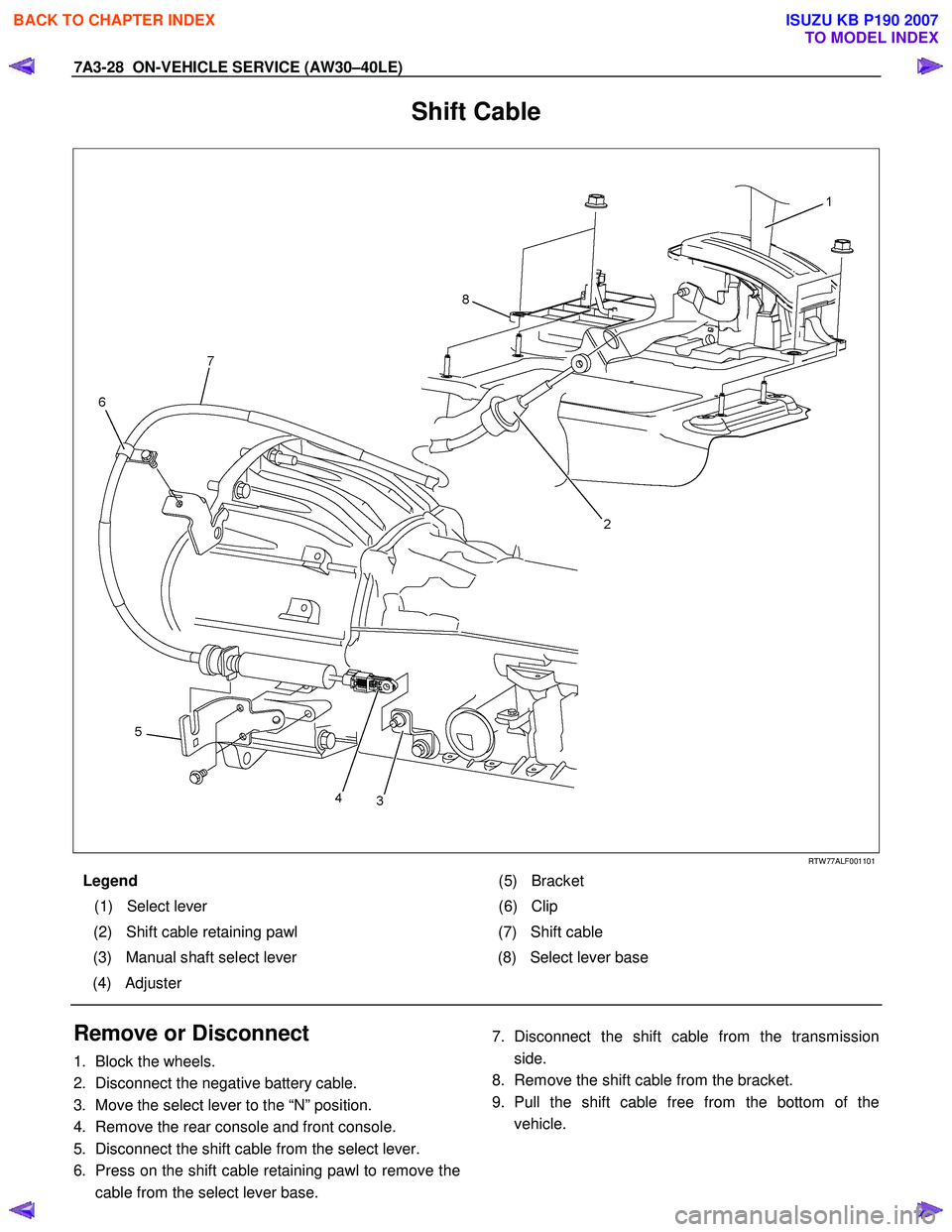
RTW 77ALF001101
Legend (5) Bracket
(1) Select lever (6) Clip
(2) Shift cable retaining pawl (7) Shift cable
(3) Manual shaft select lever (8) Select lever base
(4) Adjuster
Remove or Disconnect
1. Block the wheels.
2. Disconnect the negative battery cable.
3. Move the select lever to the “N” position.
4. Remove the rear console and front console.
5. Disconnect the shift cable from the select lever.
6. Press on the shift cable retaining pawl to remove the
cable from the select lever base.
7. Disconnect the shift cable from the transmission
side.
8. Remove the shift cable from the bracket.
9. Pull the shift cable free from the bottom of the
vehicle.
BACK TO CHAPTER INDEX
TO MODEL INDEX
ISUZU KB P190 2007