2007 ISUZU KB P190 wheel
[x] Cancel search: wheelPage 3800 of 6020
Automatic Transmission – 4L60E – Electrical Diagnosis Page 7C2–14
3 Tech 2 Information
3.1 Tech 2 Diagnostics
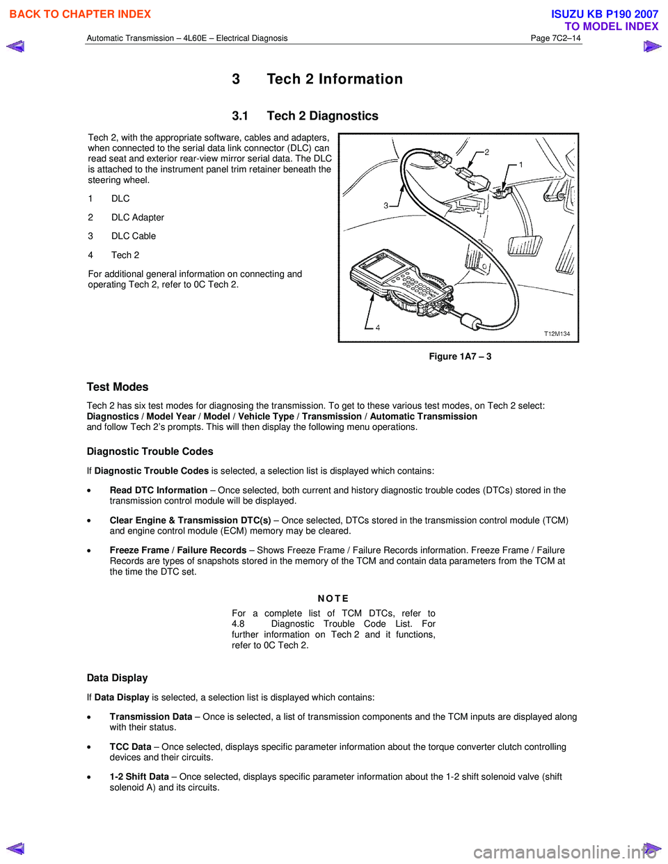
Tech 2, with the appropriate software, cables and adapters,
when connected to the serial data link connector (DLC) can
read seat and exterior rear-view mirror serial data. The DLC
is attached to the instrument panel trim retainer beneath the
steering wheel.
1 DLC
2 DLC Adapter
3 DLC Cable
4 Tech 2
For additional general information on connecting and
operating Tech 2, refer to 0C Tech 2.
Figure 1A7 – 3
Test Modes
Tech 2 has six test modes for diagnosing the transmission. To get to these various test modes, on Tech 2 select:
Diagnostics / Model Year / Model / Vehicle Type / Transmission / Automatic Transmission
and follow Tech 2’s prompts. This will then display the following menu operations.
Diagnostic Trouble Codes
If Diagnostic Trouble Codes is selected, a selection list is displayed which contains:
• Read DTC Information – Once selected, both current and history diagnostic trouble codes (DTCs) stored in the
transmission control module will be displayed.
• Clear Engine & Transmission DTC(s) – Once selected, DTCs stored in the transmission control module (TCM)
and engine control module (ECM) memory may be cleared.
• Freeze Frame / Failure Records – Shows Freeze Frame / Failure Records information. Freeze Frame / Failure
Records are types of snapshots stored in the memory of the TCM and contain data parameters from the TCM at
the time the DTC set.
NOTE
For a complete list of TCM DTCs, refer to
4.8 Diagnostic Trouble Code List. For
further information on Tech 2 and it functions,
refer to 0C Tech 2.
Data Display
If Data Display is selected, a selection list is displayed which contains:
• Transmission Data – Once is selected, a list of transmission components and the TCM inputs are displayed along
with their status.
• TCC Data – Once selected, displays specific parameter information about the torque converter clutch controlling
devices and their circuits.
• 1-2 Shift Data – Once selected, displays specific parameter information about the 1-2 shift solenoid valve (shift
solenoid A) and its circuits.
BACK TO CHAPTER INDEX
TO MODEL INDEX
ISUZU KB P190 2007
Page 3803 of 6020
Automatic Transmission – 4L60E – Electrical Diagnosis Page 7C2–17
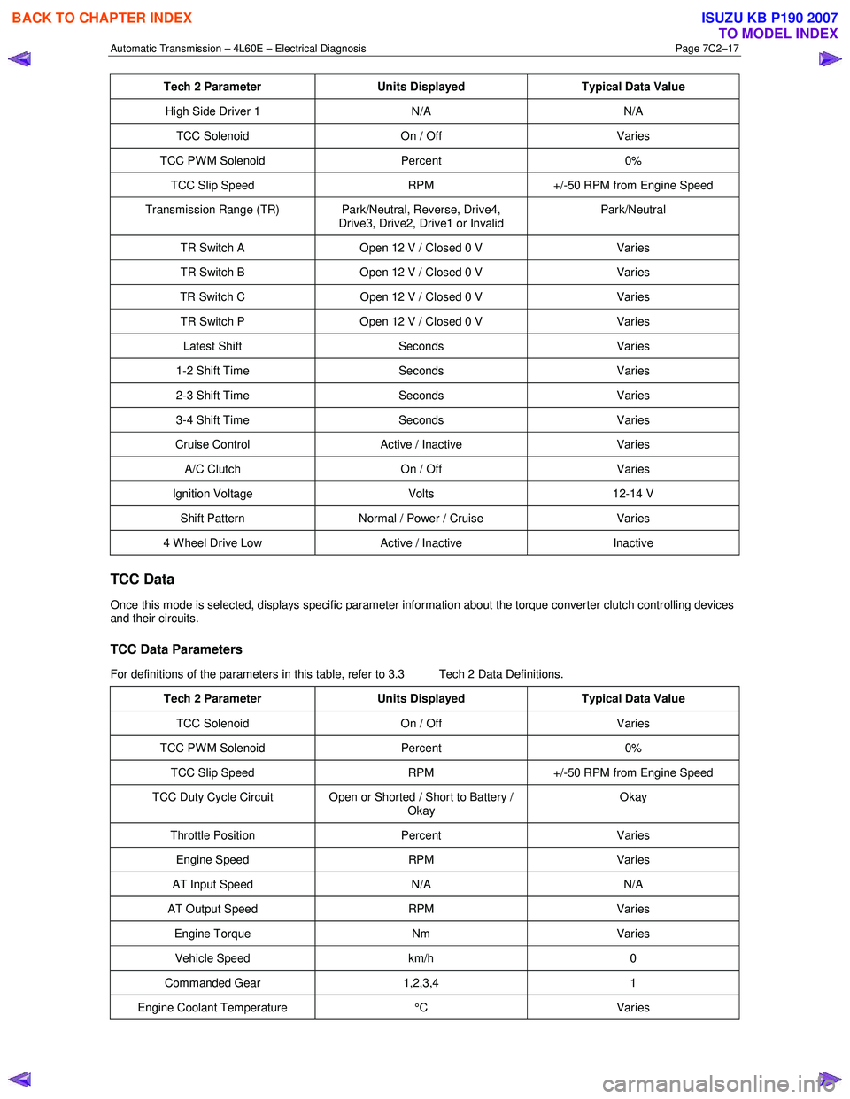
Tech 2 Parameter Units Displayed Typical Data Value
High Side Driver 1 N/A N/A
TCC Solenoid On / Off Varies
TCC PWM Solenoid Percent 0%
TCC Slip Speed RPM +/-50 RPM from Engine Speed
Transmission Range (TR) Park/Neutral, Reverse, Drive4,
Drive3, Drive2, Drive1 or Invalid Park/Neutral
TR Switch A
Open 12 V / Closed 0 V Varies
TR Switch B Open 12 V / Closed 0 V Varies
TR Switch C Open 12 V / Closed 0 V Varies
TR Switch P Open 12 V / Closed 0 V Varies
Latest Shift Seconds Varies
1-2 Shift Time Seconds Varies
2-3 Shift Time Seconds Varies
3-4 Shift Time Seconds Varies
Cruise Control Active / Inactive Varies
A/C Clutch On / Off Varies
Ignition Voltage Volts 12-14 V
Shift Pattern Normal / Power / Cruise Varies
4 Wheel Drive Low Active / Inactive Inactive
TCC Data
Once this mode is selected, displays specific parameter information about the torque converter clutch controlling devices
and their circuits.
TCC Data Parameters
For definitions of the parameters in this table, refer to 3.3 Tech 2 Data Definitions.
Tech 2 Parameter Units Displayed Typical Data Value
TCC Solenoid On / Off Varies
TCC PWM Solenoid Percent 0%
TCC Slip Speed RPM +/-50 RPM from Engine Speed
TCC Duty Cycle Circuit Open or Shorted / Short to Battery /
Okay Okay
Throttle Position
Percent Varies
Engine Speed RPM Varies
AT Input Speed N/A N/A
AT Output Speed RPM Varies
Engine Torque Nm Varies
Vehicle Speed km/h 0
Commanded Gear 1,2,3,4 1
Engine Coolant Temperature °C Varies
BACK TO CHAPTER INDEX
TO MODEL INDEX
ISUZU KB P190 2007
Page 3837 of 6020
Automatic Transmission – 4L60E – Electrical Diagnosis Page 7C2–51
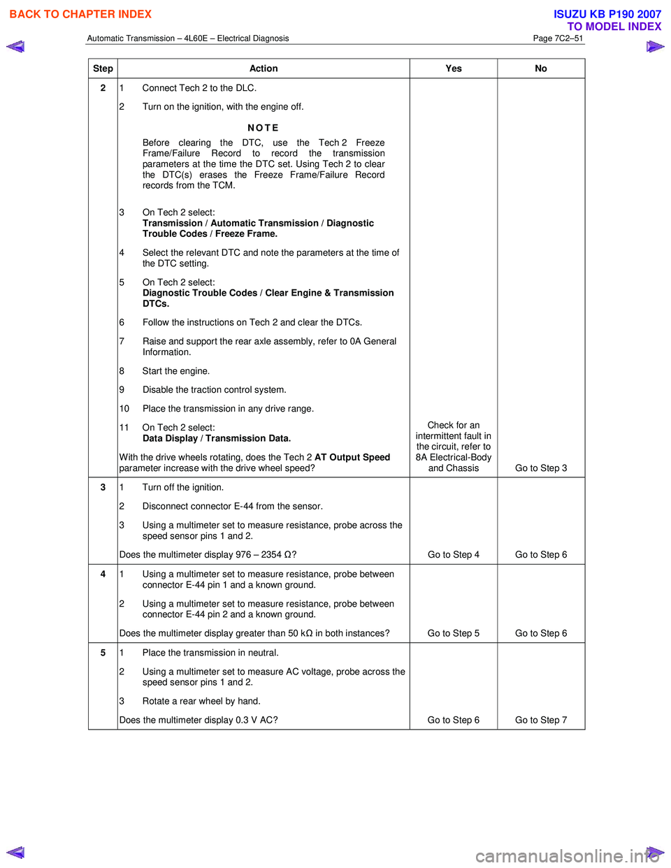
Step Action Yes No
2 1 Connect Tech 2 to the DLC.
2 Turn on the ignition, with the engine off.
NOTE
Before clearing the DTC, use the Tech 2 Freeze
Frame/Failure Record to record the transmission
parameters at the time the DTC set. Using Tech 2 to clear
the DTC(s) erases the Freeze Frame/Failure Record
records from the TCM.
3 On Tech 2 select: Transmission / Automatic Transmission / Diagnostic
Trouble Codes / Freeze Frame.
4 Select the relevant DTC and note the parameters at the time of the DTC setting.
5 On Tech 2 select:
Diagnostic Trouble Codes / Clear Engine & Transmission
DTCs.
6 Follow the instructions on Tech 2 and clear the DTCs.
7 Raise and support the rear axle assembly, refer to 0A General Information.
8 Start the engine.
9 Disable the traction control system.
10 Place the transmission in any drive range.
11 On Tech 2 select: Data Display / Transmission Data.
W ith the drive wheels rotating, does the Tech 2 AT Output Speed
parameter increase with the drive wheel speed? Check for an
intermittent fault in the circuit, refer to
8A Electrical-Body and Chassis Go to Step 3
3 1 Turn off the ignition.
2 Disconnect connector E-44 from the sensor.
3 Using a multimeter set to measure resistance, probe across the speed sensor pins 1 and 2.
Does the multimeter display 976 – 2354 Ω? Go to Step 4 Go to Step 6
4 1 Using a multimeter set to measure resistance, probe between
connector E-44 pin 1 and a known ground.
2 Using a multimeter set to measure resistance, probe between connector E-44 pin 2 and a known ground.
Does the multimeter display greater than 50 k Ω in both instances? Go to Step 5 Go to Step 6
5 1 Place the transmission in neutral.
2 Using a multimeter set to measure AC voltage, probe across the speed sensor pins 1 and 2.
3 Rotate a rear wheel by hand.
Does the multimeter display 0.3 V AC? Go to Step 6 Go to Step 7
BACK TO CHAPTER INDEX
TO MODEL INDEX
ISUZU KB P190 2007
Page 3840 of 6020
Automatic Transmission – 4L60E – Electrical Diagnosis Page 7C2–54
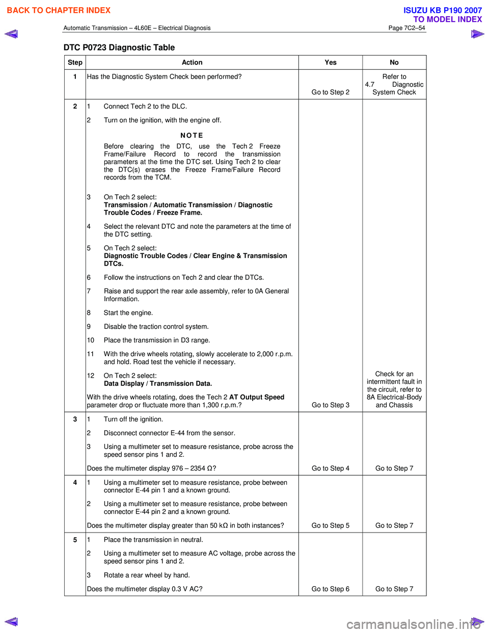
DTC P0723 Diagnostic Table
Step Action Yes No
1 Has the Diagnostic System Check been performed?
Go to Step 2 Refer to
4.7 Diagnostic System Check
2 1 Connect Tech 2 to the DLC.
2 Turn on the ignition, with the engine off.
NOTE
Before clearing the DTC, use the Tech 2 Freeze
Frame/Failure Record to record the transmission
parameters at the time the DTC set. Using Tech 2 to clear
the DTC(s) erases the Freeze Frame/Failure Record
records from the TCM.
3 On Tech 2 select: Transmission / Automatic Transmission / Diagnostic
Trouble Codes / Freeze Frame.
4 Select the relevant DTC and note the parameters at the time of the DTC setting.
5 On Tech 2 select:
Diagnostic Trouble Codes / Clear Engine & Transmission
DTCs.
6 Follow the instructions on Tech 2 and clear the DTCs.
7 Raise and support the rear axle assembly, refer to 0A General Information.
8 Start the engine.
9 Disable the traction control system.
10 Place the transmission in D3 range.
11 With the drive wheels rotating, slowly accelerate to 2,000 r.p.m. and hold. Road test the vehicle if necessary.
12 On Tech 2 select: Data Display / Transmission Data.
W ith the drive wheels rotating, does the Tech 2 AT Output Speed
parameter drop or fluctuate more than 1,300 r.p.m.? Go to Step 3 Check for an
intermittent fault in the circuit, refer to
8A Electrical-Body and Chassis
3 1 Turn off the ignition.
2 Disconnect connector E-44 from the sensor.
3 Using a multimeter set to measure resistance, probe across the speed sensor pins 1 and 2.
Does the multimeter display 976 – 2354 Ω? Go to Step 4 Go to Step 7
4 1 Using a multimeter set to measure resistance, probe between
connector E-44 pin 1 and a known ground.
2 Using a multimeter set to measure resistance, probe between connector E-44 pin 2 and a known ground.
Does the multimeter display greater than 50 k Ω in both instances? Go to Step 5 Go to Step 7
5 1 Place the transmission in neutral.
2 Using a multimeter set to measure AC voltage, probe across the speed sensor pins 1 and 2.
3 Rotate a rear wheel by hand.
Does the multimeter display 0.3 V AC? Go to Step 6 Go to Step 7
BACK TO CHAPTER INDEX
TO MODEL INDEX
ISUZU KB P190 2007
Page 3916 of 6020
Automatic Transmission – 4L60E – On-vehicle Servicing Page 7C4–3
1 General Information
This Section describes the removal and reinstallation procedures of the four speed 4L60E hydra-matic automatic
transmission as well as the service operations which can be performed with the transmission still fitted to the vehicle.
1.1 General Service Information
Description
The shift selector mechanism is linked to the transmission manual shaft with a selector cable. A heat protector is fitted
over the neutral start and back-up switch and manual shaft select lever.
For rear wheel drive (RWD) vehicles an extension housing is fitted to the rear of the transmission case.
Four wheel drive (4W D) vehicles have an adaptor housing and transfer case fitted to the rear of the transmission case,
for description and service operation refer to 7D Transfer Case and Adaptor Housing.
The four speed 4L60E hydra-matic automatic transmission is fitted with a filler tube, a breather hose and a vent pipe for
hot fluid overflow.
The transmission fluid is driven through a cooler within the radiator via the cooler line/hose assemblies to maintain
normal operating temperature.
Service Information
Throughout the service operations within this
Section, when handling retaining clips, using
compressed air or cleaning fluids, wear safety
equipment to avoid personal injury.
Refer to 7C1 Automatic Transmission – 4L60E – General Information for the following:
• information relating to mechanical and electrical operations,
• abbreviations, transmission specifications, special tools and torque wrench specifications,
• servicing, cleaning and inspection procedure recommendations.
It is essential to read and understand the General Information, W arnings, Cautions and Service Notes contained in that
same Section, before any service operation is performed on the four speed 4L60E hydra-matic automatic transmission or
any associated components.
Failure to comply with the procedures and service notes can affect the reliable and efficient operation of this automatic
transmission.
1.2 WARNINGS, CAUTIONS and NOTES
This Section contains various W ARNINGS, CAUTIONS and NOTE statements that you must observe carefully to reduce
the risk of death or injury during service, repair procedures or vehicle operation. Incorrect service or repair procedures
may damage the vehicle or cause operational faults. W ARNINGS, CAUTION and NOTE statements are not exhaustive.
GM HOLDEN LTD can not possibly warn of all the potentially hazardous consequences of failure to follow these
instructions.
Definition of WARNING, CAUTION and NOTE Statements
Diagnosis and repair procedures in this Section contain both general and specific W ARNING, CAUTION and NOTE
statements. GM HOLDEN LTD is dedicated to the presentation of service information that helps the technician to
diagnose and repair the systems necessary for proper operation of the vehicle. Certain procedures may present a hazard
to the technician if they are not followed in the recommended manner. W ARNING, CAUTION and NOTE statements are
designed to help prevent these hazards from occurring, but not all hazards can be foreseen.
BACK TO CHAPTER INDEX
TO MODEL INDEX
ISUZU KB P190 2007
Page 3931 of 6020
Automatic Transmission – 4L60E – On-vehicle Servicing Page 7C4–18
Ensure the four wheels are off the ground
before performing the starting test.
4 W ith the ignition switched to the ON position, check if the engine can only be started in the Park and Neutral shift selector positions and ensure the back-up lamps illuminate when Reverse is selected. A further minor adjustment
may be required to achieve this state.
NOTE
To gain access to the rear attaching screw (11) it
will be necessary to remove the connector.
5 After the switch has been adjusted, tighten the rear attaching screw (11) to the correct torque specification. Neutral start and back-up lamp switch
attaching screw torque specification .................. 25.0 Nm
6 Reinstall the connector and the CPA securing pin.
7 Remove the switch front attaching screw (1).
8 Install the heat shield (3) and tighten the attaching screws (1 and 2) to the correct torque specification.
Heat shield front attaching screw
torque specification ............................................ 25.0 Nm
Heat shield rear attaching screw torque specification ..............................................9.0 Nm
9 Lower the vehicle to the ground and re-check the operation of the neutral start and back-up lamp switch. The vehicle must start only with the shift selector in the Park or Neutral positions and the back-up lamps should only
illuminate when Reverse is selected.
3.5 Vehicle Speed Sensor
NOTE
For the speed sensor fitted to four wheel drive
vehicles (4WD), refer to 7D Transfer Case and
Adaptor Housing.
Remove
1 Raise the vehicle and support in a safe manner, refer
to 0A General Information for the location of support
points.
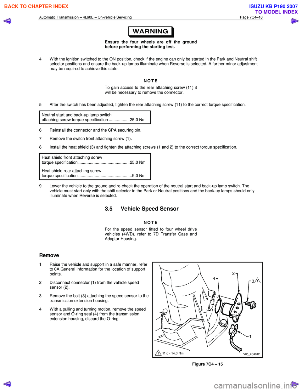
2 Disconnect connector (1) from the vehicle speed sensor (2).
3 Remove the bolt (3) attaching the speed sensor to the transmission extension housing.
4 With a pulling and turning motion, remove the speed sensor and O-ring seal (4) from the transmission
extension housing, discard the O-ring.
Figure 7C4 – 15
BACK TO CHAPTER INDEX
TO MODEL INDEX
ISUZU KB P190 2007
Page 3956 of 6020
Automatic Transmission – 4L60E – On-vehicle Servicing Page 7C4–43
If the verifier disc does not clip into place, the
quick-connect fitting is not engaged, rectify
as required.
10 As a security check, push and clip each verification disc into place over the quick-connect fittings. If difficulty is experienced, repeat the installation process until the verification disc can be clipped into place over the radiator
quick-connect fitting.
11 Snap the outlet cooler line (4) in the clip (5) of the radiator fan shroud.
12 Ensure the routeing of the cooler lines is correct and there is no fouling of the lines.
13 Tighten the screw attaching the cooler lines bracket to the correct torque specifications.
Transmission cooler lines bracket
attaching screw torque specification .................. 23.0 Nm
14 If required, top up the transmission fluid level (cold).
15 Start the engine and check for any fluid leak at the fittings. If a leak is found, stop the engine and rectify the leak.
16 Check and top up the transmission fluid to the correct level as required, refer to 2.1 Transmission Fluid.
3.18 Transmission Assembly
Remove
Disconnection of the battery affects certain
vehicle electronic systems. Refer to 6D1-3
Battery, before disconnecting the battery.
1 Disconnect the battery ground lead.
2 Raise the vehicle and support in a safe manner, refer to 0A General Information for the location of support points.
3 Remove the heat shield from the neutral start and back-up lamp switch, gently prise the selector cable from the transmission external manual shaft linkage and remove the selector cable from the bracket, refer to
3.3 Selector Cable Assembly.
4 Disconnect the harness connectors from the following:
a Vehicle speed sensor, refer to 3.5 Vehicle Speed Sensor.
b Neutral start and back-up switch, refer to 3.4 Neutral Start and Back-up Lamp Switch.
c For the following on four wheel drive vehicles (4W D), refer to 7D Transfer Case and Adaptor Housing:
• neutral switch,
• 2WD – 4WD shift actuator switch,
• speed sensor.
NOTE
If the battery is connected, avoid turning the
ignition switch to the ON position, as the transfer
case control module (TTCM) must first be
removed (memory to be cleared as Check 4W D
Indicator will light).
5 Remove the following components: a Front and centre exhaust assemblies, refer to 6F Exhaust System.
BACK TO CHAPTER INDEX
TO MODEL INDEX
ISUZU KB P190 2007
Page 3959 of 6020
Automatic Transmission – 4L60E – On-vehicle Servicing Page 7C4–46
Reinstall
1 If required on 4W D vehicle, reinstall the transfer case, refer to 7D Transfer Case and Adaptor Housing.
2 Ensure the transmission and the engine mating surfaces are clean and free of burrs.
3 Lubricate the torque converter spigot (7) with a small amount of high temperature wheel bearing grease, refer to Figure 7C4 – 62.
4 Install a new filler tube seal into the transmission case.
Support the transmission while installing the
attaching bolts to avoid damage to the torque
converter and flexplate. Do not have the
transmission hanging.
5 Bring the transmission up to the engine, inserting the filler tube and ensuring the locating dowels completely enter the torque converter housing.
6 Reconnect the breather hose to the top of the transmission case.
NOTE
The bolts attaching the torque converter housing
are facing forward except for the bolt in position ℑ
which is facing rearward.
7 With the transmission supported, install the bolt (1), nine places, attaching the torque converter housing to the engine and tighten to the correct torque specification following the sequence shown in
within Figure 7C4 – 62.
Torque converter housing attaching
bolt torque specification .......................... 52.0 – 66.0 Nm
8 Remove the access hole cover plate from the lower surface of the housing and push the torque converter forward to meet the flexplate, then hand start three new bolts (2) before tightening to the correct torque specification.
Reinstall the access hole cover plate.
Torque converter to flexplate attaching
bolt torque specification .......................... 60.0 – 70.0 Nm
9 Reinstall the bolt (3) and torque converter cover (4) on the transmission right-hand side and the bolt (5) and torque converter cover (6) on the transmission left-hand side, tighten the bolts to the correct torque specification.
Torque converter cover attaching
bolt torque specification .......................... 12.0 – 16.0 Nm
10 Reinstall the transmission fluid lines, refer to 3.17 Transmission Cooler Line/Hose Assemblies.
Prior to connecting the harness connector to
the transmission, check that all pins and
seals are in sound condition and the dust
boot is not torn or damaged.
11 Reconnect the transmission harness connector to the transmission as follows: a Push straight down on the connector body until a click is heard.
b Reinstall the dust boot ensuring it is correctly located.
12 Attach the harness clips to the right-hand and left-hand sides of the transmission case, refer to 12O Fuses, Relays and Wiring Harnesses.
13 On 4WD vehicle, connect the harness two clips from the upper side of the transfer case.
BACK TO CHAPTER INDEX
TO MODEL INDEX
ISUZU KB P190 2007