2007 ISUZU KB P190 wheel
[x] Cancel search: wheelPage 2533 of 6020
Engine Mechanical – V6 Page 6A1–54
3.1 Engine Oil
The procedure outlined below is typically the same for both rear wheel drive and all wheel drive vehicles.
Check
The following procedure is applicable to both rear wheel and all wheel drive vehicles
1 Run the engine to bring it to normal operating temperature.
2 Park the vehicle on a level surface. A vehicle that is not level will affect the accuracy of the level reading.
3 Stop the engine and wait 5 to 10 minutes to allow the oil to drain back into the oil pan.
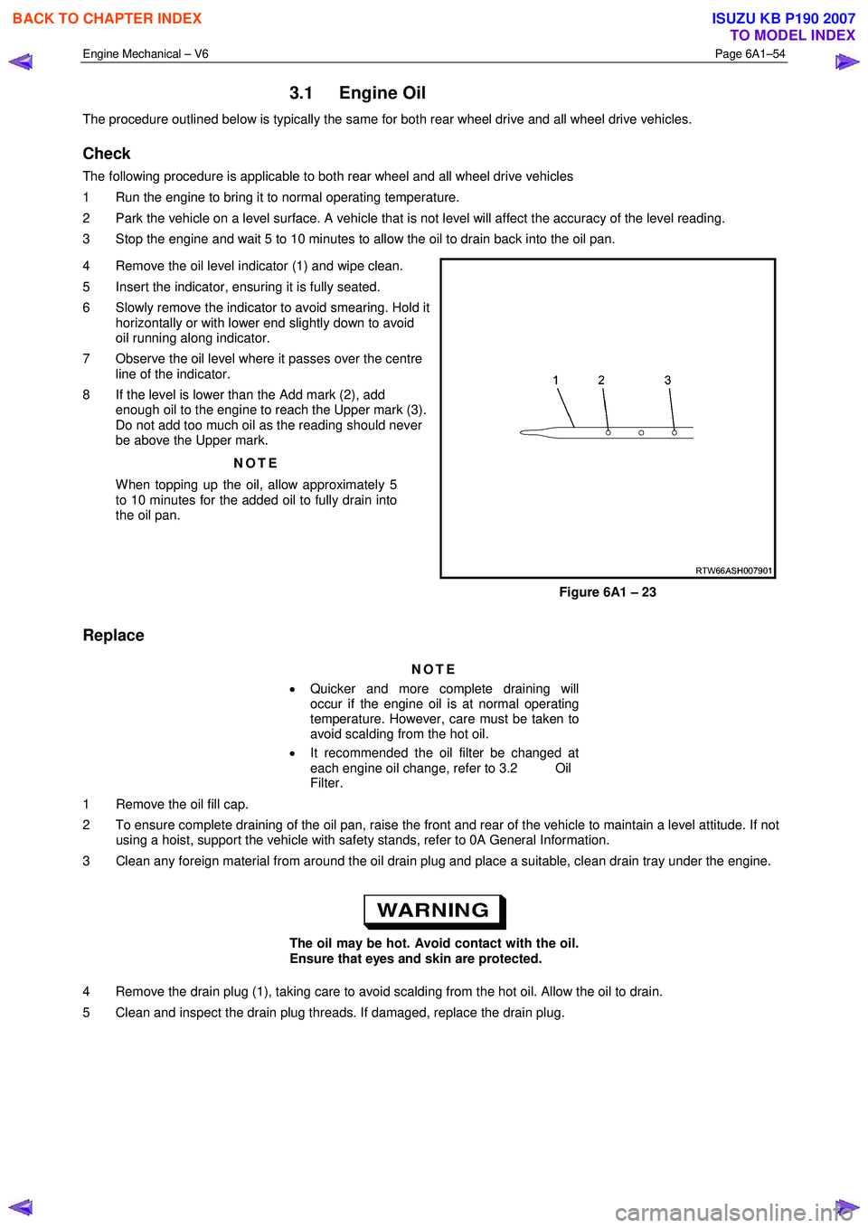
4 Remove the oil level indicator (1) and wipe clean.
5 Insert the indicator, ensuring it is fully seated.
6 Slowly remove the indicator to avoid smearing. Hold it horizontally or with lower end slightly down to avoid
oil running along indicator.
7 Observe the oil level where it passes over the centre line of the indicator.
8 If the level is lower than the Add mark (2), add enough oil to the engine to reach the Upper mark (3).
Do not add too much oil as the reading should never
be above the Upper mark.
NOTE
When topping up the oil, allow approximately 5
to 10 minutes for the added oil to fully drain into
the oil pan.
Figure 6A1 – 23
Replace
NOTE
• Quicker and more complete draining will
occur if the engine oil is at normal operating
temperature. However, care must be taken to
avoid scalding from the hot oil.
• It recommended the oil filter be changed at
each engine oil change, refer to 3.2 Oil
Filter.
1 Remove the oil fill cap.
2 To ensure complete draining of the oil pan, raise the front and rear of the vehicle to maintain a level attitude. If not using a hoist, support the vehicle with safety stands, refer to 0A General Information.
3 Clean any foreign material from around the oil drain plug and place a suitable, clean drain tray under the engine.
The oil may be hot. Avoid contact with the oil.
Ensure that eyes and skin are protected.
4 Remove the drain plug (1), taking care to avoid scalding from the hot oil. Allow the oil to drain.
5 Clean and inspect the drain plug threads. If damaged, replace the drain plug.
BACK TO CHAPTER INDEX
TO MODEL INDEX
ISUZU KB P190 2007
Page 2705 of 6020
Engine Mechanical – V6 Page 6A1–226
Crankshaft and Main Bearing Visual Inspection
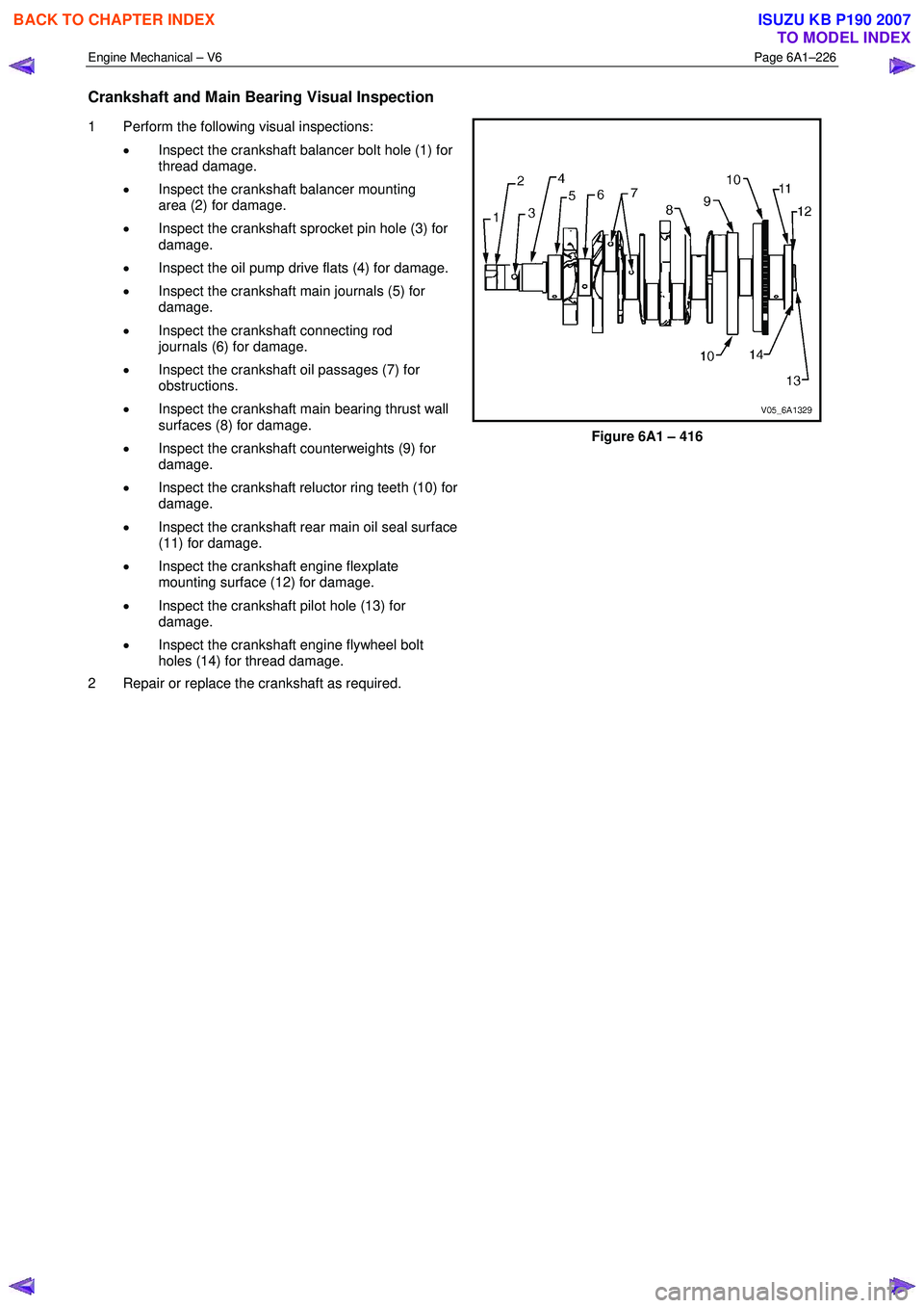
1 Perform the following visual inspections:
• Inspect the crankshaft balancer bolt hole (1) for
thread damage.
• Inspect the crankshaft balancer mounting
area (2) for damage.
• Inspect the crankshaft sprocket pin hole (3) for
damage.
• Inspect the oil pump drive flats (4) for damage.
• Inspect the crankshaft main journals (5) for
damage.
• Inspect the crankshaft connecting rod
journals (6) for damage.
• Inspect the crankshaft oil passages (7) for
obstructions.
• Inspect the crankshaft main bearing thrust wall
surfaces (8) for damage.
• Inspect the crankshaft counterweights (9) for
damage.
• Inspect the crankshaft reluctor ring teeth (10) for
damage.
• Inspect the crankshaft rear main oil seal surface
(11) for damage.
• Inspect the crankshaft engine flexplate
mounting surface (12) for damage.
• Inspect the crankshaft pilot hole (13) for
damage.
• Inspect the crankshaft engine flywheel bolt
holes (14) for thread damage.
2 Repair or replace the crankshaft as required.
Figure 6A1 – 416
BACK TO CHAPTER INDEX
TO MODEL INDEX
ISUZU KB P190 2007
Page 2785 of 6020
Engine Mechanical – V6 Page 6A1–8
Page 6A1–8
1 General Information
The HFV6 engine features a closed vee, deep skirt die cast aluminium cylinder block with cast iron cylinder liners,
internally balanced crankcase, full length wa ter jackets and six bolt main bearing caps.
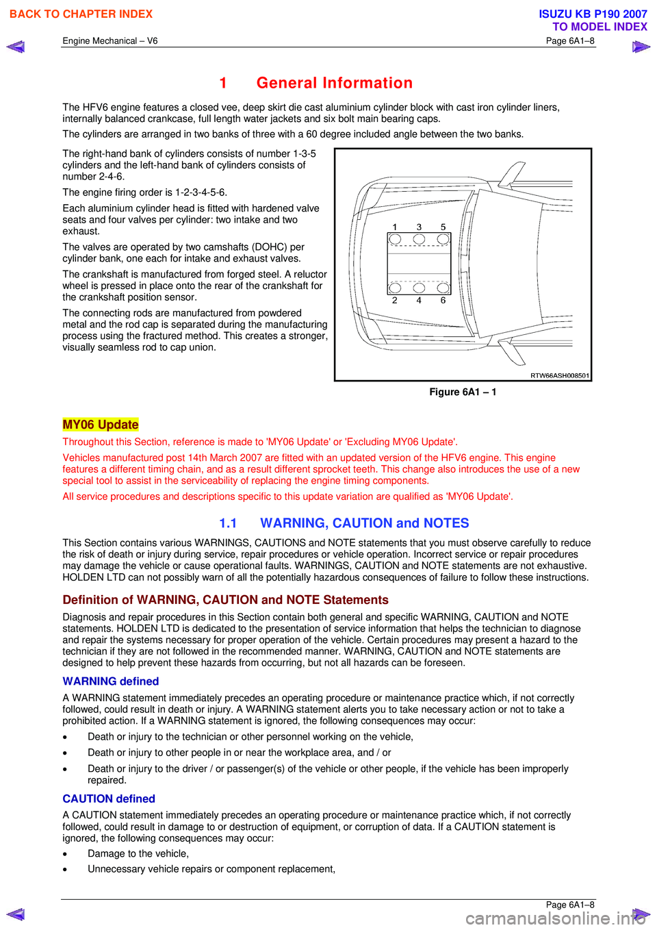
The cylinders are arranged in two banks of three with a 60 degree included angle between the two banks.
The right-hand bank of cylinders consists of number 1-3-5
cylinders and the left-hand bank of cylinders consists of
number 2-4-6.
The engine firing order is 1-2-3-4-5-6.
Each aluminium cylinder head is fitted with hardened valve
seats and four valves per cylinder: two intake and two
exhaust.
The valves are operated by two camshafts (DOHC) per
cylinder bank, one each for intake and exhaust valves.
The crankshaft is manufactured from forged steel. A reluctor
wheel is pressed in place onto the rear of the crankshaft for
the crankshaft position sensor.
The connecting rods are m anufactured from powdered
metal and the rod cap is separ ated during the manufacturing
process using the fractured me thod. This creates a stronger,
visually seamless rod to cap union.
Figure 6A1 – 1
MY06 Update
Throughout this Section, reference is made to 'MY06 Update' or 'Excluding MY06 Update'.
Vehicles manufactured post 14th Marc h 2007 are fitted with an updated version of the HFV6 engine. This engine
features a different timing chain, and as a result different sprocket teeth. This change also introduces the use of a new
special tool to assist in the serviceab ility of replacing the engine timing components.
All service procedures and descriptions specific to this update variation are qualified as 'MY06 Update'.
1.1 WARNING, CAUTION and NOTES
This Section contains various WARNING S, CAUTIONS and NOTE statements that y ou must observe carefully to reduce
the risk of death or injury during servic e, repair procedures or vehicle operation. Incorrect service or repair procedures
may damage the vehicle or cause operat ional faults. WARNINGS, CAUTION and NOTE statements are not exhaustive.
HOLDEN LTD can not possibly warn of a ll the potentially hazardous consequences of failure to follow these instructions.
Definition of WARNING, CAUTION and NOTE Statements
Diagnosis and repair procedures in this Section contain both general and specific WARNING, CAUTION and NOTE
statements. HOLDEN LTD is dedicated to the presentation of service information that helps the technician to diagnose
and repair the systems necessary for proper operation of the vehicle. Certain procedures may present a hazard to the
technician if they are not followed in the reco mmended manner. WARNING, CAUTION and NOTE statements are
designed to help prevent these hazards from o ccurring, but not all hazards can be foreseen.
WARNING defined
A WARNING statement immediately precedes an operating procedure or maint enance practice which, if not correctly
followed, could result in death or injury . A WARNING statement alerts you to ta ke necessary action or not to take a
prohibited action. If a WARNING statement is ignored, the following consequences may occur:
• Death or injury to the technician or other personnel working on the vehicle,
• Death or injury to other people in or near the workplace area, and / or
• Death or injury to the driver / or passenger(s) of the vehicle or other people, if the vehicle has been improperly
repaired.
CAUTION defined
A CAUTION statement immediately prec edes an operating procedure or maintenance practice which, if not correctly
followed, could result in damage to or destruction of equi pment, or corruption of data. If a CAUTION statement is
ignored, the following consequences may occur:
• Damage to the vehicle,
• Unnecessary vehicle repairs or component replacement,
BACK TO CHAPTER INDEX
TO MODEL INDEX
ISUZU KB P190 2007
Page 2787 of 6020
Engine Mechanical – V6 Page 6A1–10
Page 6A1–10
1.2 Engine Components
Major Component Assemblies
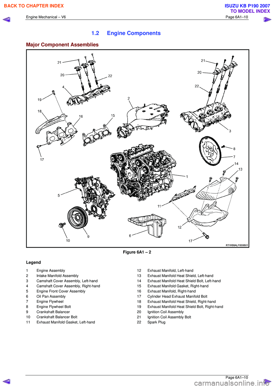
Figure 6A1 – 2
Legend
1 Engine Assembly
2 Intake Manifold Assembly
3 Camshaft Cover Assembly, Left-hand
4 Camshaft Cover Assembly, Right-hand
5 Engine Front Cover Assembly
6 Oil Pan Assembly
7 Engine Flywheel
8 Engine Flywheel Bolt
9 Crankshaft Balancer
10 Crankshaft Balancer Bolt
11 Exhaust Manifold Gasket, Left-hand 12 Exhaust Manifold, Left-hand
13 Exhaust Manifold Heat Shield, Left-hand
14 Exhaust Manifold Heat Shield Bolt, Left-hand
15 Exhaust Manifold Gasket, Right-hand
16 Exhaust Manifold, Right-hand
17 Cylinder Head Exhaust Manifold Bolt
18 Exhaust Manifold Heat Shield, Right-hand
19 Exhaust Manifold Heat Shield Bolt, Right-hand
20 Ignition Coil Assembly
21 Ignition Coil Assembly Bolt
22 Spark Plug
BACK TO CHAPTER INDEX
TO MODEL INDEX
ISUZU KB P190 2007
Page 2800 of 6020
Engine Mechanical – V6 Page 6A1–23
Page 6A1–23
Crankshaft
The crankshaft is a forged steel design with four main bearings. The number three main bearing controls crankshaft
thrust. A crankshaft position reluctor wheel is pressed onto the rear of the crankshaft, in front of the rear main journal.
The crankshaft is internally balanced with an integral oil pum p drive machined into the nose in front of the front main
journal.
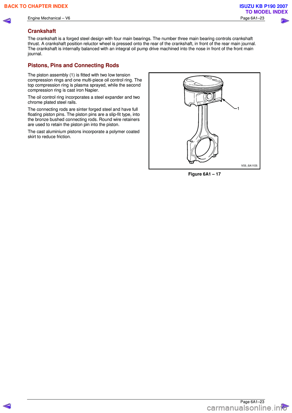
Pistons, Pins and Connecting Rods
The piston assembly (1) is fitted with two low tension
compression rings and one multi-piece oil control ring. The
top compression ring is plasma sprayed, while the second
compression ring is cast iron Napier.
The oil control ring incorpor ates a steel expander and two
chrome plated steel rails.
The connecting rods are sint er forged steel and have full
floating piston pins. The piston pi ns are a slip-fit type, into
the bronze bushed connecting rods. Round wire retainers
are used to retain the piston pin into the piston.
The cast aluminium pistons incorporate a polymer coated
skirt to reduce friction.
Figure 6A1 – 17
BACK TO CHAPTER INDEX
TO MODEL INDEX
ISUZU KB P190 2007
Page 2810 of 6020
Engine Mechanical – V6 Page 6A1–33
Page 6A1–33
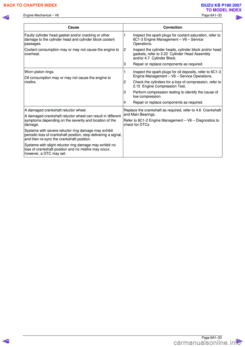
Cause Correction
Faulty cylinder head gasket and/or cracking or other
damage to the cylinder head and cylinder block coolant
passages.
Coolant consumption may or may not cause the engine to
overheat. 1 Inspect the spark plugs for
coolant saturation, refer to
6C1-3 Engine Management – V6 – Service
Operations.
2 Inspect the cylinder heads, cylinder block and/or head gaskets, refer to 3.22 Cylinder Head Assembly
and/or 4.7 Cylinder Block.
3 Repair or replace components as required.
Worn piston rings.
Oil consumption may or ma y not cause the engine to
misfire. 1 Inspect the spark plugs for oil deposits, refer to 6C1-3
Engine Management – V6 – Service Operations.
2 Check the cylinders for a loss of compression, refer to 2.15 Engine Compression Test.
3 Perform compression testing to identify the cause of
low compression.
4 Repair or replace components as required.
A damaged crankshaft reluctor wheel.
A damaged crankshaft reluctor wheel can result in different
symptoms depending on the severity and location of the
damage.
Systems with severe relu ctor ring damage may exhibit
periodic loss of crankshaft posit ion, stop delivering a signal,
and then re-sync the crankshaft position.
Systems with slight reluctor ring damage may exhibit no
loss of crankshaft position and no misfire may occur,
however, a DTC may set. Replace the crankshaft as required, refer to 4.6 Crankshaft
and Main Bearings.
Refer to 6C1-2 Engine Management – V6 – Diagnostics to
check for DTCs
BACK TO CHAPTER INDEX
TO MODEL INDEX
ISUZU KB P190 2007
Page 2818 of 6020
Engine Mechanical – V6 Page 6A1–41
Page 6A1–41
2.11 Engine Noise Under Load
NOTE
A cold piston knock which disappears in
approximately 1.5 minutes from start up, should
be considered acceptable. A cold engine knock
usually disappears when t he specific cylinder’s
secondary ignition circuit is grounded out during
diagnosis.
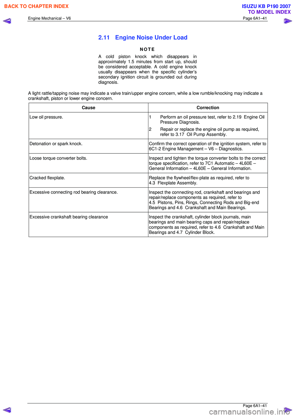
A light rattle/tapping noise may indicate a valve train/upper engine concern, while a low rumble/knocking may indicate a
crankshaft, piston or lower engine concern.
Cause Correction
Low oil pressure. 1 Perform an oil pressure test, refer to 2.19 Engine Oil
Pressure Diagnosis.
2 Repair or replace the engine oil pump as required, refer to 3.17 Oil Pump Assembly.
Detonation or spark knock. Confirm the correct operation of the ignition system, refer to
6C1-2 Engine Management – V6 – Diagnostics.
Loose torque converter bolts. Inspect and tighten the torque converter bolts to the correct
torque specification, refer to 7C1 Automatic – 4L60E –
General Information – 4L60E – General Information.
Cracked flexplate. Replace the flywheel/flex-plate as required, refer to
4.3 Flexplate Assembly.
Excessive connecting rod bearing clearance. Inspect the connecting rod, crankshaft and bearings and
repair/replace components as required, refer to
4.5 Pistons, Pins, Rings, Connecting Rods and Big-end
Bearings and 4.6 Crankshaft and Main Bearings.
Excessive crankshaft bearing clearance Inspect the crankshaft, cylinder block journals, main
bearings and main bearing caps and repair/replace
components as required, refer to 4.6 Crankshaft and Main
Bearings and 4.7 Cylinder Block.
BACK TO CHAPTER INDEX
TO MODEL INDEX
ISUZU KB P190 2007
Page 2819 of 6020
Engine Mechanical – V6 Page 6A1–42
Page 6A1–42
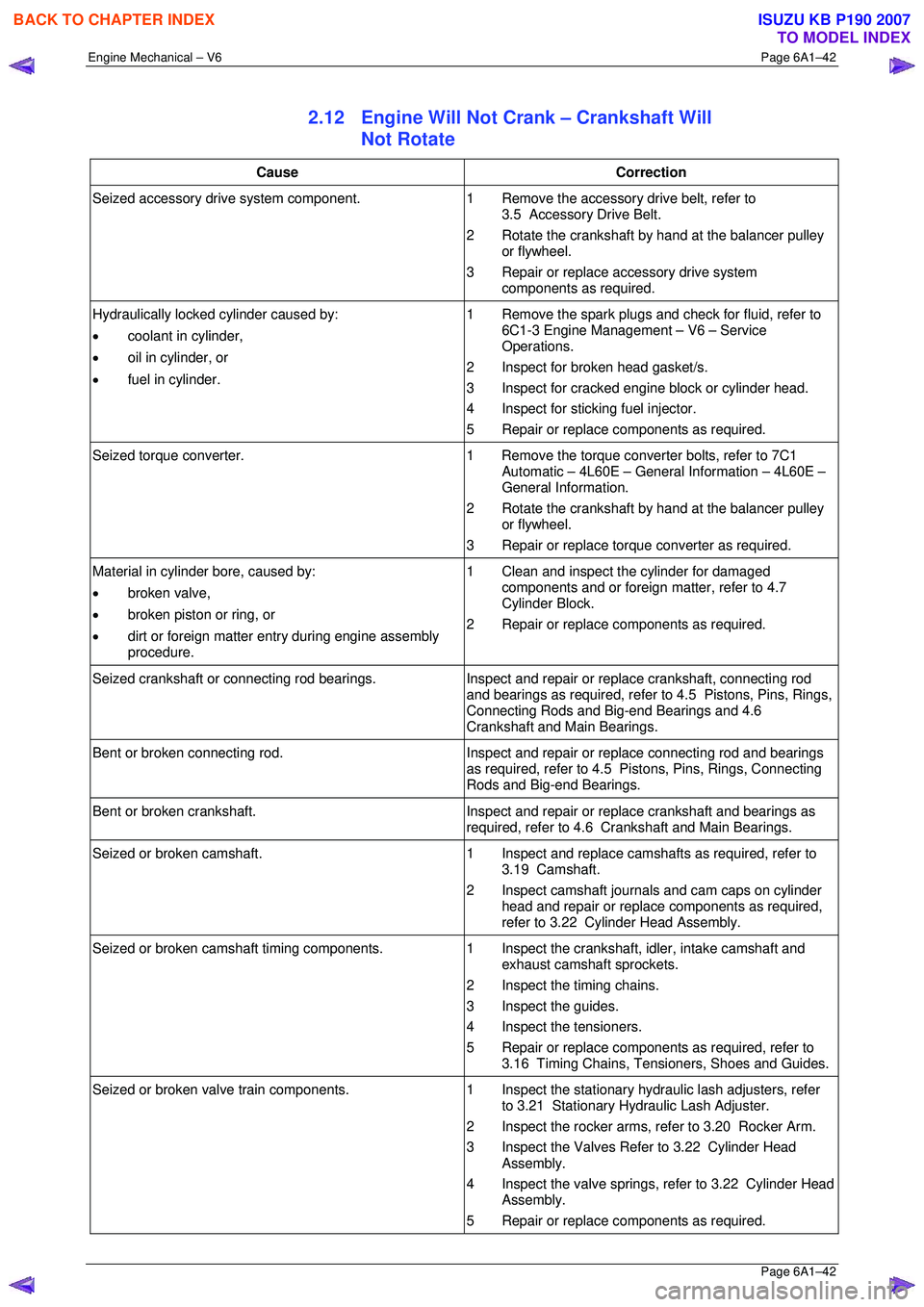
2.12 Engine Will Not Crank – Crankshaft Will
Not Rotate
Cause Correction
Seized accessory drive system component. 1 Remove the accessory drive belt, refer to
3.5 Accessory Drive Belt.
2 Rotate the crankshaft by hand at the balancer pulley or flywheel.
3 Repair or replace accessory drive system components as required.
Hydraulically locked cylinder caused by:
• coolant in cylinder,
• oil in cylinder, or
• fuel in cylinder. 1 Remove the spark plugs and check for fluid, refer to
6C1-3 Engine Management – V6 – Service
Operations.
2 Inspect for broken head gasket/s.
3 Inspect for cracked engine block or cylinder head.
4 Inspect for sticking fuel injector.
5 Repair or replace components as required.
Seized torque converter. 1 Remove the torque converter bolts, refer to 7C1
Automatic – 4L60E – General Information – 4L60E –
General Information.
2 Rotate the crankshaft by hand at the balancer pulley or flywheel.
3 Repair or replace torque converter as required.
Material in cylinder bore, caused by:
• broken valve,
• broken piston or ring, or
• dirt or foreign matter entry during engine assembly
procedure. 1 Clean and inspect the cylinder for damaged
components and or foreign matter, refer to 4.7
Cylinder Block.
2 Repair or replace components as required.
Seized crankshaft or connecting rod bearings. Inspect and repair or replace crankshaft, connecting rod
and bearings as required, refer to 4.5 Pistons, Pins, Rings,
Connecting Rods and Big-end Bearings and 4.6
Crankshaft and Main Bearings.
Bent or broken connecting rod. Inspect and repair or replace connecting rod and bearings
as required, refer to 4.5 Pistons, Pins, Rings, Connecting
Rods and Big-end Bearings.
Bent or broken crankshaft. Inspect and repair or replace crankshaft and bearings as
required, refer to 4.6 Crankshaft and Main Bearings.
Seized or broken camshaft. 1 Inspect and replace camshafts as required, refer to
3.19 Camshaft.
2 Inspect camshaft journals and cam caps on cylinder head and repair or replace components as required,
refer to 3.22 Cylinder Head Assembly.
Seized or broken camshaft timing components. 1 Inspect the crankshaft, idler, intake camshaft and
exhaust camshaft sprockets.
2 Inspect the timing chains.
3 Inspect the guides.
4 Inspect the tensioners.
5 Repair or replace components as required, refer to 3.16 Timing Chains, Tensioners, Shoes and Guides.
Seized or broken valve train components. 1 Inspect the stationary hydraulic lash adjusters, refer
to 3.21 Stationary Hydraulic Lash Adjuster.
2 Inspect the rocker arms, re fer to 3.20 Rocker Arm.
3 Inspect the Valves Refer to 3.22 Cylinder Head Assembly.
4 Inspect the valve springs, refer to 3.22 Cylinder Head Assembly.
5 Repair or replace components as required.
BACK TO CHAPTER INDEX
TO MODEL INDEX
ISUZU KB P190 2007