Page 1474 of 6020

6A-114 ENGINE MECHANICAL (4JK1/4JJ1)
015RY00010
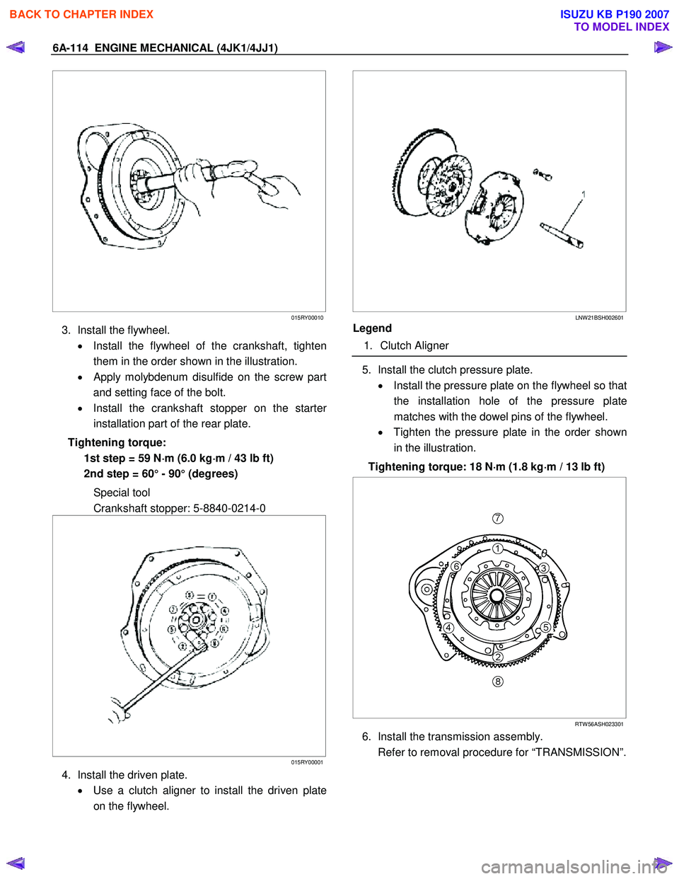
3. Install the flywheel.
• Install the flywheel of the crankshaft, tighten
them in the order shown in the illustration.
•
Apply molybdenum disulfide on the screw part
and setting face of the bolt.
• Install the crankshaft stopper on the starte
r
installation part of the rear plate.
Tightening torque: 1st step = 59 N ⋅
⋅⋅
⋅
m (6.0 kg ⋅
⋅⋅
⋅
m / 43 lb ft)
2nd step = 60° - 90° (degrees)
Special tool
Crankshaft stopper: 5-8840-0214-0
015RY00001
4. Install the driven plate.
• Use a clutch aligner to install the driven plate
on the flywheel.
LNW 21BSH002601
Legend
1. Clutch Aligner
5. Install the clutch pressure plate.
• Install the pressure plate on the flywheel so that
the installation hole of the pressure plate
matches with the dowel pins of the flywheel.
• Tighten the pressure plate in the order shown
in the illustration.
Tightening torque: 18 N ⋅
⋅⋅
⋅
m (1.8 kg ⋅
⋅⋅
⋅
m / 13 lb ft)
RTW 56ASH023301
6. Install the transmission assembly.
Refer to removal procedure for “TRANSMISSION”.
BACK TO CHAPTER INDEX
TO MODEL INDEX
ISUZU KB P190 2007
Page 1481 of 6020

ENGINE MECHANICAL (4JK1/4JJ1) 6A-121
3. Remove the crankshaft pulley.
Note:
Do not reuse the bolt and the washer.
LNW 61ASH005301
4. Remove the crankshaft front oil seal.
• Remove only the oil seal with a screwdriver o
r
the like, avoiding damage to the oil seal contact
surface on the front cover and the shaft.
Installation
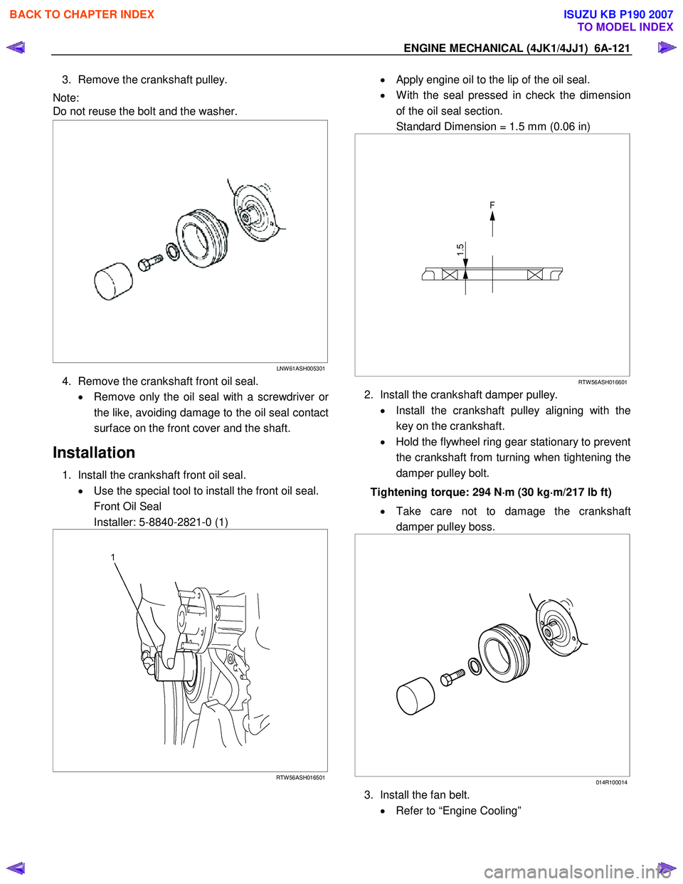
1. Install the crankshaft front oil seal. • Use the special tool to install the front oil seal.
Front Oil Seal
Installer: 5-8840-2821-0 (1)
RTW 56ASH016501
• Apply engine oil to the lip of the oil seal.
• W ith the seal pressed in check the dimension
of the oil seal section.
Standard Dimension = 1.5 mm (0.06 in)
RTW 56ASH016601
2. Install the crankshaft damper pulley.
• Install the crankshaft pulley aligning with the
key on the crankshaft.
• Hold the flywheel ring gear stationary to prevent
the crankshaft from turning when tightening the
damper pulley bolt.
Tightening torque: 294 N ⋅
⋅⋅
⋅
m (30 kg ⋅
⋅⋅
⋅
m/217 lb ft)
• Take care not to damage the crankshaft
damper pulley boss.
014R100014
3. Install the fan belt.
• Refer to “Engine Cooling”
BACK TO CHAPTER INDEX
TO MODEL INDEX
ISUZU KB P190 2007
Page 1483 of 6020
ENGINE MECHANICAL (4JK1/4JJ1) 6A-123
Crankshaft Rear Oil Seal
Components
RTW 56ALF002501
Legend 1. Crankshaft Rear Oil Seal
2. Flywheel
3. Driven Plate 4. Clutch Pressure Plate
5. Transmission Assembly
BACK TO CHAPTER INDEX
TO MODEL INDEX
ISUZU KB P190 2007
Page 1484 of 6020
6A-124 ENGINE MECHANICAL (4JK1/4JJ1)
Removal
1. Remove the flywheel.
Refer to "Flywheel". • W ith the oil seal pushed in deep, install the
special tool as shown in the illustration and
remove the oil seal.
Oil Seal Remover: 5-8840-2360-0
015LV002
Installation
1. Install the crankshaft rear oil seal.
• Use an oil seal install to install the crankshaft
rear oil seal.
Oil Seal Installer: 5-8840-2359-0
RTW 56ASH022901
2. Install the flywheel.
Refer to "Flywheel".
BACK TO CHAPTER INDEX
TO MODEL INDEX
ISUZU KB P190 2007
Page 1511 of 6020
ENGINE MECHANICAL (4JK1/4JJ1) 6A-151
Removal
1. Remove the engine assembly.
Refer to “Engine Assembly”.
2. Remove the oil level gage guide tube.
RTW 56ASH015601
3. Remove the oil pan.
RTW 56ASH015001
4. Disconnect the earth terminal (1) of crank case
side.
RTW 76ASH001801
5. Remove the flywheel.
Refer to “Flywheel”.
6. Remove the rear plate.
RTW 76ASH001901
Legend
1. Rear Plate
2. Bolt
BACK TO CHAPTER INDEX
TO MODEL INDEX
ISUZU KB P190 2007
Page 1514 of 6020
6A-154 ENGINE MECHANICAL (4JK1/4JJ1)
6. Install the rear plate.
• Tighten the bolts to the specified torque.
Tightening torque: 82 N ⋅
⋅⋅
⋅
m (8.4 kg ⋅
⋅⋅
⋅
m / 61 lb ft)
7. Install the flywheel.
Refer to “Flywheel”.
8. Connect the earth terminal of crank case side.
Note:
Do not allow the caulked portion of the terminal to
interfere with nearby parts.
9. Install the oil level gage guide tube. • Apply the engine oil to the O-ring.
• Tighten the bolts to the specified torque.
Tightening torque: 25 N ⋅
⋅⋅
⋅
m (2.5 kg ⋅
⋅⋅
⋅
m / 18 lb ft)
10. Install the engine assembly.
Refer to “Engine Assembly”.
BACK TO CHAPTER INDEX
TO MODEL INDEX
ISUZU KB P190 2007
Page 1582 of 6020

FUEL SYSTEM (4JK1/4JJ1) 6C-41
Removal
Note: W hen repairs to the fuel system have been
completed, start the engine and check the fuel system
for loose connections or leakage. For the fuel system
diagnosis, see Section "Drivability and Emission".
1. Disconnect the battery ground cable.
2. Slowly loosen the fuel filler cap.
Note: Be careful that fuel does not spout out because o
f
change of pressure in the fuel tank.
Note: Cover opening of the filler neck to prevent an
y
dust entering. 3. Jack up the vehicle.
4. Disconnect the quick connector (5) of the fuel tube at the fuel cooler way.
5. Remove fuel return hose (8) from the pipe.
6. Remove fixing bolt (7) of the bracket fuel coole
r
and remove bracket fuel cooler (6).
Note: Cover the opening of the pipe to prevent any dust
and fuel leakage.
Note: For remove fuel cooler, Remove bolts (10) of the
fuel cooler and remove fuel cooler.
7. Support underneath of the fuel tank with a lifter.
8. Remove the inner liner of the wheel house at rea
r
left side.
9. Remove fixing bolt of the filler neck from the body.
10. Disconnect the quick connector (5) of the fuel tube from the fuel pipe and the evapo tube from evapo
joint connector.
Note: Cover the quick connector to prevent any dust
entering and prevent fuel leakage.
Note: Refer to "Fuel Tube/Quick Connector Fittings" in
this section when performing any repairs.
11. Remove fixing bolt (1) of the tank band and remove the tank band (2).
12. Disconnect the pump and sender connector on the fuel pump and remove the harness from the weld
clip on the fuel tank.
13. Lower the fuel tank (3).
Note: W hen lowering the fuel tank from the vehicle, do
not scratch the hoses and tubes by contact with othe
r
parts.
Installation
1. Raise the fuel tank.
Note: W hen raising the fuel tank to the vehicle, do not
scratch the hoses and tubes by contact with other parts.
2. Connect the pump and sender connector to the fuel pump and install the harness to the weld clip
on the tank.
Note: The connector must be securely connected
against the stopper.
3. Install the tank band and fasten bolt.
Torque: 68 N ⋅
⋅⋅
⋅
m (6.9 kg ⋅
⋅⋅
⋅
m /50 lb ft)
Note: The anchor of the tank band must be securely
installed to the guide hole on the frame.
4. Connect the quick connector of the fuel tube to the fuel pipe and the evapo tube from evapo joint
connector.
Note: Pull off the left checker on the fuel pipe.
Note: Refer to "Fuel Tube/Quick Connector Fittings" in
this section when performing any repairs.
5. Install the filler neck to the body with bolt.
Note: For install the fuel cooler to the bracket with bolt.
Torque: 6.5 N ⋅
⋅⋅
⋅
m (0.7 kg ⋅
⋅⋅
⋅
m /61 lb in)
6. Install the bracket to Frame with bolt. Torque: 48 N ⋅
⋅⋅
⋅
m (4.9 kg ⋅
⋅⋅
⋅
m /35 lb ft)
7. Install the fuel return hose at the fuel cooler way.
8. Install the quick connector at the fuel cooler way.
9. Install the inner liner of the wheel house at rear left side.
10. Remove lifter from the fuel tank.
11. Lower the vehicle.
12. Tighten the filler cap until at least three clicks.
13. Connect the battery ground cable.
BACK TO CHAPTER INDEX
TO MODEL INDEX
ISUZU KB P190 2007
Page 1954 of 6020

ENGINE CONTROL SYSTEM (4JK1/4JJ1) 6E-337
Fuel System ChecksInspect the fuel system for the following conditions. Refer to Fuel System Check chart
and appropriate procedure in the Fuel System section.
• Air in the fuel system.
• Water contamination in the fuel.
• Fuel waxing or icing.
• Fuel filter indicator lamp is continuously or frequently turned ON with engine run.
• External fuel leaks or high engine oil level.
• In-tank fuel pump operation. Refer to In-tank Fuel Pump System Check in this section.
• Fuel leak off from the fuel pressure limiter valve and fuel injectors.
• Fuel lines between the fuel tank and fuel supply pump for being crushed, kinked, tightness, cracks and plugged.
• A plugged fuel tank vent valve and hose.
• Inside the fuel tank for any foreign material that may be getting drawn into the fuel line pickup causing a blocked condition.
• Fuel supply pump operation.
Notice: The fuel supply pump must be timed to the engine and adjustment value must
be learned to the ECM.
• Perform the Cylinder Balance Test with a scan tool.
• Perform the Injector Force Drive with a scan tool.
• Observe the Fuel Compensation for each cylinder at idle on the scan tool.
Air Intake System Checks Inspect the air intake system for the following conditions.
• Air cleaner, air intake ducts and charge air cooler for a restriction, holes, or leaks.
• A restriction in the turbocharger inlet duct.
• Intake throttle valve for a stuck condition.
• A restriction or leak in the intake manifold.
• A restriction or damaged at MAF sensor.
• Perform the Swirl Control Solenoid Test with a scan tool. Inspect the diaphragm valve operation when it commanded ON/ OFF.
• A worn or damaged turbocharger turbine wheel, shaft or compressor wheel. Refer to turbocharger inspection in the Engine Mechanical section.
• Turbocharger wastegate valve operation. Refer to wastegate valve inspection in the Engine Mechanical section. (Standard output)
• Turbocharger nozzle control actuator operation. Refer to Turbocharger Control System Check in this section. (High output)
Exhaust System Checks Inspect the exhaust system for a possible restriction. Refer to the Exhaust System
section.
Engine Mechanical Checks Inspect the engine mechanical for the following conditions. Refer to the Engine
Mechanical section.
• Poor cylinder compression.
• Improper valve gap.
• Broken or weak valve springs.
• Worn camshaft lobes.
Additional Checks • Inspect the EGR system operating correctly. Refer to EGR Control System Check in
this section.
• Observe the Park/ Neutral Switch parameter with a scan tool.
• Inspect for an engine overheat condition. Refer to Engine Cooling section.
• Inspect the A/C operation.
• Inspect the torque converter clutch (TCC) operation. (A/T only).
Checks
Action
BACK TO CHAPTER INDEX
TO MODEL INDEX
ISUZU KB P190 2007