2007 ISUZU KB P190 wheel
[x] Cancel search: wheelPage 1362 of 6020
6A-2 ENGINE MECHANICAL (4JK1/4JJ1)
Special Tools ...................................................6A-110
Flywheel .............................................................6A-111 Components ....................................................6A-111
Removal ..........................................................6A-111
Inspection ........................................................6A-113
Installation .......................................................6A-113
Torque Specifications......................................6A-115
Special Tools ...................................................6A-115
Gear Case Assembly .........................................6A-116 Components ....................................................6A-116
Removal ..........................................................6A-117
Installation .......................................................6A-118
Torque Specifications......................................6A-119
Crankshaft Front Oil Seal ...................................6A-120 Components ....................................................6A-120
Removal ..........................................................6A-120
Installation .......................................................6A-121
Torque Specifications......................................6A-122
Special Tools ...................................................6A-122
Crankshaft Rear Oil Seal ...................................6A-123 Components ....................................................6A-123
Removal ..........................................................6A-124
Installation .......................................................6A-124
Special Tools ...................................................6A-125
Crankshaft ..........................................................6A-126 Components ....................................................6A-126
Removal ..........................................................6A-127
Disassembly ....................................................6A-127
Reassembly.....................................................6A-128
Inspection ........................................................6A-128
Installation .......................................................6A-132
Torque Specifications......................................6A-135
Cylinder Block ....................................................6A-136 Components ....................................................6A-136
Removal ..........................................................6A-136
Inspection ........................................................6A-137
Installation .......................................................6A-139
Lubrication System .............................................6A-140 Service Precautions ........................................6A-140
Functional Check ............................................6A-141
Oil Filter Cartridge ..............................................6A-143 Components ....................................................6A-143
Removal ..........................................................6A-143
Installation .......................................................6A-143
Special Tools ...................................................6A-144
Oil Filter Assembly and Oil Cooler .....................6A-145 Components ....................................................6A-145
Removal ..........................................................6A-145
Disassembly ....................................................6A-146
Reassembly.....................................................6A-147 Installation ....................................................... 6A-147
Crank Case and Oil Pan .................................... 6A-150 Components .................................................... 6A-150
Removal .......................................................... 6A-151
Disassembly .................................................... 6A-152
Reassembly .................................................... 6A-152
Installation ....................................................... 6A-153
Torque Specifications...................................... 6A-155
Oil Pump ............................................................ 6A-156 Components .................................................... 6A-156
Removal .......................................................... 6A-156
Disassembly .................................................... 6A-157
Reassembly .................................................... 6A-158
Inspection ........................................................ 6A-158
Installation ....................................................... 6A-159
Oil Pressure SW ................................................ 6A-161 Components .................................................... 6A-161
Removal .......................................................... 6A-162
Inspection ........................................................ 6A-162
Installation ....................................................... 6A-162
Circuit check.................................................... 6A-162
Air Cleaner Element ........................................... 6A-163 Removal .......................................................... 6A-163
Cleaning .......................................................... 6A-163
Installation ....................................................... 6A-163
BACK TO CHAPTER INDEX
TO MODEL INDEX
ISUZU KB P190 2007
Page 1363 of 6020
ENGINE MECHANICAL (4JK1/4JJ1) 6A-3
ISUZU DIESEL ENGINE (4JK1/4JJ1)
Service Precautions
Matters that require attention in terms of
maintenance
To prevent damage to the engine and ensure reliabilit
y
of its performance, pay attention to the following in
maintaining the engine:
• W hen lifting up or supporting the engine, do not
apply a jack on the oil pan.
W hen taking down the engine on the ground, do not make the bearing surface of the oil pan touch
the ground directly. Use a wooden frame, fo
r
example, to support the engine with the engine
foot and the flywheel housing.
Because there is only a small clearance between the oil pan and the oil pump strainer, it can
damage the oil pan and the oil strainer.
• W hen the air duct or air cleaner is removed, cove
r
the air intake opening to prevent foreign matter
from getting into the cylinder. If it gets
contaminated, it can considerably damage the
cylinder and others while the engine is operating.
• W hen maintaining the engine, never fail to remove
the battery earth cable. If not, it may damage the
wire harness or electrical parts. If you need
electricity on for the purpose of inspection, fo
r
instance, watch out for short circuits and others.
•
Apply engine oil to the sliding contact surfaces of
the engine before reassembling it. This ensures
adequate lubrication when the engine is first
started.
• W hen valve train parts, pistons, piston rings,
connecting rods, connecting rod bearings o
r
crankshaft journal bearings are removed, put them
in order and keep them.
• W hen installing them, put them back in the same
location they were removed from.
• Gaskets, oil seals, O-rings, etc. must be replaced
with new ones when the engine is reassembled.
•
As for parts where a liquid gasket is used, remove
an old liquid gasket completely and clean it up
thoroughly so that no oil, water or dust is clinging
to them. Then, apply the designated liquid gasket
to each place anew before assembly.
• Surfaces covered with liquid gasket must be
assembled within 5 minutes of gasket application.
If more than 5 minutes has elapsed, remove the
existing liquid gasket and apply a new liquid
gasket.
• W hen assembling or installing parts, fasten them
with the prescribed tightening torque so that the
y
are installed properly.
Matters that require attention in specifically dealing
with this engine.
Holes or clearances in the fuel system, which serve as
a passage of fuel, including the inside of the injector,
are made with extreme precision. For this reason, the
y
are highly sensitive to foreign matter and, if it gets in, it
can lead to an accident on the road, for instance; thus,
make sure that foreign matter is prevented from getting
in.
W hen servicing the fuel system, every precaution must
be taken to prevent the entry of foreign material into the
system.
• Before beginning the service procedure, wash the
fuel line and the surrounding area.
• Perform the service procedures with clean hands.
Do not wear work gloves.
• Immediately after removing the fuel hose and/o
r
fuel pipe, carefully tape vinyl bags over the
exposed ends of the hose or pipe.
• If parts are to be replaced (fuel hose, fuel pipe,
etc.) do not open the new part packaging until
installation.
Work procedure
• The fuel opening must be quickly sealed when
removing the fuel pipe, injection pipe, fuel injector,
fuel supply pump, and fuel rail.
• The eyebolts and gasket must be stored in a clean
parts box with a lid to prevent adhesion of foreign
matter.
• Fuel leakage could cause fires. Therefore, afte
r
finishing the work, wipe off the fuel that has leaked
out and make sure there is no fuel leakage afte
r
starting the engine.
BACK TO CHAPTER INDEX
TO MODEL INDEX
ISUZU KB P190 2007
Page 1368 of 6020
6A-8 ENGINE MECHANICAL (4JK1/4JJ1)
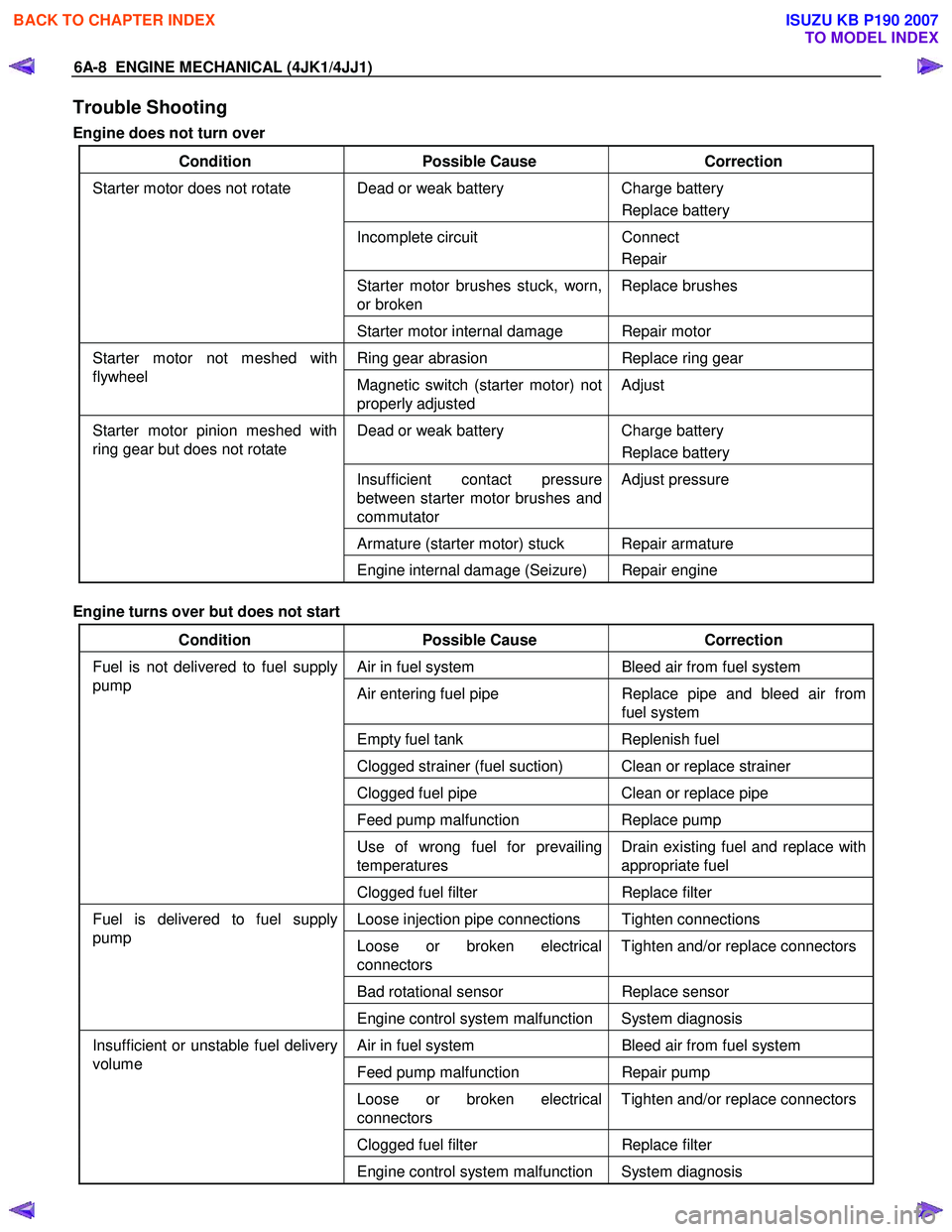
Trouble Shooting
Engine does not turn over
Condition Possible Cause Correction
Dead or weak battery Charge battery
Replace battery
Incomplete circuit Connect
Repair
Starter motor brushes stuck, worn,
or broken Replace brushes
Starter motor does not rotate
Starter motor internal damage Repair motor
Ring gear abrasion Replace ring gear Starter motor not meshed with
flywheel Magnetic switch (starter motor) not
properly adjusted Adjust
Dead or weak battery
Charge battery
Replace battery
Insufficient contact pressure
between starter motor brushes and
commutator Adjust pressure
Armature (starter motor) stuck Repair armature
Starter motor pinion meshed with
ring gear but does not rotate
Engine internal damage (Seizure) Repair engine
Engine turns over but does not start
Condition Possible Cause Correction
Air in fuel system Bleed air from fuel system
Air entering fuel pipe Replace pipe and bleed air from
fuel system
Empty fuel tank Replenish fuel
Clogged strainer (fuel suction) Clean or replace strainer
Clogged fuel pipe Clean or replace pipe
Feed pump malfunction Replace pump
Use of wrong fuel for prevailing
temperatures Drain existing fuel and replace with
appropriate fuel
Fuel is not delivered to fuel supply
pump
Clogged fuel filter Replace filter
Loose injection pipe connections Tighten connections
Loose or broken electrical
connectors Tighten and/or replace connectors
Bad rotational sensor
Replace sensor
Fuel is delivered to fuel supply
pump
Engine control system malfunction System diagnosis
Air in fuel system Bleed air from fuel system
Feed pump malfunction Repair pump
Loose or broken electrical
connectors Tighten and/or replace connectors
Clogged fuel filter
Replace filter
Insufficient or unstable fuel delivery
volume
Engine control system malfunction System diagnosis
BACK TO CHAPTER INDEX
TO MODEL INDEX
ISUZU KB P190 2007
Page 1396 of 6020
6A-36 ENGINE MECHANICAL (4JK1/4JJ1)
Inspection
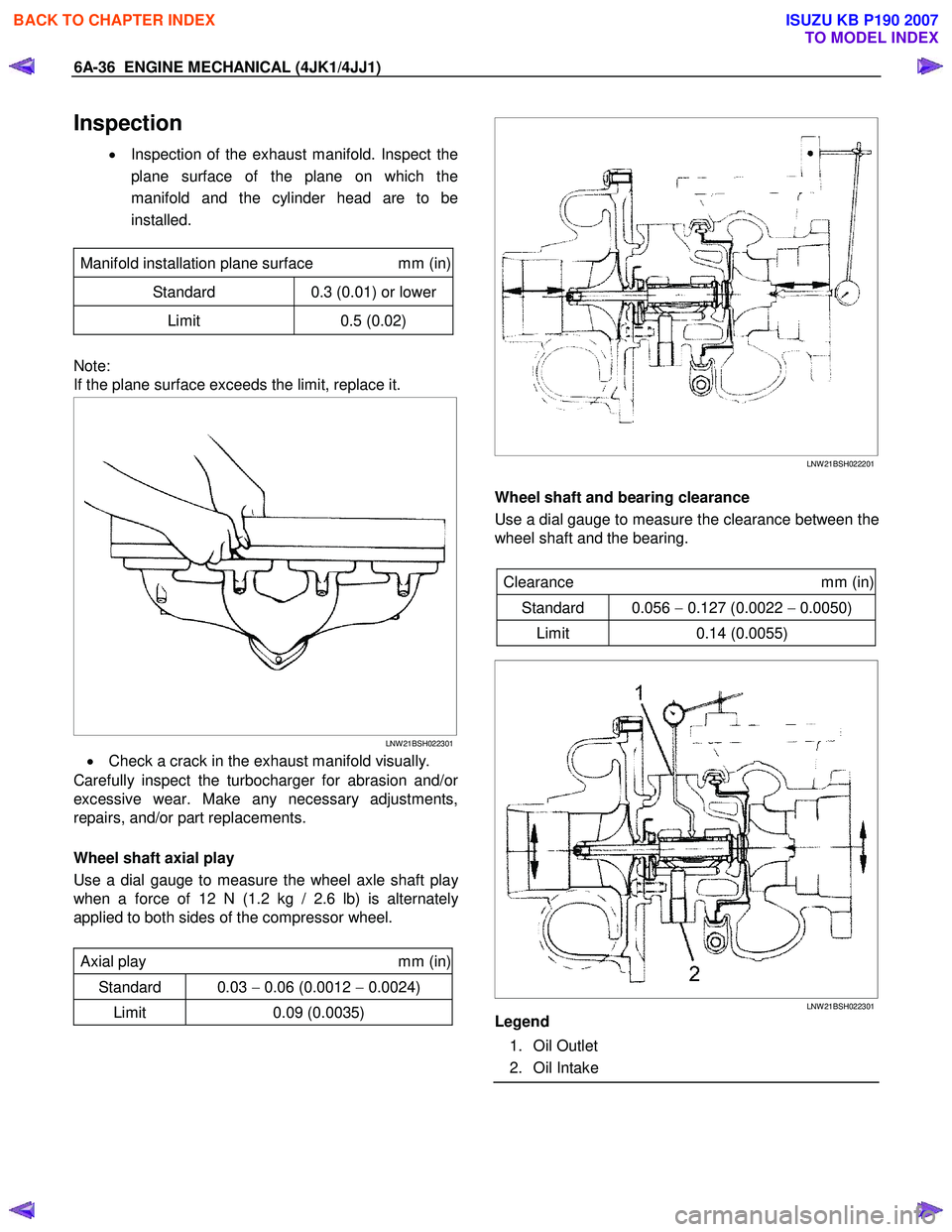
• Inspection of the exhaust manifold. Inspect the
plane surface of the plane on which the
manifold and the cylinder head are to be
installed.
Manifold installation plane surface mm (in)
Standard 0.3 (0.01) or lower
Limit 0.5 (0.02)
Note:
If the plane surface exceeds the limit, replace it.
LNW 21BSH022301
• Check a crack in the exhaust manifold visually.
Carefully inspect the turbocharger for abrasion and/o
r
excessive wear. Make any necessary adjustments,
repairs, and/or part replacements.
Wheel shaft axial play
Use a dial gauge to measure the wheel axle shaft pla
y
when a force of 12 N (1.2 kg / 2.6 lb) is alternately
applied to both sides of the compressor wheel.
Axial play mm (in)
Standard 0.03 − 0.06 (0.0012 − 0.0024)
Limit 0.09 (0.0035)
LNW 21BSH022201
Wheel shaft and bearing clearance
Use a dial gauge to measure the clearance between the
wheel shaft and the bearing.
Clearance mm (in)
Standard 0.056 − 0.127 (0.0022 − 0.0050)
Limit 0.14 (0.0055)
LNW 21BSH022301
Legend
1. Oil Outlet
2. Oil Intake
BACK TO CHAPTER INDEX
TO MODEL INDEX
ISUZU KB P190 2007
Page 1403 of 6020
ENGINE MECHANICAL (4JK1/4JJ1) 6A-43
Inspection
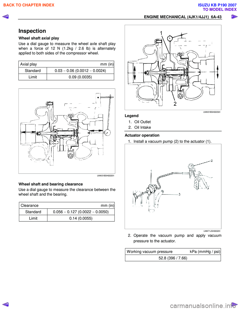
Wheel shaft axial play
Use a dial gauge to measure the wheel axle shaft pla
y
when a force of 12 N (1.2kg / 2.6 lb) is alternately
applied to both sides of the compressor wheel.
Axial play mm (in)
Standard 0.03 − 0.06 (0.0012 − 0.0024)
Limit 0.09 (0.0035)
LNW 21BSH022201
Wheel shaft and bearing clearance
Use a dial gauge to measure the clearance between the
wheel shaft and the bearing.
Clearance mm (in)
Standard 0.056 − 0.127 (0.0022 − 0.0050)
Limit 0.14 (0.0055)
LNW 21BSH022301
Legend
1. Oil Outlet
2. Oil Intake
Actuator operation
1. Install a vacuum pump (2) to the actuator (1).
LNW 71JSH000201
2. Operate the vacuum pump and apply vacuum
pressure to the actuator.
W orking vacuum pressure kPa (mmHg / psi)
52.8 (396 / 7.66)
BACK TO CHAPTER INDEX
TO MODEL INDEX
ISUZU KB P190 2007
Page 1471 of 6020
ENGINE MECHANICAL (4JK1/4JJ1) 6A-111
Flywheel
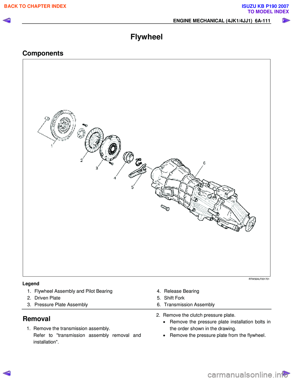
Components
RTW 56ALF001701
Legend 1. Flywheel Assembly and Pilot Bearing
2. Driven Plate
3. Pressure Plate Assembly 4. Release Bearing
5. Shift Fork
6. Transmission Assembly
Removal
1. Remove the transmission assembly.
Refer to "transmission assembly removal and installation".
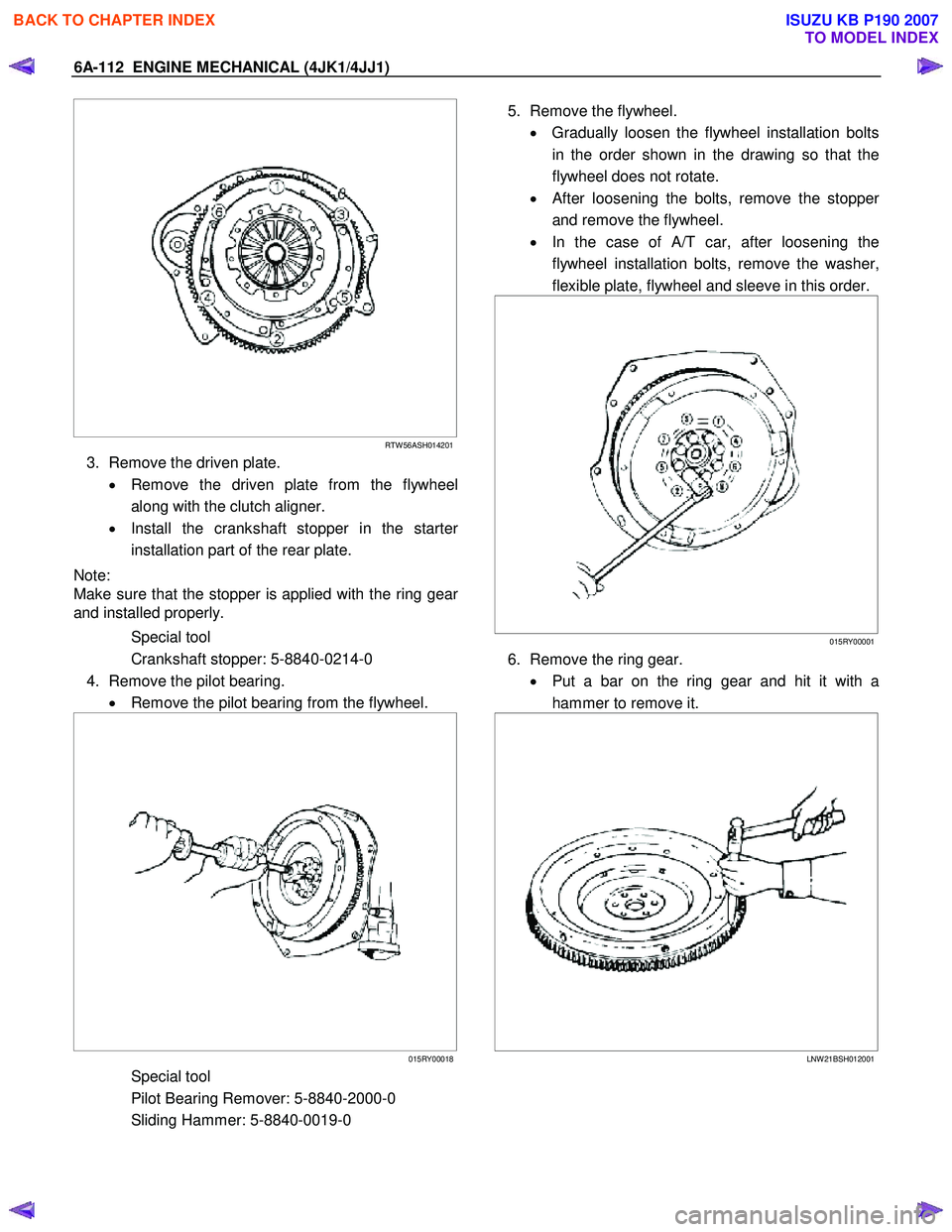
2. Remove the clutch pressure plate.
• Remove the pressure plate installation bolts in
the order shown in the drawing.
• Remove the pressure plate from the flywheel.
BACK TO CHAPTER INDEX
TO MODEL INDEX
ISUZU KB P190 2007
Page 1472 of 6020
6A-112 ENGINE MECHANICAL (4JK1/4JJ1)
RTW 56ASH014201
3. Remove the driven plate.
• Remove the driven plate from the flywheel
along with the clutch aligner.
• Install the crankshaft stopper in the starte
r
installation part of the rear plate.
Note:
Make sure that the stopper is applied with the ring gea
r
and installed properly.
Special tool
Crankshaft stopper: 5-8840-0214-0
4. Remove the pilot bearing. • Remove the pilot bearing from the flywheel.
015RY00018
Special tool
Pilot Bearing Remover: 5-8840-2000-0
Sliding Hammer: 5-8840-0019-0
5. Remove the flywheel.
• Gradually loosen the flywheel installation bolts
in the order shown in the drawing so that the
flywheel does not rotate.
•
After loosening the bolts, remove the stopper
and remove the flywheel.
• In the case of A/T car, after loosening the
flywheel installation bolts, remove the washer,
flexible plate, flywheel and sleeve in this order.
015RY00001
6. Remove the ring gear.
• Put a bar on the ring gear and hit it with a
hammer to remove it.
LNW 21BSH012001
BACK TO CHAPTER INDEX
TO MODEL INDEX
ISUZU KB P190 2007
Page 1473 of 6020
ENGINE MECHANICAL (4JK1/4JJ1) 6A-113
Inspection
1. Visual inspection
• Inspect the flywheel friction surface for cracks
and damages, and replace it if it has
abnormality.
• Inspect the tooth part of the ring gear, replace
the ring gear if it has damage or serious wear.
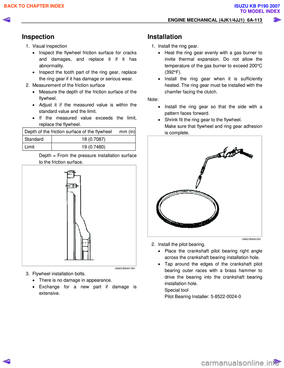
2. Measurement of the friction surface • Measure the depth of the friction surface of the
flywheel.
•
Adjust it if the measured value is within the
standard value and the limit.
• If the measured value exceeds the limit,
replace the flywheel.
Depth of the friction surface of the flywheel mm (in)
Standard 18 (0.7087)
Limit 19 (0.7480)
Depth = From the pressure installation surface
to the friction surface.
LNW 21BSH011901
3. Flywheel installation bolts.
• There is no damage in appearance.
• Exchange for a new part if damage is
extensive.
Installation
1. Install the ring gear.
• Heat the ring gear evenly with a gas burner to
invite thermal expansion. Do not allow the
temperature of the gas burner to exceed 200°C
(392°F).
• Install the ring gear when it is sufficientl
y
heated. The ring gear must be installed with the
chamfer facing the clutch.
Note: • Install the ring gear so that the side with a
pattern faces forward.
• Shrink fit the ring gear to the flywheel.
Make sure that flywheel and ring gear adhesion is complete.
LNW 21BSH01201
2. Install the pilot bearing.
• Place the crankshaft pilot bearing right angle
across the crankshaft bearing installation hole.
• Tap around the edges of the crankshaft pilot
bearing outer races with a brass hammer to
drive the bearing into the crankshaft bearing
installation hole.
Special tool
Pilot Bearing Installer: 5-8522-0024-0
BACK TO CHAPTER INDEX
TO MODEL INDEX
ISUZU KB P190 2007