2007 ISUZU KB P190 wheel
[x] Cancel search: wheelPage 1307 of 6020
Engine Control System (4JH1) 6E-273
Checks Action
Air Intake System Checks Inspect the air intake system for the following conditions.
• Inspect the air cleaner and air intake ducts for a restriction, holes, or leaks.
• Inspect for a restriction or leak in the intercooler.
• Inspect for a restriction in the turbocharger inlet duct.
• Inspect for a restriction or deposit in the intake throttle bore.
• Inspect for a restriction or leak in the intake manifold.
• Inspect for a restriction or damage at MAF sensor.
• Inspect for a worn or damaged turbocharger turbine wheel, shaft or compressor
wheel. Refer to turbocharger inspection in the Engine Mechanical section.
Exhaust System Checks Inspect the exhaust system for a possible restriction. Refer to the Exhaust System
section.
• Inspect for a restriction in the catalytic converter or exhaust pipes.
Engine Mechanical Check Inspect the engine mechanical for the following conditions. Refer to the Engine
Mechanical section.
• Inspect for poor cylinder compression. Proper compression is more than 2100 kPa
(309 psi).
• Inspect for incorrect basic engine parts such as camshaft, cylinder head, pistons,
etc.
• Inspect for any excessive oil entering combustion chamber.
• Improper mechanical timing
• Improper valve gap
• Broken or weak valve springs
• W orn camshaft lobes
Additional Checks •
Inspect the EGR system operating correctly.
• Inspect the excessive blow-by gasses.
• Inspect the scan tool Data List in this section.
Excessive Smoke (White Smoke)
Checks Action
DIFINITION:W hite smoke under load, idle or start up hot or cold.
Preliminary Check •
Ensure the vehicle has an actual problem.
• Inspect the engine control module (ECM) and fuel injection pump control unit (PCU)
grounds for being clean, tight, and in their proper locations.
• Inspect the fuel quality (cetane index).
• Inspect the Service Bulletins for ECM software updates.
Sensor Check Inspect the engine control sensors for the following conditions. Refer to the scan tool
Data List in this section.
• Use the scan tool to compare the Engine Coolant Temperature (ECT) with the Intake
Air Temperature (IAT) and Fuel Temperature (FT) on a cold engine condition. If the
difference among temperature reading is more than 5°C (9°F) on a cold engine,
check for high resistance on the low reference circuit and signal circuit or for a
skewed sensor.
Notice: The mass air flow (MAF) sensor is heated and as a result the IAT sensor may
indicate a higher than normal intake air temperature if the ignition switch is being ON.
FT sensor is internal to the PCU and it is part of the fuel injection pump assembly.
• Inspect the crankshaft position (CKP) sensor is tight and the flywheel circumference
is not damaged.
Fuel System Checks Inspect the fuel system for the following conditions. Refer to the Fuel System section.
• Inspect the fuel injection nozzle(s) for proper splay condition or operating pressure.
Notice: Only first stage of operating pressure can be checked.
• Inspect the timing device operating correctly. Observe the Actual Injection Timing
parameter with the scan tool while running the engine. The Actual Injection Timing
parameter must follow the Desired Injection Timing within 2°CA on each engine
speed. Engine idle > around 2000 RPM> around 3000 RPM. If not, inspect the fuel
system restriction, air in the fuel or fuel injection pump operation.
BACK TO CHAPTER INDEX
TO MODEL INDEX
ISUZU KB P190 2007
Page 1308 of 6020
6E-274 Engine Control System (4JH1)
Checks Action
Air Intake System Checks Inspect the air intake system for the following conditions.
• Inspect the air cleaner and air intake ducts for a restriction, holes, or leaks.
• Inspect for a restriction or leak in the intercooler.
• Inspect for a restriction in the turbocharger inlet duct.
• Inspect for a restriction or leak in the intake manifold.
• Inspect for a restriction or damage at MAF sensor.
• Inspect for a worn or damaged turbocharger turbine wheel, shaft or compressor
wheel. Refer to turbocharger inspection in the Engine Mechanical section.
Engine Mechanical Checks Inspect the engine mechanical for the following conditions. Refer to the Engine
Mechanical section.
• Inspect for poor cylinder compression. Proper compression is more than 2100 kPa
(309 psi).
• Inspect for incorrect basic engine parts such as camshaft, cylinder head, pistons,
etc.
• Improper mechanical timing
• Improper valve gap
• Broken or weak valve springs
• W orn camshaft lobes
• Inspect for any excessive fuel entering combustion chamber.
• Inspect for coolant entering the combustion chamber.
Electrical System Checks Inspect the engine electrical for the following conditions. Refer to the Engine Electrical
section.
• Inspect the glow plug control (preheating) system operation.
BACK TO CHAPTER INDEX
TO MODEL INDEX
ISUZU KB P190 2007
Page 1319 of 6020
Engine Control System (4JH1) 6E-285
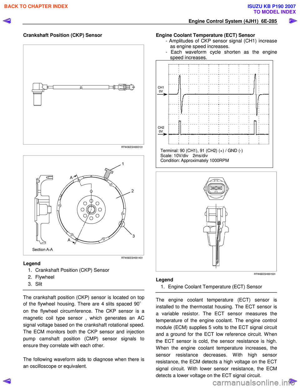
Crankshaft Position (CKP) Sensor
RTW 06ESH000101
RTW 66ESH001401
Legend
1. Crankshaft Position (CKP) Sensor
2. Flywheel
3. Slit
The crankshaft position (CKP) sensor is located on top
of the flywheel housing. There are 4 slits spaced 90 °
on the flywheel circumference. The CKP sensor is a
magnetic coil type sensor , which generates an AC
signal voltage based on the crankshaft rotational speed.
The ECM monitors both the CKP sensor and injection
pump camshaft position (CMP) sensor signals to
ensure they correlate with each other.
The following waveform aids to diagnose when there is
an oscilloscope or equivalent.
Engine Coolant Temperature (ECT) Sensor
- Amplitudes of CKP sensor signal (CH1) increase as engine speed increases.
- Each waveform cycle shorten as the engine speed increases.
Terminal: 90 (CH1), 91 (CH2) (+) / GND (-)
Scale: 10V/div 2ms/div
Condition: Approximately 1000RPM
CH1
0V
CH2 0V
RTW 66ESH001501
Legend
1. Engine Coolant Temperature (ECT) Sensor
The engine coolant temperature (ECT) sensor is
installed to the thermostat housing. The ECT sensor is
a variable resistor. The ECT sensor measures the
temperature of the engine coolant. The engine control
module (ECM) supplies 5 volts to the ECT signal circuit
and a ground for the ECT low reference circuit. W hen
the ECT sensor is cold, the sensor resistance is high.
W hen the engine coolant temperature increases, the
sensor resistance decreases. W ith high senso
r
resistance, the ECM detects a high voltage on the ECT
signal circuit. W ith lower sensor resistance, the ECM
detects a lower voltage on the ECT signal circuit.
BACK TO CHAPTER INDEX
TO MODEL INDEX
ISUZU KB P190 2007
Page 1329 of 6020
Engine Control System (4JH1) 6E-295
The timing control valve (TCV) acts as a variable
throttle, using the rapid opening and closing (cycling)
of the valve needle in the TCV.
At normal operation,
the TCV controls the pressure acting on the annula
r
chamber so that the hydraulic stopper cam move to
any position, from the retard position to the advance
position. At this time, the duty ratio is set by the fuel
injection pump control unit (PCU).
When control current flows to the TCV coil, the valve
needle opens and the fuel annular chamber flows
through the orifice to the feed pump inlet.
Consequently, the pressure of the annular chambe
r
decreases and the hydraulic stopper is moved to the
retard side.
When control current to the TCV coil is cut, the valve
needle closes and the return passage is closed.
Consequently, the pressure of the annular chambe
r
increases and the hydraulic stopper is moved to the
advance side.
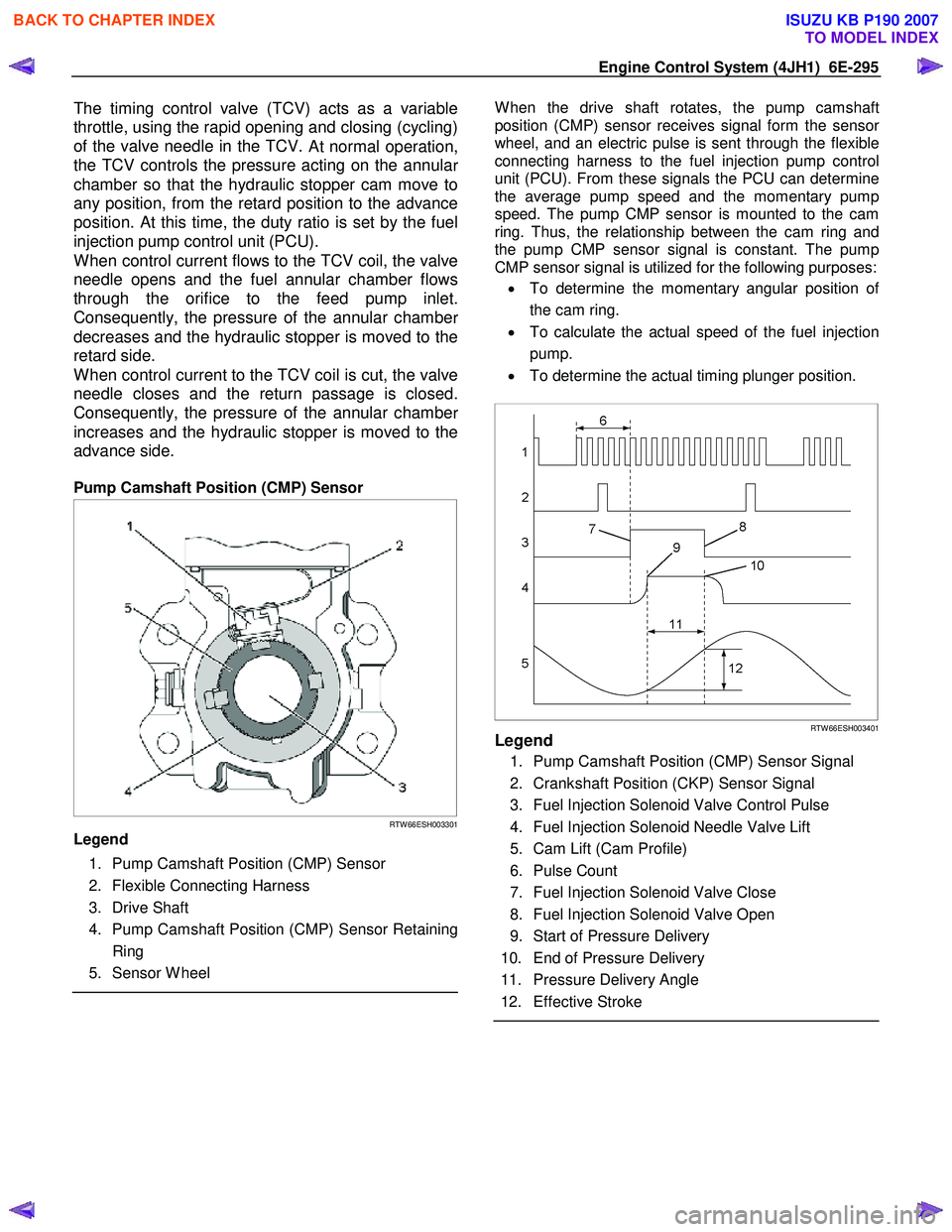
Pump Camshaft Position (CMP) Sensor
RTW 66ESH003301
Legend
1. Pump Camshaft Position (CMP) Sensor
2. Flexible Connecting Harness
3. Drive Shaft
4. Pump Camshaft Position (CMP) Sensor Retaining Ring
5. Sensor W heel
W hen the drive shaft rotates, the pump camshaft
position (CMP) sensor receives signal form the senso
r
wheel, and an electric pulse is sent through the flexible
connecting harness to the fuel injection pump control
unit (PCU). From these signals the PCU can determine
the average pump speed and the momentary pump
speed. The pump CMP sensor is mounted to the cam
ring. Thus, the relationship between the cam ring and
the pump CMP sensor signal is constant. The pump
CMP sensor signal is utilized for the following purposes:
• To determine the momentary angular position o
f
the cam ring.
• To calculate the actual speed of the fuel injection
pump.
• To determine the actual timing plunger position.
RTW 66ESH003401Legend
1. Pump Camshaft Position (CMP) Sensor Signal
2. Crankshaft Position (CKP) Sensor Signal
3. Fuel Injection Solenoid Valve Control Pulse
4. Fuel Injection Solenoid Needle Valve Lift
5. Cam Lift (Cam Profile)
6. Pulse Count
7. Fuel Injection Solenoid Valve Close
8. Fuel Injection Solenoid Valve Open
9. Start of Pressure Delivery
10. End of Pressure Delivery
11. Pressure Delivery Angle
12. Effective Stroke
BACK TO CHAPTER INDEX
TO MODEL INDEX
ISUZU KB P190 2007
Page 1332 of 6020
6E-298 Engine Control System (4JH1)
Turbocharger Description
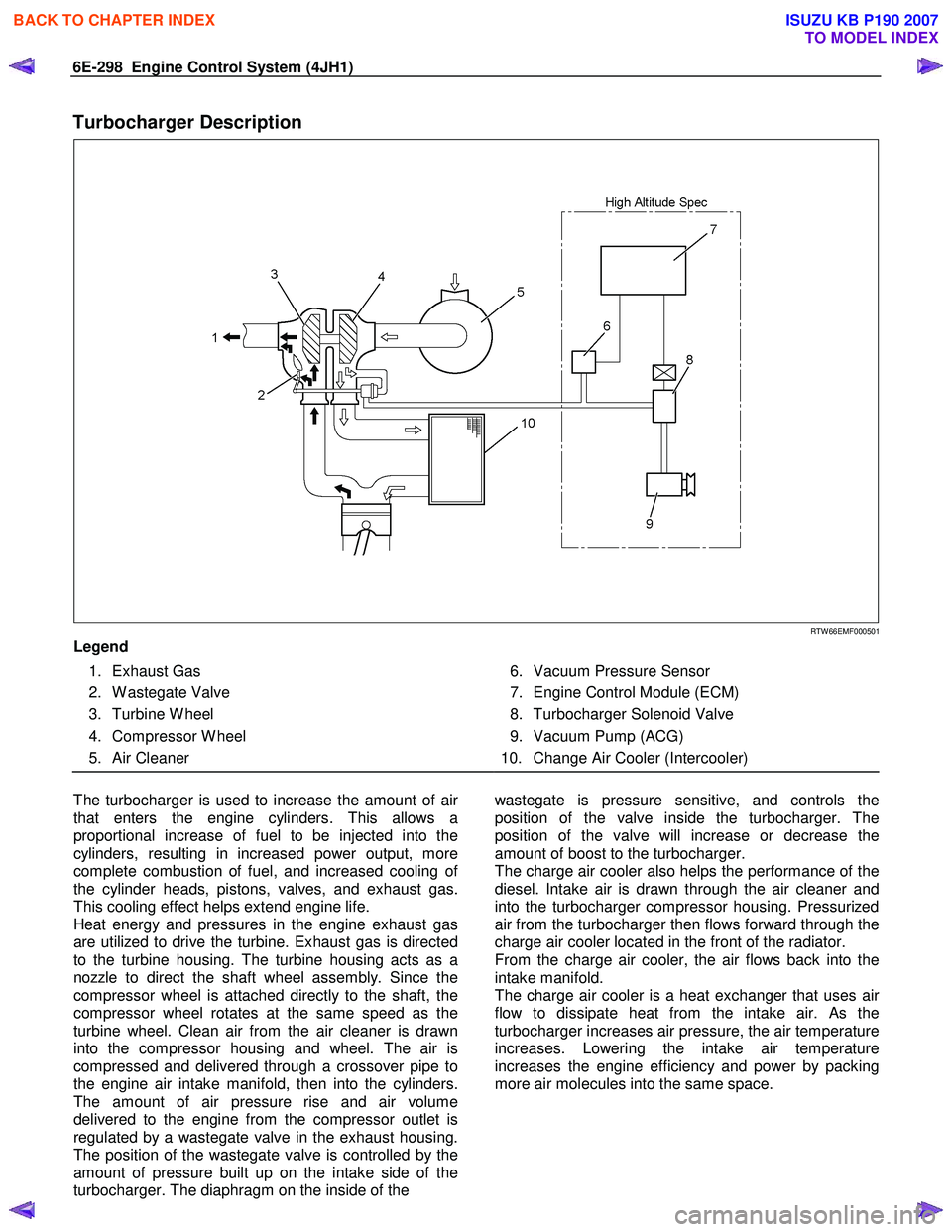
RTW 66EMF000501
Legend
1. Exhaust Gas
2. W astegate Valve
3. Turbine W heel
4. Compressor W heel
5. Air Cleaner
6. Vacuum Pressure Sensor
7. Engine Control Module (ECM)
8. Turbocharger Solenoid Valve
9. Vacuum Pump (ACG)
10. Change Air Cooler (Intercooler)
The turbocharger is used to increase the amount of ai
r
that enters the engine cylinders. This allows a
proportional increase of fuel to be injected into the
cylinders, resulting in increased power output, more
complete combustion of fuel, and increased cooling o
f
the cylinder heads, pistons, valves, and exhaust gas.
This cooling effect helps extend engine life.
Heat energy and pressures in the engine exhaust gas
are utilized to drive the turbine. Exhaust gas is directed
to the turbine housing. The turbine housing acts as a
nozzle to direct the shaft wheel assembly. Since the
compressor wheel is attached directly to the shaft, the
compressor wheel rotates at the same speed as the
turbine wheel. Clean air from the air cleaner is drawn
into the compressor housing and wheel. The air is
compressed and delivered through a crossover pipe to
the engine air intake manifold, then into the cylinders.
The amount of air pressure rise and air volume
delivered to the engine from the compressor outlet is
regulated by a wastegate valve in the exhaust housing.
The position of the wastegate valve is controlled by the
amount of pressure built up on the intake side of the
turbocharger. The diaphragm on the inside of the
wastegate is pressure sensitive, and controls the
position of the valve inside the turbocharger. The
position of the valve will increase or decrease the
amount of boost to the turbocharger.
The charge air cooler also helps the performance of the
diesel. Intake air is drawn through the air cleaner and
into the turbocharger compressor housing. Pressurized
air from the turbocharger then flows forward through the
charge air cooler located in the front of the radiator.
From the charge air cooler, the air flows back into the
intake manifold.
The charge air cooler is a heat exchanger that uses ai
r
flow to dissipate heat from the intake air. As the
turbocharger increases air pressure, the air temperature
increases. Lowering the intake air temperature
increases the engine efficiency and power by packing
more air molecules into the same space.
BACK TO CHAPTER INDEX
TO MODEL INDEX
ISUZU KB P190 2007
Page 1349 of 6020
6F – 16 EXHAUST SYSTEM
GENERAL DESCRIPTION
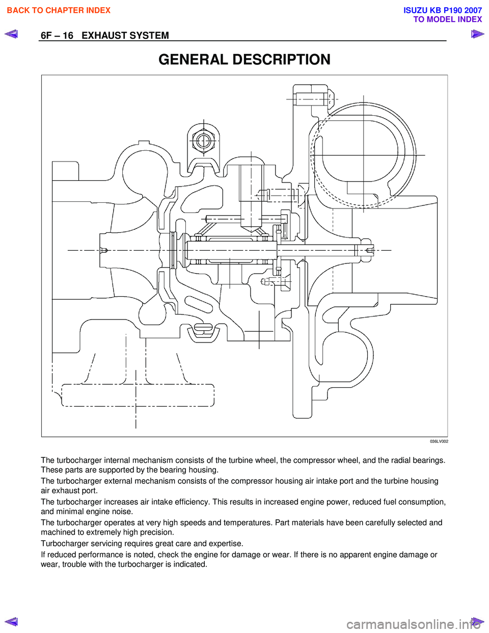
036LV002
The turbocharger internal mechanism consists of the turbine wheel, the compressor wheel, and the radial bearings.
These parts are supported by the bearing housing.
The turbocharger external mechanism consists of the compressor housing air intake port and the turbine housing
air exhaust port.
The turbocharger increases air intake efficiency. This results in increased engine power, reduced fuel consumption,
and minimal engine noise.
The turbocharger operates at very high speeds and temperatures. Part materials have been carefully selected and
machined to extremely high precision.
Turbocharger servicing requires great care and expertise.
If reduced performance is noted, check the engine for damage or wear. If there is no apparent engine damage or
wear, trouble with the turbocharger is indicated.
BACK TO CHAPTER INDEX
TO MODEL INDEX
ISUZU KB P190 2007
Page 1350 of 6020
EXHAUST SYSTEM 6F – 17
INSPECTION AND REPAIR
Make the necessary adjustments, repairs, and part replacements if excessive wear or damage is discovered during
inspection.
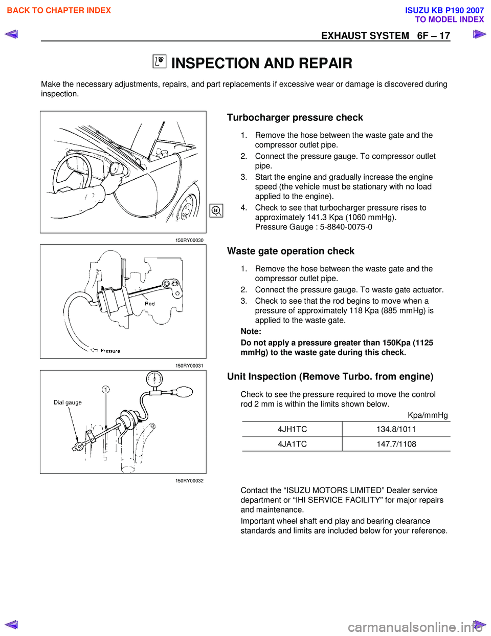
Turbocharger pressure check
1. Remove the hose between the waste gate and the
compressor outlet pipe.
2. Connect the pressure gauge. To compressor outlet pipe.
3. Start the engine and gradually increase the engine speed (the vehicle must be stationary with no load
applied to the engine).
4. Check to see that turbocharger pressure rises to approximately 141.3 Kpa (1060 mmHg).
Pressure Gauge : 5-8840-0075-0
150RY00030
Waste gate operation check
1. Remove the hose between the waste gate and the compressor outlet pipe.
2. Connect the pressure gauge. To waste gate actuator.
3. Check to see that the rod begins to move when a pressure of approximately 118 Kpa (885 mmHg) is
applied to the waste gate.
Note:
Do not apply a pressure greater than 150Kpa (1125
mmHg) to the waste gate during this check.
150RY00031
Unit Inspection (Remove Turbo. from engine)
Check to see the pressure required to move the control
rod 2 mm is within the limits shown below.
Kpa/mmHg
4JH1TC 134.8/1011
4JA1TC 147.7/1108
150RY00032
Contact the “ISUZU MOTORS LIMITED” Dealer service
department or “IHI SERVICE FACILITY” for major repairs
and maintenance.
Important wheel shaft end play and bearing clearance
standards and limits are included below for your reference.
BACK TO CHAPTER INDEX
TO MODEL INDEX
ISUZU KB P190 2007
Page 1351 of 6020
6F – 18 EXHAUST SYSTEM
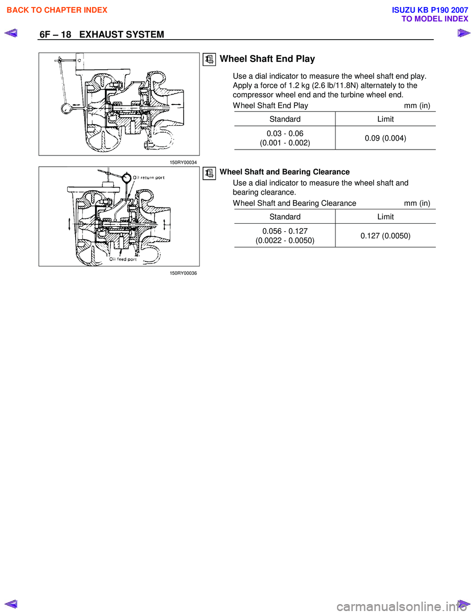
Wheel Shaft End Play
Use a dial indicator to measure the wheel shaft end play.
Apply a force of 1.2 kg (2.6 lb/11.8N) alternately to the
compressor wheel end and the turbine wheel end.
W heel Shaft End Play mm (in)
Standard Limit
0.03 - 0.06
(0.001 - 0.002) 0.09 (0.004)
150RY00034
Wheel Shaft and Bearing Clearance
Use a dial indicator to measure the wheel shaft and
bearing clearance.
W heel Shaft and Bearing Clearance mm (in)
Standard Limit
0.056 - 0.127
(0.0022 - 0.0050) 0.127 (0.0050)
150RY00036
BACK TO CHAPTER INDEX
TO MODEL INDEX
ISUZU KB P190 2007