2007 ISUZU KB P190 wheel
[x] Cancel search: wheelPage 2843 of 6020
Engine Mechanical – V6 Page 6A1–66
Page 6A1–66
3 Minor Service Operations
ATTENTION
The V6 engine is a combination of numerous components, containing machined, honed, polished and lapped
surfaces manufactured on the latest, high technology production equipment. Many of the components
contain tolerances measured in thousa ndths of a millimetre. Consequently, when any e ngine component is to
be serviced, care and cleanliness are extremely important.
Prior to re-assembly of the engine, all components mu st be cleaned and inspected in accordance with the
relevant clean and inspect procedur es throughout this Section, and repl aced or repaired where required.
In addition to cleaning and inspecting components, a liberal coating of engine oil should be applied to friction
surfaces during assembly to protect and lubr icate the surfaces on initial operation.
When performing any service operation, it should be understood that correct cleaning and protection of
machined surfaces and friction areas is part of the repair procedure. This is considered standard workshop
practice, even if not specifically stated. Torque va lues must be used as specified during reassembly to
ensure correct retention of all components.
Through out this section, fastener torque wrench sp ecifications may be accompanied with the following
identification marks:
■ Fasteners must be replaced after loosening.
Fasteners either have micro encapsulated sealant a pplied or incorporate a mechanical thread lock and
should only be re-used once. If in doubt, replacement is recommended.
If one of these identification marks is present alongs ide a fastener torque wrench specification, the
recommendation regarding that fastener must be adhered to.
3.1 Engine Oil
The procedure outlined below is typically the same for both rear wheel drive and all wheel drive vehicles.
Check
The following procedure is applicable to both rear wheel and all wheel drive vehicles
1 Run the engine to bring it to normal operating temperature.
2 Park the vehicle on a level surface. A vehicle that is not level will affect the accuracy of the level reading.
3 Stop the engine and wait 5 to 10 minutes to a llow the oil to drain back into the oil pan.
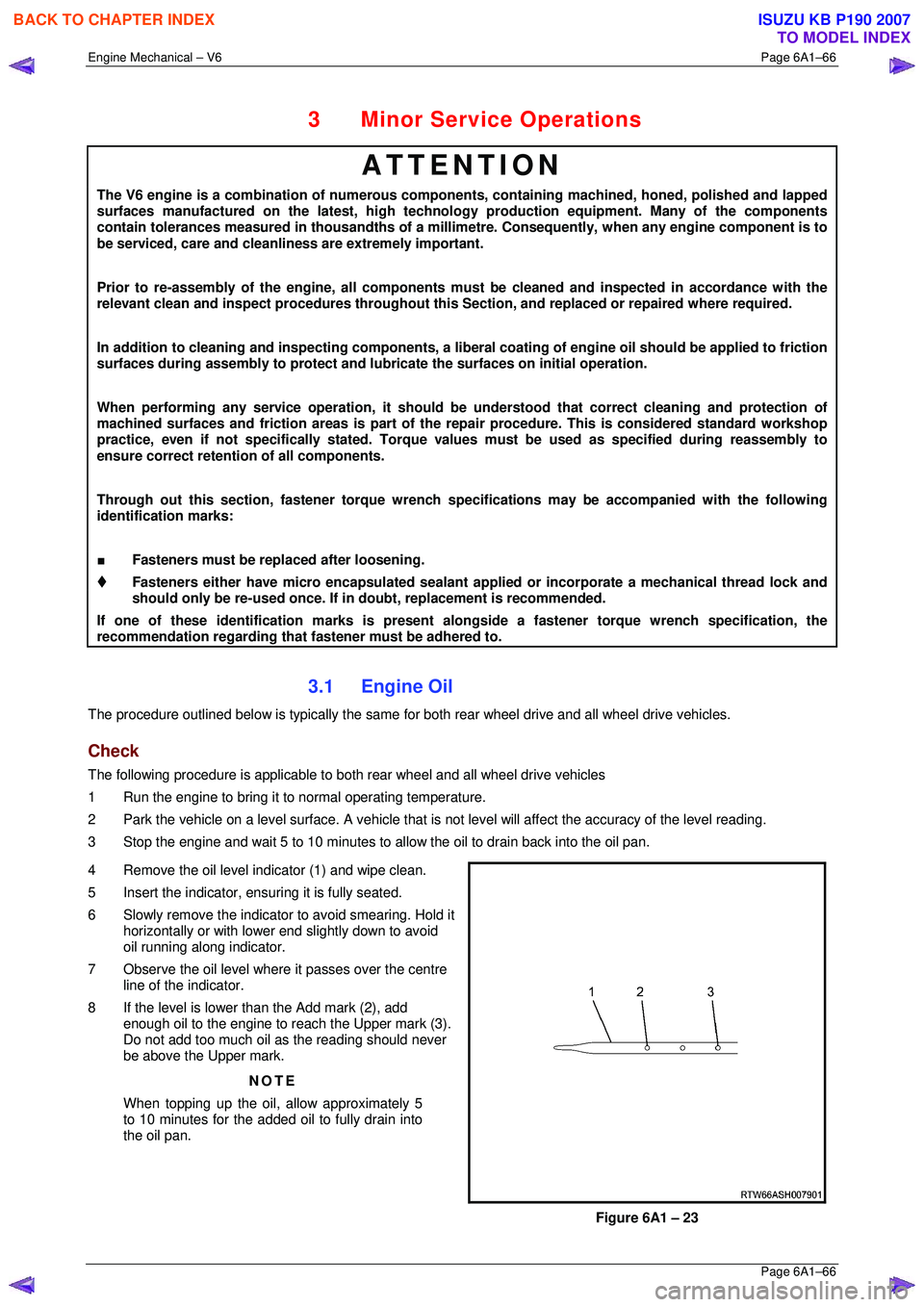
4 Remove the oil level indicator (1) and wipe clean.
5 Insert the indicator, ens uring it is fully seated.
6 Slowly remove the indicator to avoid smearing. Hold it horizontally or with lower end slightly down to avoid
oil running along indicator.
7 Observe the oil level where it passes over the centre
line of the indicator.
8 If the level is lower than the Add mark (2), add enough oil to the engine to reach the Upper mark (3).
Do not add too much oil as the reading should never
be above the Upper mark.
NOTE
When topping up the oil, allow approximately 5
to 10 minutes for the added oil to fully drain into
the oil pan.
Figure 6A1 – 23
BACK TO CHAPTER INDEX
TO MODEL INDEX
ISUZU KB P190 2007
Page 3020 of 6020
Engine Mechanical – V6 Page 6A1–243
Page 6A1–243
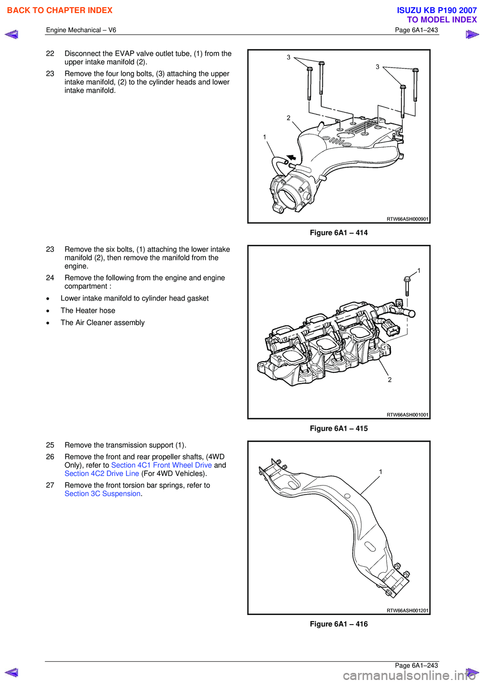
22 Disconnect the EVAP valve outlet tube, (1) from the
upper intake manifold (2).
23 Remove the four long bolts, (3) attaching the upper intake manifold, (2) to the cylinder heads and lower
intake manifold.
Figure 6A1 – 414
23 Remove the six bolts, (1) attaching the lower intake manifold (2), then remove the manifold from the
engine.
24 Remove the following from the engine and engine compartment :
• Lower intake manifold to cylinder head gasket
• The Heater hose
• The Air Cleaner assembly
Figure 6A1 – 415
25 Remove the transmission support (1).
26 Remove the front and rear propeller shafts, (4WD Only), refer to Section 4C1 Front Wheel Drive and
Section 4C2 Drive Line (For 4WD Vehicles).
27 Remove the front torsion bar springs, refer to Section 3C Suspension .
Figure 6A1 – 416
BACK TO CHAPTER INDEX
TO MODEL INDEX
ISUZU KB P190 2007
Page 3061 of 6020
Engine Mechanical – V6 Page 6A1–284
Page 6A1–284
Crankshaft and Main Bearing Visual Inspection
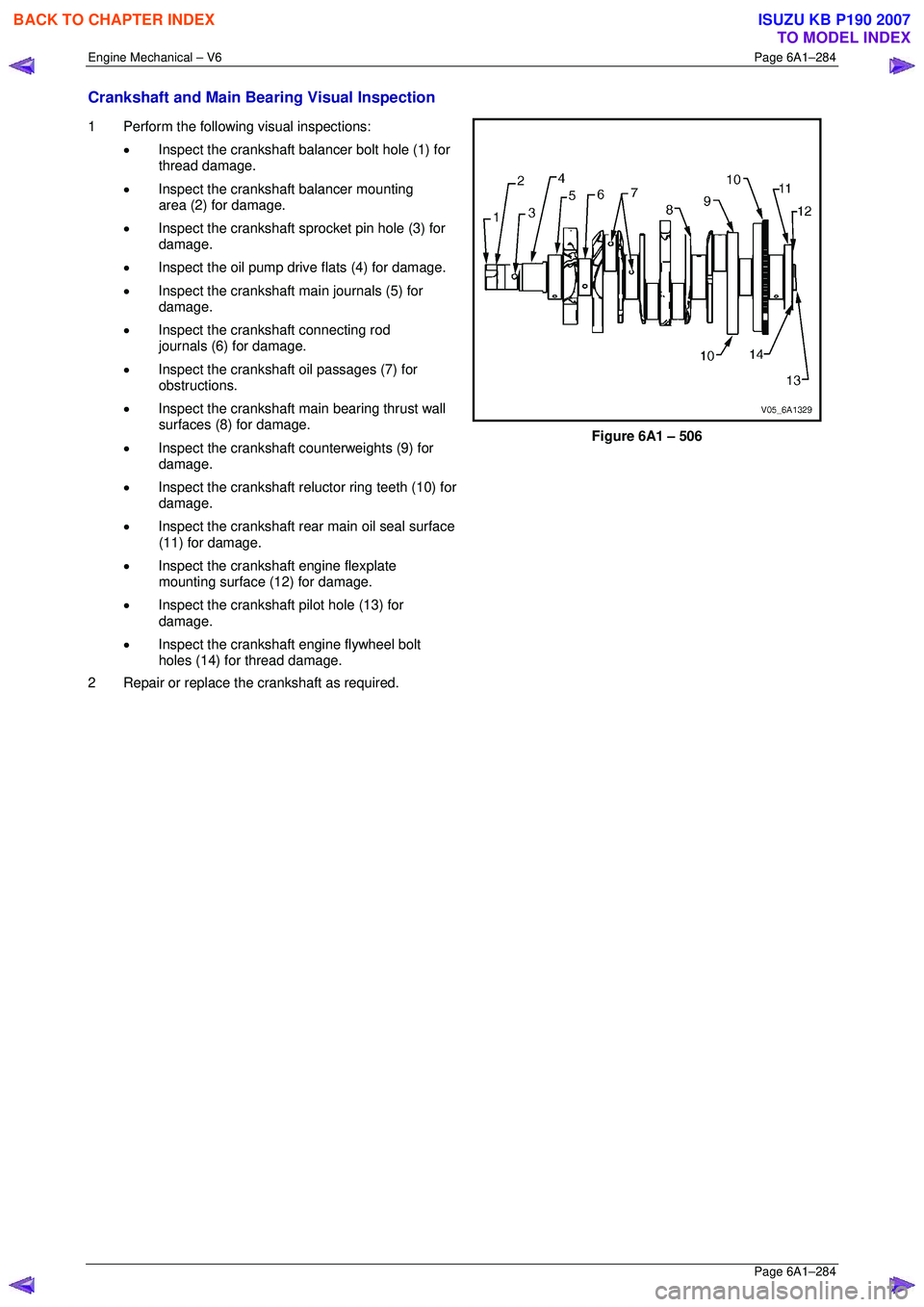
1 Perform the following visual inspections:
• Inspect the crankshaft balancer bolt hole (1) for
thread damage.
• Inspect the crankshaft balancer mounting
area (2) for damage.
• Inspect the crankshaft sprocket pin hole (3) for
damage.
• Inspect the oil pump drive flats (4) for damage.
• Inspect the crankshaft main journals (5) for
damage.
• Inspect the crankshaft connecting rod
journals (6) for damage.
• Inspect the crankshaft oil passages (7) for
obstructions.
• Inspect the crankshaft main bearing thrust wall
surfaces (8) for damage.
• Inspect the crankshaft counterweights (9) for
damage.
• Inspect the crankshaft reluctor ring teeth (10) for
damage.
• Inspect the crankshaft rear main oil seal surface
(11) for damage.
• Inspect the crankshaft engine flexplate
mounting surface (12) for damage.
• Inspect the crankshaft pilot hole (13) for
damage.
• Inspect the crankshaft engine flywheel bolt
holes (14) for thread damage.
2 Repair or replace the crankshaft as required.
Figure 6A1 – 506
BACK TO CHAPTER INDEX
TO MODEL INDEX
ISUZU KB P190 2007
Page 3222 of 6020
Fuel System – V6 Page 6C – 20
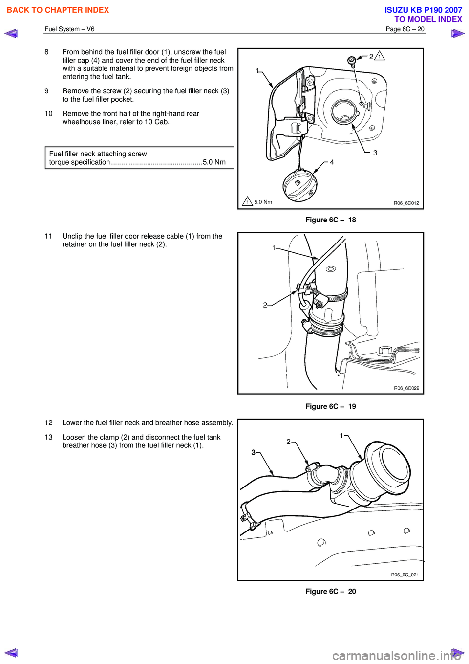
8 From behind the fuel filler door (1), unscrew the fuel
filler cap (4) and cover the end of the fuel filler neck
with a suitable material to prevent foreign objects from
entering the fuel tank.
9 Remove the screw (2) securing the fuel filler neck (3) to the fuel filler pocket.
10 Remove the front half of the right-hand rear wheelhouse liner, refer to 10 Cab.
Fuel filler neck attaching screw
torque specification ..............................................5.0 Nm
Figure 6C – 18
11 Unclip the fuel filler door release cable (1) from the retainer on the fuel filler neck (2).
Figure 6C – 19
12 Lower the fuel filler neck and breather hose assembly.
13 Loosen the clamp (2) and disconnect the fuel tank breather hose (3) from the fuel filler neck (1).
Figure 6C – 20
BACK TO CHAPTER INDEX
TO MODEL INDEX
ISUZU KB P190 2007
Page 3224 of 6020
Fuel System – V6 Page 6C – 22
Reinstall
Reinstallation of the fuel tank is the reverse of the removal procedure, noting the following:
1 Lift the fuel tank into position reinserting the fuel tank inlet and breather hoses into the body opening. Raise the fuel tank into place and rest the front of the tank on the crossmember.
2 Replace the fuel pump electrical connector, be sure to engage the locking tab.
3 Fit the fuel tank mounting straps in the following order, refer to Figure 6C – 17, a Loosely reattach the rear fuel tank mounting strap and bolt (8 & 9), refer to Figure 6C – 17.
b Loosely attach the front mounting strap and bolt (1 & 2), refer to Figure 6C – 17.
c Ensure that the fuel tank is located in the correct position then,
d Tighten the rear mounting strap bolt (8), Figure 6C – 17.
e Tighten the front mounting strap bolt (1), Figure 6C – 17.
4 Tighten all fuel tank mounting strap bolts to the correct torque specification.
Fuel tank mounting strap bolts
torque specification ............................................68.0 Nm
Install the fuel filter with the flow arrow on its
body pointing in the same direction as the
fuel flow to the front of the vehicle.
5 Install the disconnected quick-connect fittings to the fuel supply line at the front of the fuel tank and the evaporative line quick-connect fitting at the rear of the fuel tank. Refer to 4.1 Fuel Lines And Quick Connect Fittings, for the
correct component routeing.
6 Lower the vehicle to a comfortable working height and reinstall the clamp (1) to the fuel filler neck and reconnect the rubber fuel tank inlet hose (2) and tighten the clamp, refer to Figure 6C – 21.
7 Reinstall the fuel tank breather hose (3) to the fuel filler neck (1) and tighten the clamp (2), refer to Figure 6C – 20.
8 Clip the fuel filler door release cable (1) to the retainer on the fuel filler neck (2), refer to Figure 6C – 19.
9 Locate the fuel filler neck (3) to the filler pocket and attach with the securing screw (2), remove the cover material from the fuel filler neck inlet and refit the fuel filler cap (4), refer to Figure 6C – 18.
10 Reinstall the front half of the right-hand rear wheelhouse liner, refer to 10 Cab.
11 Before starting the vehicle, perform a fuel system leak test, refer to 3.3 Fuel Leak Test.
BACK TO CHAPTER INDEX
TO MODEL INDEX
ISUZU KB P190 2007
Page 3229 of 6020
Fuel System – V6 Page 6C – 27
4.6 Evaporative Emission Control Canister
Remove
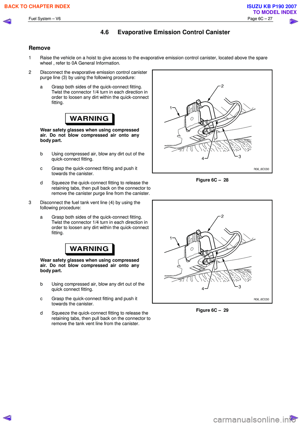
1 Raise the vehicle on a hoist to give access to the evaporative emission control canister, located above the spare
wheel , refer to 0A General Information.
2 Disconnect the evaporative emission control canister purge line (3) by using the following procedure:
a Grasp both sides of the quick-connect fitting. Twist the connector 1/4 turn in each direction in
order to loosen any dirt within the quick-connect
fitting.
Wear safety glasses when using compressed
air. Do not blow compressed air onto any
body part.
b Using compressed air, blow any dirt out of the quick-connect fitting.
c Grasp the quick-connect fitting and push it towards the canister.
d Squeeze the quick-connect fitting to release the retaining tabs, then pull back on the connector to
remove the canister purge line from the canister.
Figure 6C – 28
3 Disconnect the fuel tank vent line (4) by using the following procedure:
a Grasp both sides of the quick-connect fitting. Twist the connector 1/4 turn in each direction in
order to loosen any dirt within the quick-connect
fitting.
Wear safety glasses when using compressed
air. Do not blow compressed air onto any
body part.
b Using compressed air, blow any dirt out of the quick connect fitting.
c Grasp the quick-connect fitting and push it towards the canister.
d Squeeze the quick-connect fitting to release the retaining tabs, then pull back on the connector to
remove the tank vent line from the canister.
Figure 6C – 29
BACK TO CHAPTER INDEX
TO MODEL INDEX
ISUZU KB P190 2007
Page 3262 of 6020
Engine Management – V6 – General Information Page 6C1-1–20
4.3 Barometric Pressure Sensor
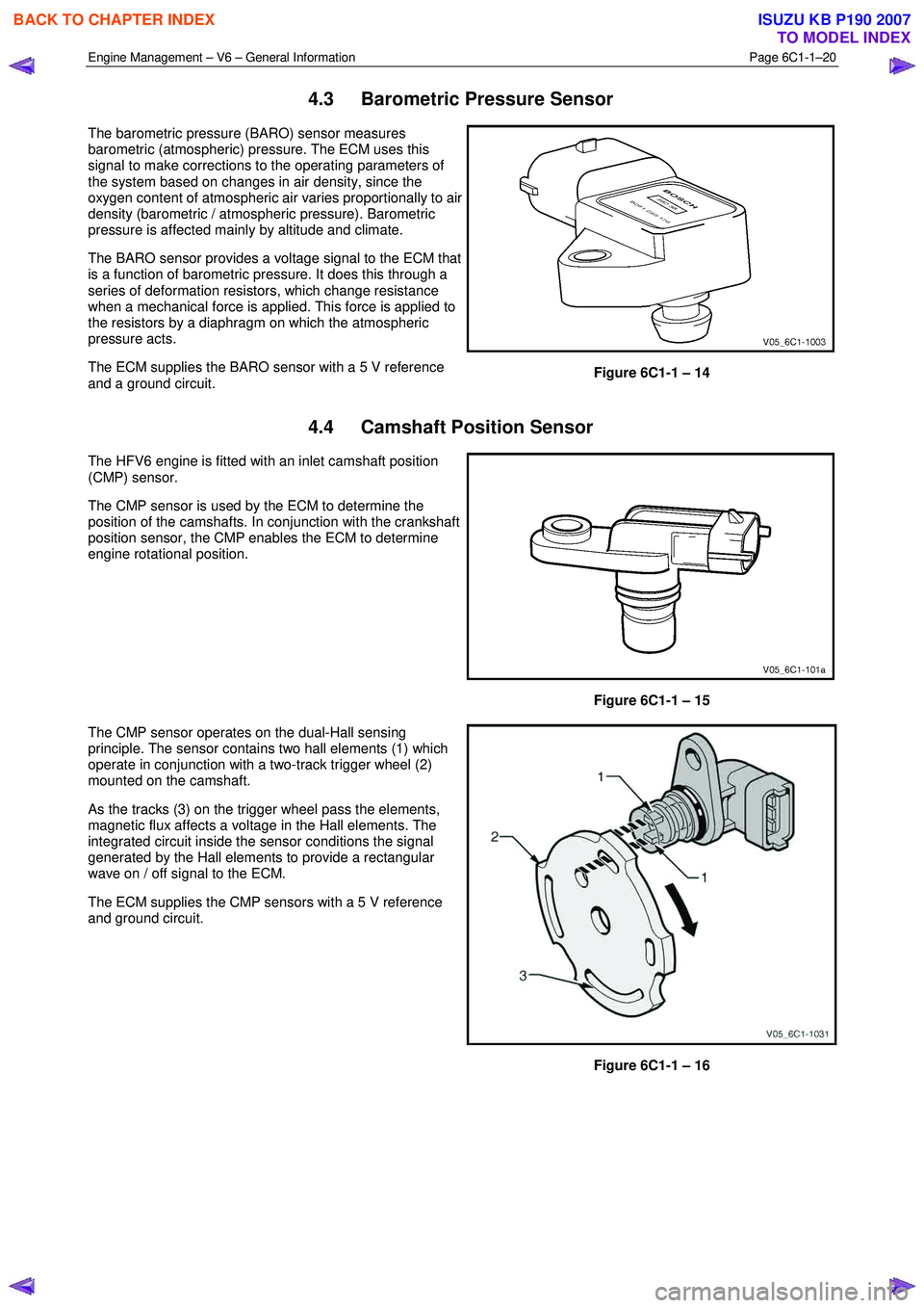
The barometric pressure (BARO) sensor measures
barometric (atmospheric) pressure. The ECM uses this
signal to make corrections to the operating parameters of
the system based on changes in air density, since the
oxygen content of atmospheric air varies proportionally to air
density (barometric / atmospheric pressure). Barometric
pressure is affected mainly by altitude and climate.
The BARO sensor provides a voltage signal to the ECM that
is a function of barometric pressure. It does this through a
series of deformation resistors, which change resistance
when a mechanical force is applied. This force is applied to
the resistors by a diaphragm on which the atmospheric
pressure acts.
The ECM supplies the BARO sensor with a 5 V reference
and a ground circuit.
Figure 6C1-1 – 14
4.4 Camshaft Position Sensor
The HFV6 engine is fitted with an inlet camshaft position
(CMP) sensor.
The CMP sensor is used by the ECM to determine the
position of the camshafts. In conjunction with the crankshaft
position sensor, the CMP enables the ECM to determine
engine rotational position.
Figure 6C1-1 – 15
The CMP sensor operates on the dual-Hall sensing
principle. The sensor contains two hall elements (1) which
operate in conjunction with a two-track trigger wheel (2)
mounted on the camshaft.
As the tracks (3) on the trigger wheel pass the elements,
magnetic flux affects a voltage in the Hall elements. The
integrated circuit inside the sensor conditions the signal
generated by the Hall elements to provide a rectangular
wave on / off signal to the ECM.
The ECM supplies the CMP sensors with a 5 V reference
and ground circuit.
Figure 6C1-1 – 16
BACK TO CHAPTER INDEX
TO MODEL INDEX
ISUZU KB P190 2007
Page 3263 of 6020
Engine Management – V6 – General Information Page 6C1-1–21
4.5 Crankshaft Position Sensor
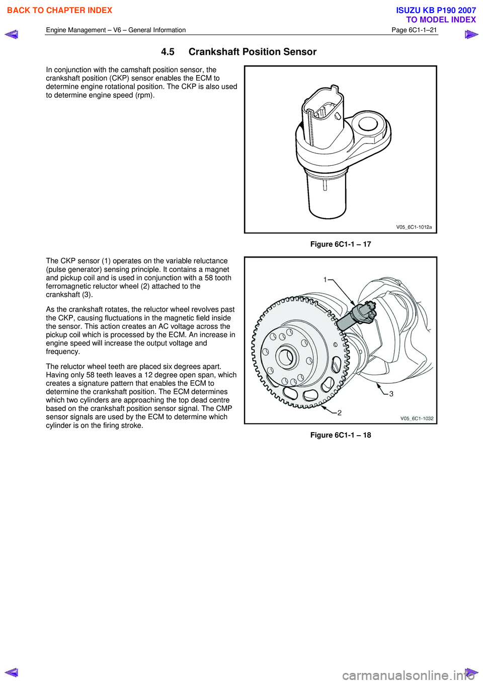
In conjunction with the camshaft position sensor, the
crankshaft position (CKP) sensor enables the ECM to
determine engine rotational position. The CKP is also used
to determine engine speed (rpm).
Figure 6C1-1 – 17
The CKP sensor (1) operates on the variable reluctance
(pulse generator) sensing principle. It contains a magnet
and pickup coil and is used in conjunction with a 58 tooth
ferromagnetic reluctor wheel (2) attached to the
crankshaft (3).
As the crankshaft rotates, the reluctor wheel revolves past
the CKP, causing fluctuations in the magnetic field inside
the sensor. This action creates an AC voltage across the
pickup coil which is processed by the ECM. An increase in
engine speed will increase the output voltage and
frequency.
The reluctor wheel teeth are placed six degrees apart.
Having only 58 teeth leaves a 12 degree open span, which
creates a signature pattern that enables the ECM to
determine the crankshaft position. The ECM determines
which two cylinders are approaching the top dead centre
based on the crankshaft position sensor signal. The CMP
sensor signals are used by the ECM to determine which
cylinder is on the firing stroke.
Figure 6C1-1 – 18
BACK TO CHAPTER INDEX
TO MODEL INDEX
ISUZU KB P190 2007