2007 ISUZU KB P190 wheel
[x] Cancel search: wheelPage 3612 of 6020
Starting System – V6 Page 6D1-2–4
• Clarify a procedure,
• Present additional information for accomplishing a procedure,
• Give insight into the reasons for performing a procedure in the recommended manner, and / or
Present information that gives the technician the benefit of past experience in accomplishing a procedure with greater
ease.
1.2 Components
Starting System Components
The main components of the starting system are:
• battery,
• wiring,
• ignition switch,
• theft deterrent engine crank inhibitor (a function of the theft deterrent system),
• park / neutral and back-up switch (on vehicles with 4 speed automatic transmission),
• engine control module (ECM),
• start relay,
• solenoid switch, and
• starter motor.
Starter Motor and Solenoid Switch Components
Solenoid Switch
The solenoid switch is used to activate the DC motor and has two windings; the pull-in winding and the hold-in winding.
The pull-in winding has heavier wire and is grounded through the DC motor winding and brushes. The hold-in winding is
grounded through the solenoid casing.
Planetary Drive Train
The planetary drive train consists of an internally toothed ring gear and three planetary gear wheels, which rotate on
sleeve bearings on the planetary drive shaft. The ring gear is keyed into the drive-end housing and is made from
high-grade polyamide with mineral additives.
W hen the starter motor operates, the armature turns the planetary gears inside the fixed planetary ring gear. This drives
the planetary shaft at a reduced speed ratio which turns the drive assembly. A fork lever in the drive-end housing forces
the drive assembly forward to engage with the flexplate / flywheel ring gear on the engine and transmit cranking torque.
An internal clutch allows the drive assembly pinion gear to rotate freely when the engine starts. This prevents the
armature from being driven at excessive speed by the engine.
Armature
The armature shaft is supported at each end by oil absorbent, sintered metal bushes; one in the commutator end shield
and one in the planetary drive shaft. The front end of the armature has a gear profile. This meshes with the three
planetary gear wheels. These in turn, mesh with the internal teeth of the ring gear.
Brushes
A brush plate supports four commutator brushes. This plate is fixed to the commutator end shield with two retaining
screws. Two negative brushes are grounded to the pole housing. The two positive brushes are insulated from the pole
housing and connected to the solenoid switch M terminal, refer to Figure 6D1-2 – 1.
BACK TO CHAPTER INDEX
TO MODEL INDEX
ISUZU KB P190 2007
Page 3614 of 6020
Starting System – V6 Page 6D1-2–6
Sequence of Operation
1 W hen the ignition switch is turned to the START position, a signal is also sent to the ECM to request the engine to
crank.
• For automatic vehicles the transmission must be in either park (P) or neutral (N) for the ECM to allow
cranking to commence.
• The ECM will only allow cranking if the battery voltage is above the minimum battery voltage threshold value,
refer to 6C1-1 Engine Management – V6 – General Information for further information.
2 The ECM operates the start relay which provides power to the pull-in winding of the start solenoid.
3 Current flow to the pull-in winding develops powerful magnetism which pulls in the solenoid switch plunger.
4 The plunger closes the switch contacts connecting battery voltage to the DC motor and pivots the fork lever to engage the drive assembly to the flexplate / flywheel ring gear. Closing the solenoid switch contacts deactivates the
pull-in winding, the hold-in winding remains active.
5 W ith the solenoid switch contacts closed, current flows from the battery through the DC motor, which rotates the armature at high speed and provides cranking torque.
BACK TO CHAPTER INDEX
TO MODEL INDEX
ISUZU KB P190 2007
Page 3624 of 6020
Starting System – V6 Page 6D1-2–16
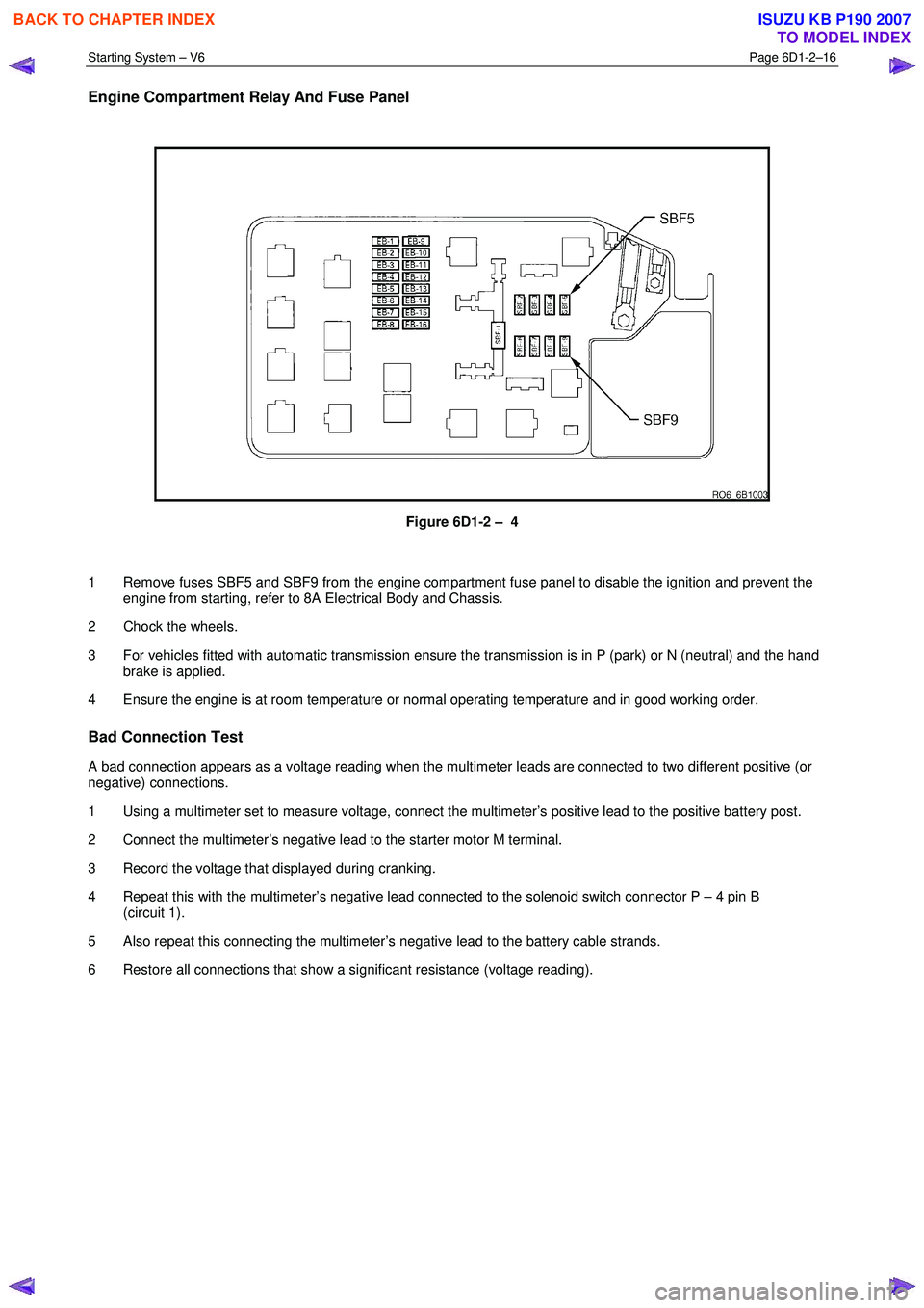
Engine Compartment Relay And Fuse Panel
Figure 6D1-2 – 4
1 Remove fuses SBF5 and SBF9 from the engine compartment fuse panel to disable the ignition and prevent the engine from starting, refer to 8A Electrical Body and Chassis.
2 Chock the wheels.
3 For vehicles fitted with automatic transmission ensure the transmission is in P (park) or N (neutral) and the hand brake is applied.
4 Ensure the engine is at room temperature or normal operating temperature and in good working order.
Bad Connection Test
A bad connection appears as a voltage reading when the multimeter leads are connected to two different positive (or
negative) connections.
1 Using a multimeter set to measure voltage, connect the multimeter’s positive lead to the positive battery post.
2 Connect the multimeter’s negative lead to the starter motor M terminal.
3 Record the voltage that displayed during cranking.
4 Repeat this with the multimeter’s negative lead connected to the solenoid switch connector P – 4 pin B (circuit 1).
5 Also repeat this connecting the multimeter’s negative lead to the battery cable strands.
6 Restore all connections that show a significant resistance (voltage reading).
BACK TO CHAPTER INDEX
TO MODEL INDEX
ISUZU KB P190 2007
Page 3714 of 6020
Powertrain Interface Module – V6 Page 6E1–53
9.13 DTC P0500, P0502 or P0503 – Vehicle
Speed Sensor Signal Malfunction
DTC Descriptors
This diagnostic procedure supports the following DTC’s:
• DTC P0500 – Vehicle speed sensor open circuit, short circuit to battery voltage, short circuit to ground, or
undefined error
• DTC P0502 – Vehicle speed sensor sensor low voltage
• DTC P0503 – Vehicle speed sensor intermittant fault
Circuit Description
The PIM applies the ground to the vehicle speed sensor (VSS) low reference circuit.
The VSS in conjunction with the 40X reluctor wheel generates an AC signal voltage. The amplitude and frequency of the
signal generated is proportional to the vehicle speed. The PIM uses this signal from the VSS signal circuit to determine
the vehicle speed.
A VSS DTC sets if the PIM detects a fault condition in the VSS signal circuit.
Conditions for Running the DTC
DTC P0500
Runs continuously once the following condition is met:
• The ignition is on and the vehicle is stationary.
DTC P0502
Runs continuously once the following condition is met:
• The first time the ignition is on and the vehicle starts to move from the stationary position.
DTC P0503
Runs continuously once the following condition is met:
• The ignition is on and the vehicle is mobile.
Conditions for Setting the DTC
DTC P0500
W hen the PIM reads back the 15 consecutive readings within 0.5 seconds.
DTC P0502
If the reading is >9.1 Km/Hr the DTC will be set.
DTC P0503
The DTC will set when the sensor detects an occurance of 15 times within 0.5 seconds.
Conditions for Clearing DTC
The DTC’s will clear on the next ignition cycle.
Additional Information
• Refer to 7B1_Manual Transmission.
BACK TO CHAPTER INDEX
TO MODEL INDEX
ISUZU KB P190 2007
Page 3715 of 6020
Powertrain Interface Module – V6 Page 6E1–54
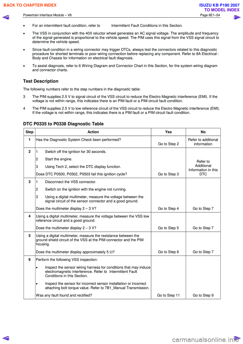
• For an intermittent fault condition, refer to Intermittent Fault Conditions in this Section.
• The VSS in conjunction with the 40X reluctor wheel generates an AC signal voltage. The amplitude and frequency
of the signal generated is proportional to the vehicle speed. The PIM uses this signal from the VSS signal circuit to
determine the vehicle speed.
• Since fault condition in a wiring connector may trigger DTCs, always test the connectors related to this diagnostic
procedure for shorted terminals or poor wiring connection before replacing any component. Refer to 8A Electrical -
Body and Chassis for information on electrical fault diagnosis.
• To assist diagnosis, refer to 6 W iring Diagram and Connector Chart in this Section, for the system wiring diagram
and connector charts.
Test Description
The following numbers refer to the step numbers in the diagnostic table:
3 The PIM supplies 2.5 V to signal circuit of the VSS circuit to reduce the Electro Magnetic interference (EMI). If the voltage is not within range, this indicates there is an PIM fault or a PIM circuit fault condition.
4 The PIM supplies 2.5 V to low reference circuit of the VSS circuit to reduce the Electro Magnetic interference (EMI). If the voltage is not within range, this indicates there is a PIM fault or a PIM circuit fault condition.
DTC P0335 to P0338 Diagnostic Table
Step Action Yes No
1
Has the Diagnostic System Check been performed?
Go to Step 2 Refer to additional
information
2 1 Switch off the ignition for 30 seconds.
2 Start the engine.
3 Using Tech 2, select the DTC display function.
Does DTC P0500, P0502, P0503 fail this ignition cycle? Go to Step 3 Refer to
Additional
Information in this DTC
3 1 Disconnect the VSS connector.
2 Switch on the ignition with the engine not running.
3 Using a digital multimeter, measure the voltage between the signal circuit of the sensor connector and a good ground.
Does the multimeter display 2 – 3 V? Go to Step 4 Go to Step 7
4 Using a digital multimeter, measure the voltage between the VSS low
reference circuit and a good ground.
Does the multimeter display 2 – 3 V? Go to Step 5 Go to Step 7
5 Using a digital multimeter, measure the resistance between the
ground shield circuit of the VSS at the PIM connector and the PIM
housing.
Does the multimeter display approximately 5 Ω? Go to Step 6 Go to Step 7
6
Perform the following VSS inspection:
• Inspect the sensor wiring harness for conditions that may induce
electromagnetic interference. Refer to Intermittent Fault
Conditions in this Section.
• Inspect the sensor for incorrect sensor installation or incorrect
attaching bolt torque value. Refer to 7B1_Manual Transmission.
W as any fault found and rectified? Go to Step 11 Go to Step 9
BACK TO CHAPTER INDEX
TO MODEL INDEX
ISUZU KB P190 2007
Page 3772 of 6020
Automatic Transmission – 4L60E – General Information Page 7C1–12
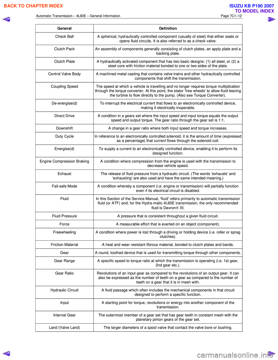
General Definition
Check Ball A spherical, hydraulically controlled component (usually of steel) that either seals or
opens fluid circuits. It is also referred to as a check valve.
Clutch Pack An assembly of components generally consisting of clutch plates, an apply plate and a
backing plate.
Clutch Plate A hydraulically activated component that has two basic designs: (1) all steel, or (2) a
steel core with friction material bonded to one or two sides of the plate.
Control Valve Body A machined metal casting that contains valve trains and other hydraulically controlled components that shift the transmission.
Coupling Speed The speed at which a vehicle is travelling and no longer requires torque multiplication through the torque converter. At this point, the stator 'free wheels' to allow fluid leaving
the turbine to flow directly to the pump. (Also see Torque Converter).
De-energise(d) To interrupt the electrical current that flows to an electronically controlled device,
making it electrically inoperable.
Direct Drive A condition in a gears set where the input speed and input torque equals the output
speed and output torque. The gear ratio through the gear set is 1:1.
Downshift A change in a gear ratio where both input speed and torque increases.
Duty Cycle In reference to an electronically controlled solenoid, it is the amount of time (expressed
as a percentage) that current flows through the solenoid coil.
Energise(d) To supply a current to an electronically controlled device, enabling it to perform its
designed function.
Engine Compression Braking A condition where compression from the engine is used with the transmission to decrease vehicle speed.
Exhaust The release of fluid pressure from a hydraulic circuit. (The words 'exhausts' and
'exhausting' are also used and have the same intended meaning.)
Fail-safe Mode A condition whereby a component (i.e. engine or transmission) will partially function even if its electrical circuit is disabled.
Fluid In this Section of the Service Manual, 'fluid' refers primarily to automatic transmission
fluid (or ATF) and, for the Hydra-matic 4L60E transmission, the only recommended
fluid is Dexron
III.
Fluid Pressure A pressure that is consistent throughout a given fluid circuit.
Force A measurable effort that is exerted on an object (component).
Freewheeling A condition where power is lost through a driving or holding device (i.e. roller or sprag
clutches).
Friction Material A heat and wear resistant fibrous material, bonded to clutch plates and bands.
Gear A round, toothed device that is used for transmitting torque through other components.
Gear Range A specific speed to torque ratio at which the transmission is operating (i.e. 1st gear,
2nd gear etc.).
Gear Ratio Revolutions of an input gear as compared to the revolutions of an output gear. It can
also be expressed as the number of teeth on a gear as compared to the number of
teeth on a gear that it is in mesh with.
Hydraulic Circuit A fluid passage which often includes the mechanical components in that circuit
designed to perform a specific function.
Input A starting point for torque, revolutions or energy into another component of the
transmission.
Internal Gear The outermost member of a gear set that has gear teeth in constant mesh with the
planetary pinion gears of the gear set.
Land (Valve Land) The larger diameters of a spool valve that contact the valve bore or bushing.
BACK TO CHAPTER INDEX
TO MODEL INDEX
ISUZU KB P190 2007
Page 3773 of 6020
Automatic Transmission – 4L60E – General Information Page 7C1–13
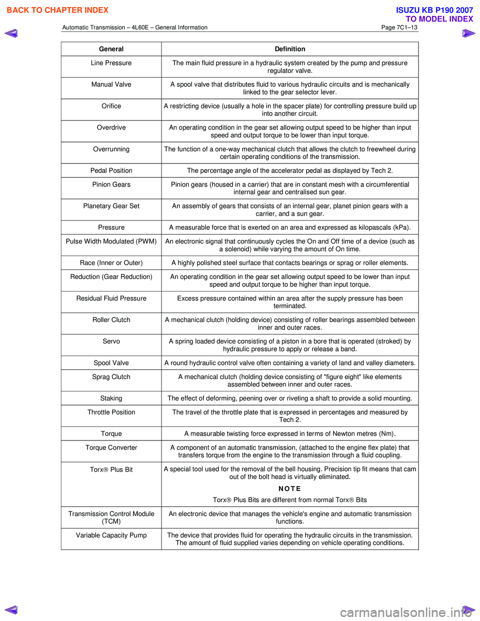
General Definition
Line Pressure The main fluid pressure in a hydraulic system created by the pump and pressure
regulator valve.
Manual Valve A spool valve that distributes fluid to various hydraulic circuits and is mechanically
linked to the gear selector lever.
Orifice A restricting device (usually a hole in the spacer plate) for controlling pressure build up
into another circuit.
Overdrive An operating condition in the gear set allowing output speed to be higher than input
speed and output torque to be lower than input torque.
Overrunning The function of a one-way mechanical clutch that allows the clutch to freewheel during certain operating conditions of the transmission.
Pedal Position The percentage angle of the accelerator pedal as displayed by Tech 2.
Pinion Gears Pinion gears (housed in a carrier) that are in constant mesh with a circumferential
internal gear and centralised sun gear.
Planetary Gear Set An assembly of gears that consists of an internal gear, planet pinion gears with a carrier, and a sun gear.
Pressure A measurable force that is exerted on an area and expressed as kilopascals (kPa).
Pulse Width Modulated (PW M) An electronic signal that continuously cycles the On and Off time of a device (such as
a solenoid) while varying the amount of On time.
Race (Inner or Outer) A highly polished steel surface that contacts bearings or sprag or roller elements.
Reduction (Gear Reduction) An operating condition in the gear set allowing output speed to be lower than input speed and output torque to be higher than input torque.
Residual Fluid Pressure Excess pressure contained within an area after the supply pressure has been terminated.
Roller Clutch A mechanical clutch (holding device) consisting of roller bearings assembled between inner and outer races.
Servo A spring loaded device consisting of a piston in a bore that is operated (stroked) by
hydraulic pressure to apply or release a band.
Spool Valve A round hydraulic control valve often containing a variety of land and valley diameters.
Sprag Clutch A mechanical clutch (holding device consisting of "figure eight" like elements
assembled between inner and outer races.
Staking The effect of deforming, peening over or riveting a shaft to provide a solid mounting.
Throttle Position The travel of the throttle plate that is expressed in percentages and measured by
Tech 2.
Torque A measurable twisting force expressed in terms of Newton metres (Nm).
Torque Converter A component of an automatic transmission, (attached to the engine flex plate) that
transfers torque from the engine to the transmission through a fluid coupling.
Torx Plus Bit A special tool used for the removal of the bell housing. Precision tip fit means that cam
out of the bolt head is virtually eliminated.
NOTE
Torx
Plus Bits are different from normal Torx
Bits
Transmission Control Module
(TCM) An electronic device that manages the vehicle's engine and automatic transmission
functions.
Variable Capacity Pump The device that provides fluid for operating the hydraulic circuits in the transmission. The amount of fluid supplied varies depending on vehicle operating conditions.
BACK TO CHAPTER INDEX
TO MODEL INDEX
ISUZU KB P190 2007
Page 3774 of 6020
Automatic Transmission – 4L60E – General Information Page 7C1–14
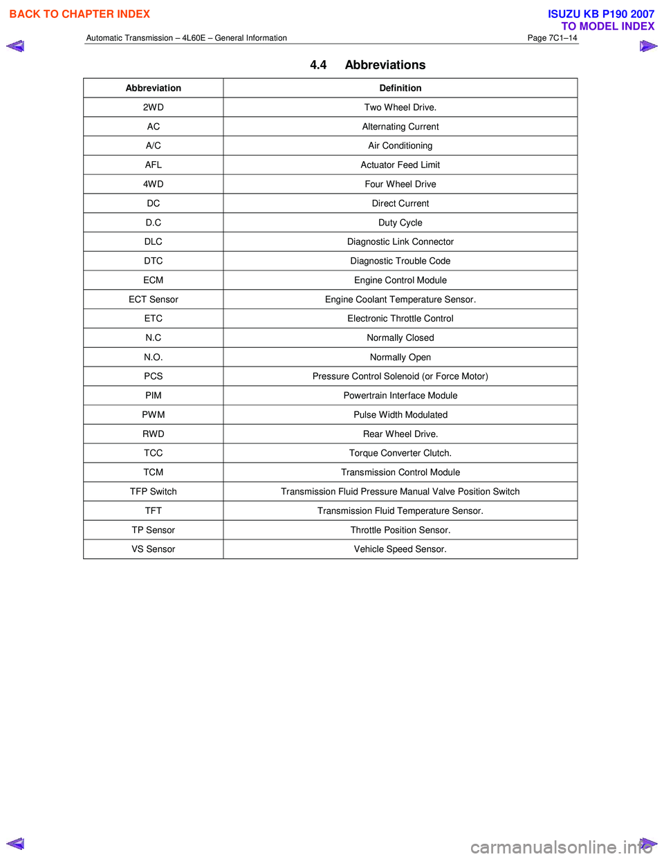
4.4 Abbreviations
Abbreviation Definition
2W D Two W heel Drive.
AC Alternating Current
A/C Air Conditioning
AFL Actuator Feed Limit
4W D Four W heel Drive
DC Direct Current
D.C Duty Cycle
DLC Diagnostic Link Connector
DTC Diagnostic Trouble Code
ECM Engine Control Module
ECT Sensor Engine Coolant Temperature Sensor.
ETC Electronic Throttle Control
N.C Normally Closed
N.O. Normally Open
PCS Pressure Control Solenoid (or Force Motor)
PIM Powertrain Interface Module
PW M Pulse W idth Modulated
RWD Rear Wheel Drive.
TCC Torque Converter Clutch.
TCM Transmission Control Module
TFP Switch Transmission Fluid Pressure Manual Valve Position Switch
TFT Transmission Fluid Temperature Sensor.
TP Sensor Throttle Position Sensor.
VS Sensor Vehicle Speed Sensor.
BACK TO CHAPTER INDEX
TO MODEL INDEX
ISUZU KB P190 2007