2007 ISUZU KB P190 wheel
[x] Cancel search: wheelPage 4114 of 6020

ON-VEHICLE SERVICE (AW30–40LE) 7A3-29
Install or Connect
1. Install the shift cable toward the inside of the cabin
from the bottom of the vehicle.
2. Push the shift cable into the select lever base.
3. Connect the shift cable to the select lever.
4. Fix the shift cable to the bracket.
Install the clip on the marking of shift cable.
5. Check that the select lever is in the “N” position.
6. Check that the transmission is in the “N” position.
249R300002
7. Slide the cover in the direction shown by the arrow
(1).
8. Use an ordinary screwdriver to move the lock piece
from the position indicated by the arrow (2). Continue
to move the lock piece until the adjuster position
begins to change.
P1010012
9. Connect the shift cable to the manual shaft select
lever at the transmission side.
10. Insert the lock piece to the adjuster (cable length
adjustment).
11. Slide the cover on the adjuster and secure lock
piece.
P1010016-2
11. Press the select lever knob button 5 times.
Then check that the select lever moves smoothly to each of its positions.
13. Check that the shift position indicated by the select
lever and the actual shift position are the same.
14. Install the front console and rear console.
15. Connect the negative battery cable.
16. Remove the wheel blocks.
BACK TO CHAPTER INDEX
TO MODEL INDEX
ISUZU KB P190 2007
Page 4286 of 6020
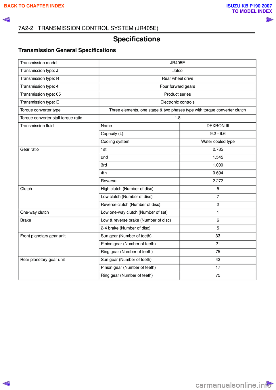
7A2-2 TRANSMISSION CONTROL SYSTEM (JR405E)
Specifications
Transmission General Specifications
Transmission modelJR405E
Transmission type: J Jatco
Transmission type: R Rear wheel drive
Transmission type: 4 Four forward gears
Transmission type: 05 Product series
Transmission type: E Electronic controls
Torque converter type Three elements, one stage & two phases type with torque converter clutch
Torque converter stall torque ratio 1.8
Transmission fluid Name DEXRON III
Capacity (L) 9.2 - 9.6
Cooling system Water cooled type
Gear ratio 1st 2.785
2nd 1.545
3rd 1.000
4th 0.694
Reverse 2.272
Clutch High clutch (Number of disc) 5
Low clutch (Number of disc) 7
Reverse clutch (Number of disc) 2
One-way clutch Low one-way clutch (Number of set) 1
Brake Low & reverse brake (Number of disc) 6
2-4 brake (Number of disc) 5
Front planetary gear unit Sun gear (Number of teeth) 33
Pinion gear (Number of teeth) 21
Ring gear (Number of teeth) 75
Rear planetary gear unit Sun gear (Number of teeth) 42
Pinion gear (Number of teeth) 17
Ring gear (Number of teeth) 75
BACK TO CHAPTER INDEX
TO MODEL INDEX
ISUZU KB P190 2007
Page 4308 of 6020
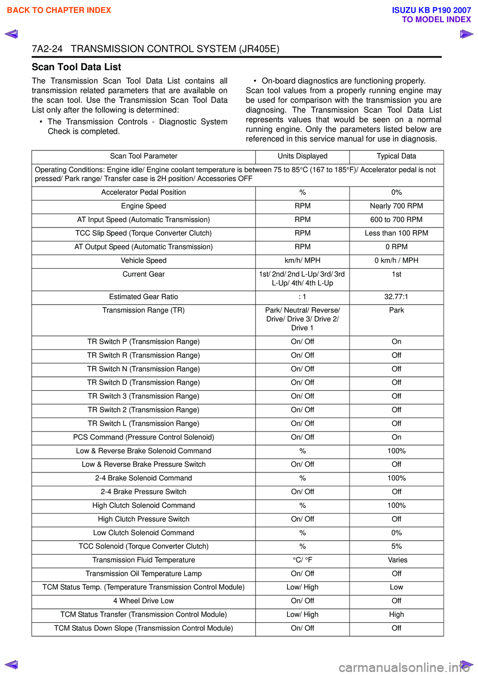
7A2-24 TRANSMISSION CONTROL SYSTEM (JR405E)
Scan Tool Data List
The Transmission Scan Tool Data List contains all
transmission related parameters that are available on
the scan tool. Use the Transmission Scan Tool Data
List only after the following is determined:
• The Transmission Controls - Diagnostic System Check is completed. • On-board diagnostics are functioning properly.
Scan tool values from a properly running engine may
be used for comparison with the transmission you are
diagnosing. The Transmission Scan Tool Data List
represents values that would be seen on a normal
running engine. Only the parameters listed below are
referenced in this service manual for use in diagnosis.
Scan Tool Parameter Units DisplayedTypical Data
Operating Conditions: Engine idle/ Engine coolant temperature is between 75 to 85 °C (167 to 185 °F)/ Accelerator pedal is not
pressed/ Park range/ Transfer case is 2H position/ Accessories OFF
Accelerator Pedal Position %0%
Engine Speed RPMNearly 700 RPM
AT Input Speed (Automatic Transmission) RPM600 to 700 RPM
TCC Slip Speed (Torque Converter Clutch) RPMLess than 100 RPM
AT Output Speed (Automatic Transmission) RPM0 RPM
Vehicle Speed km/h/ MPH0 km/h / MPH
Current Gear 1st/ 2nd/ 2nd L-Up/ 3rd/ 3rd
L-Up/ 4th/ 4th L-Up 1st
Estimated Gear Ratio : 132.77:1
Transmission Range (TR) Park/ Neutral/ Reverse/
Drive/ Drive 3/ Drive 2/ Drive 1 Park
TR Switch P (Transmission Range) On/ OffOn
TR Switch R (Transmission Range) On/ OffOff
TR Switch N (Transmission Range) On/ OffOff
TR Switch D (Transmission Range) On/ OffOff
TR Switch 3 (Transmission Range) On/ OffOff
TR Switch 2 (Transmission Range) On/ OffOff
TR Switch L (Transmission Range) On/ OffOff
PCS Command (Pressure Control Solenoid) On/ OffOn
Low & Reverse Brake Solenoid Command %100%
Low & Reverse Brake Pressure Switch On/ OffOff
2-4 Brake Solenoid Command %100%
2-4 Brake Pressure Switch On/ OffOff
High Clutch Solenoid Command %100%
High Clutch Pressure Switch On/ OffOff
Low Clutch Solenoid Command %0%
TCC Solenoid (Torque Converter Clutch) %5%
Transmission Fluid Temperature °C/ °F V arie s
Transmission Oil Temperature Lamp On/ OffOff
TCM Status Temp. (Temperature Transmission Control Module) Low/ HighLow
4 Wheel Drive Low On/ OffOff
TCM Status Transfer (Transmission Control Module) Low/ HighHigh
TCM Status Down Slope (Transmission Control Module) On/ OffOff
BACK TO CHAPTER INDEX
TO MODEL INDEX
ISUZU KB P190 2007
Page 4310 of 6020
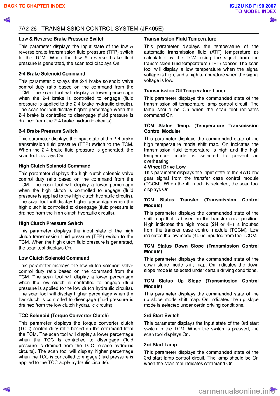
7A2-26 TRANSMISSION CONTROL SYSTEM (JR405E)
Low & Reverse Brake Pressure Switch
This parameter displays the input state of the low &
reverse brake transmission fluid pressure (TFP) switch
to the TCM. When the low & reverse brake fluid
pressure is generated, the scan tool displays On.
2-4 Brake Solenoid Command
This parameter displays the 2-4 brake solenoid valve
control duty ratio based on the command from the
TCM. The scan tool will display a lower percentage
when the 2-4 brake is controlled to engage (fluid
pressure is applied to the 2-4 brake hydraulic circuits).
The scan tool will display higher percentage when the
2-4 brake is controlled to disengage (fluid pressure is
drained from the 2-4 brake hydraulic circuits).
2-4 Brake Pressure Switch
This parameter displays the input state of the 2-4 brake
transmission fluid pressure (TFP) switch to the TCM.
When the 2-4 brake fluid pressure is generated, the
scan tool displays On.
High Clutch Solenoid Command
This parameter displays the high clutch solenoid valve
control duty ratio based on the command from the
TCM. The scan tool will display a lower percentage
when the high clutch is controlled to engage (fluid
pressure is applied to the high clutch hydraulic circuits).
The scan tool will display higher percentage when the
high clutch is controlled to disengage (fluid pressure is
drained from the high clutch hydraulic circuits).
High Clutch Pressure Switch
This parameter displays the input state of the high
clutch transmission fluid pressure (TFP) switch to the
TCM. When the high clutch fluid pressure is generated,
the scan tool displays On.
Low Clutch Solenoid Command
This parameter displays the low clutch solenoid valve
control duty ratio based on the command from the
TCM. The scan tool will display a lower percentage
when the low clutch is controlled to engage (fluid
pressure is applied to the low clutch hydraulic circuits).
The scan tool will display higher percentage when the
low clutch is controlled to disengage (fluid pressure is
drained from the low clutch hydraulic circuits).
TCC Solenoid (Torque Converter Clutch)
This parameter displays the torque converter clutch
(TCC) control duty ratio based on the command from
the TCM. The scan tool will display a lower percentage
when the TCC is controlled to disengage (fluid
pressure is drained from the TCC release hydraulic
circuits). The scan tool will display higher percentage
when the TCC is controlled to engage (fluid pressure is
applied to the TCC apply hydraulic circuits). Transmission Fluid Temperature
This parameter displays the temperature of the
automatic transmission fluid (ATF) temperature as
calculated by the TCM using the signal from the
transmission fluid temperature (TFT) sensor. The scan
tool will display a low temperature when the signal
voltage is high, and a high temperature when the signal
voltage is low.
Transmission Oil Temperature Lamp
This parameter displays the commanded state of the
transmission oil temperature lamp control circuit. The
lamp should be On when the scan tool indicates
command On.
TCM Status Temp. (Temperature Transmission
Control Module)
This parameter displays the commanded state of the
high temperature mode shift map. On indicates the
transmission fluid temperature is high and the high
temperature mode is selected to prevent an
overheating.
4 Wheel Drive Low
This parameter displays the input state of the 4WD low
gear signal from the transfer case control module
(TCCM). When the 4L mode is selected, the scan tool
displays On.
TCM Status Transfer (Transmission Control
Module)
This parameter displays the commanded state of the
shift map that is based on the transfer case position.
High indicates the high mode (2H or 4H) is inputted
from the transfer case control module (TCCM). Low
indicates the low mode (4L) is inputted from the TCCM.
TCM Status Down Slope (Transmission Control
Module)
This parameter displays the commanded state of the
down slope mode shift map. On indicates the down
slope mode is selected under certain driving conditions.
TCM Status Up Slope (Transmission Control
Module)
This parameter displays the commanded state of the
up slope mode shift map. On indicates the up slope
mode is selected under certin driving conditions.
3rd Start Switch
This parameter displays the input state of the 3rd start
switch to the TCM. When the switch is pressed, the
scan tool displays On.
3rd Start Lamp
This parameter displays the commanded state of the
3rd start lamp control circuit. The lamp should be On
when the scan tool indicates command On.
BACK TO CHAPTER INDEX
TO MODEL INDEX
ISUZU KB P190 2007
Page 4328 of 6020
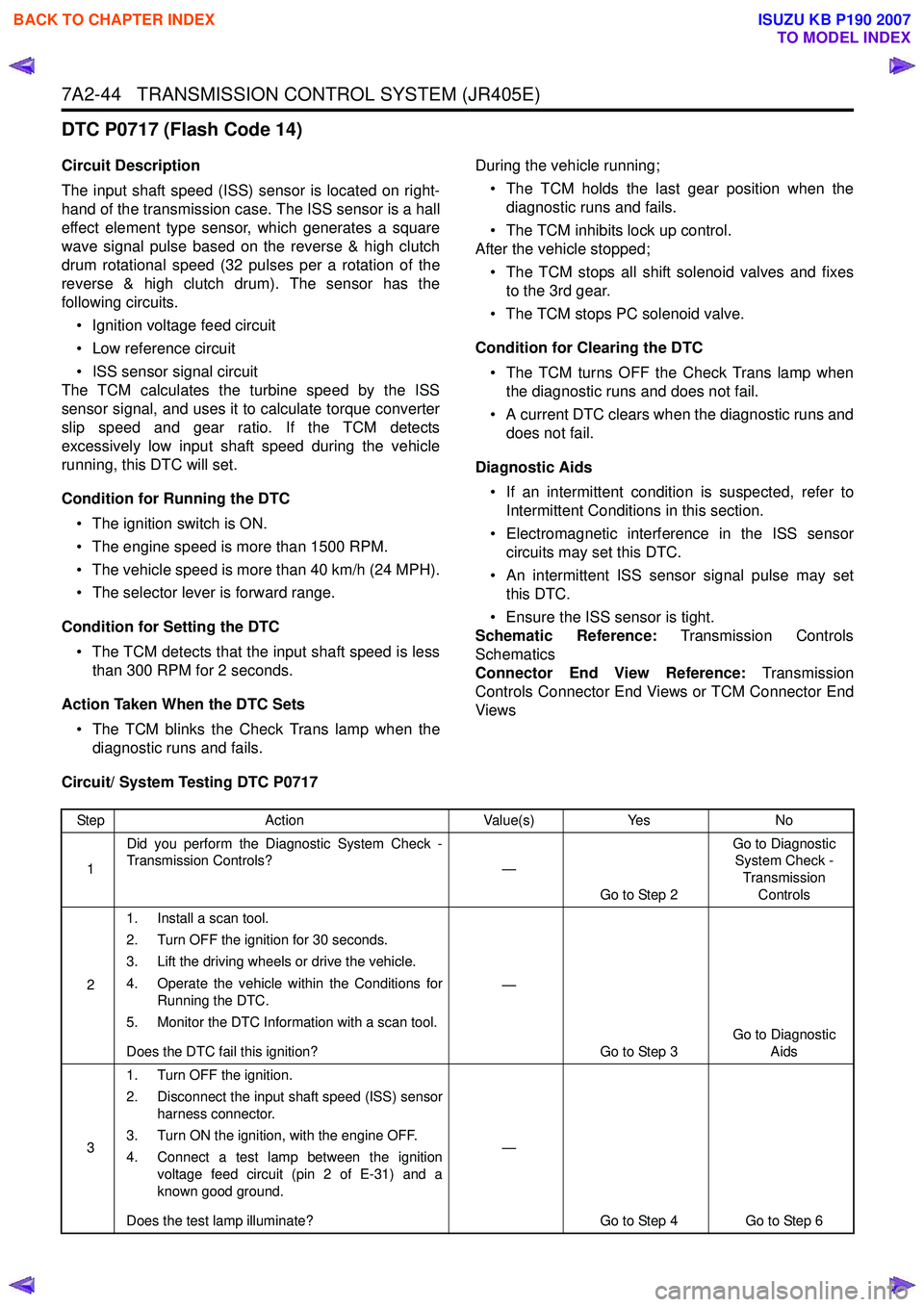
7A2-44 TRANSMISSION CONTROL SYSTEM (JR405E)
DTC P0717 (Flash Code 14)
Circuit Description
The input shaft speed (ISS) sensor is located on right-
hand of the transmission case. The ISS sensor is a hall
effect element type sensor, which generates a square
wave signal pulse based on the reverse & high clutch
drum rotational speed (32 pulses per a rotation of the
reverse & high clutch drum). The sensor has the
following circuits.
• Ignition voltage feed circuit
• Low reference circuit
• ISS sensor signal circuit
The TCM calculates the turbine speed by the ISS
sensor signal, and uses it to calculate torque converter
slip speed and gear ratio. If the TCM detects
excessively low input shaft speed during the vehicle
running, this DTC will set.
Condition for Running the DTC • The ignition switch is ON.
• The engine speed is more than 1500 RPM.
• The vehicle speed is more than 40 km/h (24 MPH).
• The selector lever is forward range.
Condition for Setting the DTC • The TCM detects that the input shaft speed is less than 300 RPM for 2 seconds.
Action Taken When the DTC Sets • The TCM blinks the Check Trans lamp when the diagnostic runs and fails. During the vehicle running;
• The TCM holds the last gear position when the diagnostic runs and fails.
• The TCM inhibits lock up control.
After the vehicle stopped;
• The TCM stops all shift solenoid valves and fixes to the 3rd gear.
• The TCM stops PC solenoid valve.
Condition for Clearing the DTC • The TCM turns OFF the Check Trans lamp when the diagnostic runs and does not fail.
• A current DTC clears when the diagnostic runs and does not fail.
Diagnostic Aids • If an intermittent condition is suspected, refer to Intermittent Conditions in this section.
• Electromagnetic interference in the ISS sensor circuits may set this DTC.
• An intermittent ISS sensor signal pulse may set this DTC.
• Ensure the ISS sensor is tight.
Schematic Reference: Transmission Controls
Schematics
Connector End View Reference: Transmission
Controls Connector End Views or TCM Connector End
Views
Circuit/ System Testing DTC P0717
Step Action Value(s)Yes No
1 Did you perform the Diagnostic System Check -
Transmission Controls? —
Go to Step 2 Go to Diagnostic
System Check -
Transmission Controls
2 1. Install a scan tool.
2. Turn OFF the ignition for 30 seconds.
3. Lift the driving wheels or drive the vehicle.
4. Operate the vehicle within the Conditions for Running the DTC.
5. Monitor the DTC Information with a scan tool.
Does the DTC fail this ignition? —
Go to Step 3 Go to Diagnostic
Aids
3 1. Turn OFF the ignition.
2. Disconnect the input shaft speed (ISS) sensor harness connector.
3. Turn ON the ignition, with the engine OFF.
4. Connect a test lamp between the ignition voltage feed circuit (pin 2 of E-31) and a
known good ground.
Does the test lamp illuminate? —
Go to Step 4 Go to Step 6
BACK TO CHAPTER INDEX
TO MODEL INDEX
ISUZU KB P190 2007
Page 4342 of 6020
7A2-58 TRANSMISSION CONTROL SYSTEM (JR405E)
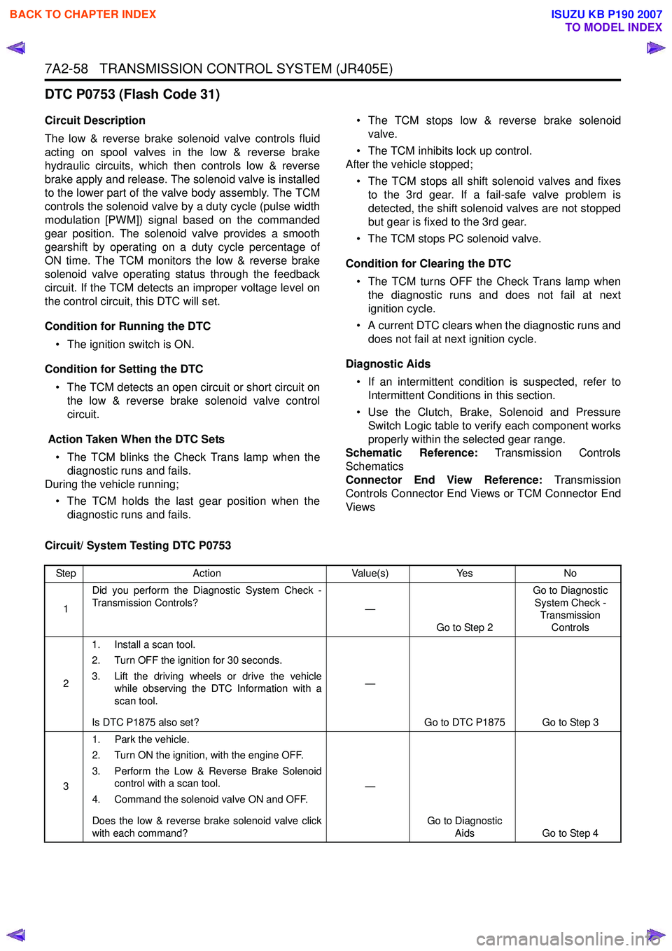
DTC P0753 (Flash Code 31)
Circuit Description
The low & reverse brake solenoid valve controls fluid
acting on spool valves in the low & reverse brake
hydraulic circuits, which then controls low & reverse
brake apply and release. The solenoid valve is installed
to the lower part of the valve body assembly. The TCM
controls the solenoid valve by a duty cycle (pulse width
modulation [PWM]) signal based on the commanded
gear position. The solenoid valve provides a smooth
gearshift by operating on a duty cycle percentage of
ON time. The TCM monitors the low & reverse brake
solenoid valve operating status through the feedback
circuit. If the TCM detects an improper voltage level on
the control circuit, this DTC will set.
Condition for Running the DTC • The ignition switch is ON.
Condition for Setting the DTC • The TCM detects an open circuit or short circuit on the low & reverse brake solenoid valve control
circuit.
Action Taken When the DTC Sets • The TCM blinks the Check Trans lamp when the diagnostic runs and fails.
During the vehicle running;
• The TCM holds the last gear position when the diagnostic runs and fails. • The TCM stops low & reverse brake solenoid
valve.
• The TCM inhibits lock up control.
After the vehicle stopped;
• The TCM stops all shift solenoid valves and fixes to the 3rd gear. If a fail-safe valve problem is
detected, the shift solenoid valves are not stopped
but gear is fixed to the 3rd gear.
• The TCM stops PC solenoid valve.
Condition for Clearing the DTC • The TCM turns OFF the Check Trans lamp when the diagnostic runs and does not fail at next
ignition cycle.
• A current DTC clears when the diagnostic runs and does not fail at next ignition cycle.
Diagnostic Aids • If an intermittent condition is suspected, refer to Intermittent Conditions in this section.
• Use the Clutch, Brake, Solenoid and Pressure Switch Logic table to verify each component works
properly within the selected gear range.
Schematic Reference: Transmission Controls
Schematics
Connector End View Reference: Transmission
Controls Connector End Views or TCM Connector End
Views
Circuit/ System Testing DTC P0753
Step Action Value(s)Yes No
1 Did you perform the Diagnostic System Check -
Transmission Controls? —
Go to Step 2 Go to Diagnostic
System Check - Transmission Controls
2 1. Install a scan tool.
2. Turn OFF the ignition for 30 seconds.
3. Lift the driving wheels or drive the vehicle while observing the DTC Information with a
scan tool.
Is DTC P1875 also set? —
Go to DTC P1875 Go to Step 3
3 1. Park the vehicle.
2. Turn ON the ignition, with the engine OFF.
3. Perform the Low & Reverse Brake Solenoid control with a scan tool.
4. Command the solenoid valve ON and OFF.
Does the low & reverse brake solenoid valve click
with each command? —
Go to Diagnostic Aids Go to Step 4
BACK TO CHAPTER INDEX
TO MODEL INDEX
ISUZU KB P190 2007
Page 4344 of 6020
7A2-60 TRANSMISSION CONTROL SYSTEM (JR405E)
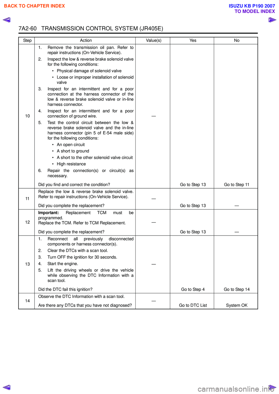
101. Remove the transmission oil pan. Refer to
repair instructions (On-Vehicle Service).
2. Inspect the low & reverse brake solenoid valve for the following conditions:
• Physical damage of solenoid valve
• Loose or improper installation of solenoid valve
3. Inspect for an intermittent and for a poor connection at the harness connector of the
low & reverse brake solenoid valve or in-line
harness connector.
4. Inspect for an intermittent and for a poor connection of ground wire.
5. Test the control circuit between the low & reverse brake solenoid valve and the in-line
harness connector (pin 5 of E-54 male side)
for the following conditions:
• An open circuit
• A short to ground
• A short to the other solenoid valve circuit
• High resistance
6. Repair the connection(s) or circuit(s) as necessary.
Did you find and correct the condition? —
Go to Step 13 Go to Step 11
11 Replace the low & reverse brake solenoid valve.
Refer to repair instructions (On-Vehicle Service).
Did you complete the replacement? —
Go to Step 13 —
12 Important:
Replacement TCM must be
programmed.
Replace the TCM. Refer to TCM Replacement.
Did you complete the replacement? —
Go to Step 13 —
13 1. Reconnect all previously disconnected
components or harness connector(s).
2. Clear the DTCs with a scan tool.
3. Turn OFF the ignition for 30 seconds.
4. Start the engine.
5. Lift the driving wheels or drive the vehicle while observing the DTC Information with a
scan tool.
Did the DTC fail this ignition? —
Go to Step 4 Go to Step 14
14 Observe the DTC Information with a scan tool.
Are there any DTCs that you have not diagnosed? —
Go to DTC List System OK
Step
Action Value(s)Yes No
BACK TO CHAPTER INDEX
TO MODEL INDEX
ISUZU KB P190 2007
Page 4345 of 6020
TRANSMISSION CONTROL SYSTEM (JR405E) 7A2-61
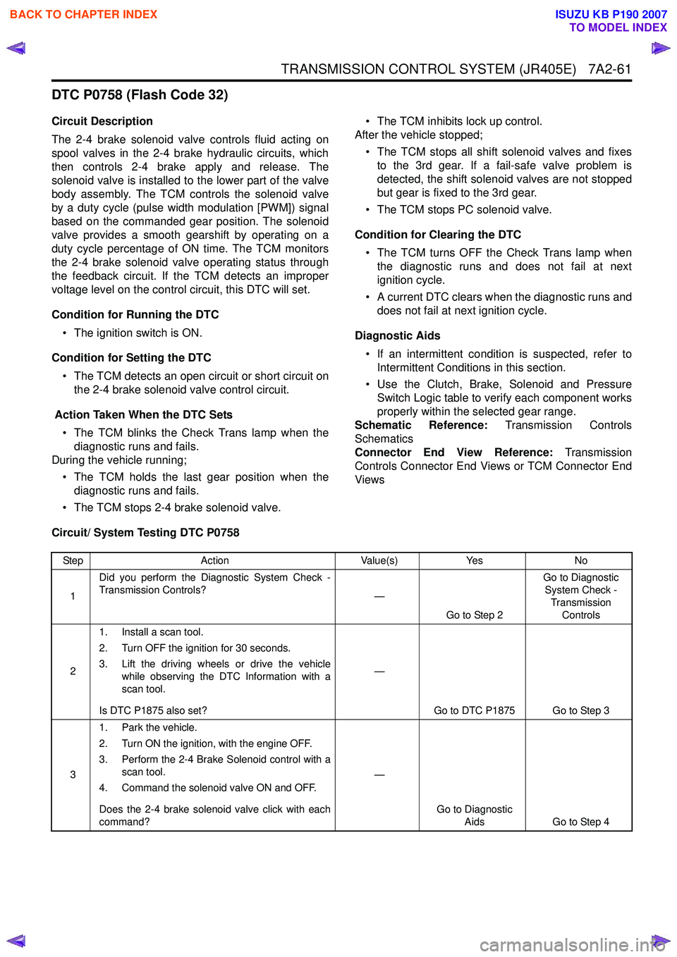
DTC P0758 (Flash Code 32)
Circuit Description
The 2-4 brake solenoid valve controls fluid acting on
spool valves in the 2-4 brake hydraulic circuits, which
then controls 2-4 brake apply and release. The
solenoid valve is installed to the lower part of the valve
body assembly. The TCM controls the solenoid valve
by a duty cycle (pulse width modulation [PWM]) signal
based on the commanded gear position. The solenoid
valve provides a smooth gearshift by operating on a
duty cycle percentage of ON time. The TCM monitors
the 2-4 brake solenoid valve operating status through
the feedback circuit. If the TCM detects an improper
voltage level on the control circuit, this DTC will set.
Condition for Running the DTC • The ignition switch is ON.
Condition for Setting the DTC • The TCM detects an open circuit or short circuit on the 2-4 brake solenoid valve control circuit.
Action Taken When the DTC Sets • The TCM blinks the Check Trans lamp when the diagnostic runs and fails.
During the vehicle running;
• The TCM holds the last gear position when the diagnostic runs and fails.
• The TCM stops 2-4 brake solenoid valve. • The TCM inhibits lock up control.
After the vehicle stopped;
• The TCM stops all shift solenoid valves and fixes to the 3rd gear. If a fail-safe valve problem is
detected, the shift solenoid valves are not stopped
but gear is fixed to the 3rd gear.
• The TCM stops PC solenoid valve.
Condition for Clearing the DTC • The TCM turns OFF the Check Trans lamp when the diagnostic runs and does not fail at next
ignition cycle.
• A current DTC clears when the diagnostic runs and does not fail at next ignition cycle.
Diagnostic Aids • If an intermittent condition is suspected, refer to Intermittent Conditions in this section.
• Use the Clutch, Brake, Solenoid and Pressure Switch Logic table to verify each component works
properly within the selected gear range.
Schematic Reference: Transmission Controls
Schematics
Connector End View Reference: Transmission
Controls Connector End Views or TCM Connector End
Views
Circuit/ System Testing DTC P0758
Step Action Value(s)Yes No
1 Did you perform the Diagnostic System Check -
Transmission Controls? —
Go to Step 2 Go to Diagnostic
System Check - Transmission Controls
2 1. Install a scan tool.
2. Turn OFF the ignition for 30 seconds.
3. Lift the driving wheels or drive the vehicle while observing the DTC Information with a
scan tool.
Is DTC P1875 also set? —
Go to DTC P1875 Go to Step 3
3 1. Park the vehicle.
2. Turn ON the ignition, with the engine OFF.
3. Perform the 2-4 Brake Solenoid control with a scan tool.
4. Command the solenoid valve ON and OFF.
Does the 2-4 brake solenoid valve click with each
command? —
Go to Diagnostic Aids Go to Step 4
BACK TO CHAPTER INDEX
TO MODEL INDEX
ISUZU KB P190 2007