Page 1994 of 6020
EXHAUST SYSTEM (4JK1/4JJ1) 6F-9
Removal
1. Drain the coolant.
2. Remove the intercooler.
3. Remove the heat protector.
4. Disconnect the water hoses from the EGR coole
r
water pipes.
5. Remove the EGR cooler.
Installation (Standard Output)
1. Gasket
2. EGR Cooler
3. Nuts and Bolts
RTW 56FSH000201
• Temporary tightening order
1 – 2 – 4 – 5 - 3
• Fully tightening order
4 – 5 – 1 – 2 - 3
Tighten the nuts and bolts to the specified torque.
Tightening torque: 27 N ⋅
⋅⋅
⋅
m (2.8 kg ⋅
⋅⋅
⋅
m / 20 lb ft)
4. W ater hose
5. Heat protector • Tighten the bolts to the specified torque.
Tightening torque: 10 N ⋅
⋅⋅
⋅
m (1.0 kg ⋅
⋅⋅
⋅
m / 87 lb in)
RTW 56ASH014601
6. Replenish the engine coolant.
BACK TO CHAPTER INDEX
TO MODEL INDEX
ISUZU KB P190 2007
Page 1995 of 6020
6F-10 EXHAUST SYSTEM (4JK1/4JJ1)
Installation (High Output)
1. Gasket
2. EGR Cooler
3. Nuts and Bolts
6
543
1
2
RTW 76FSH000201
• Temporary tightening order
1 →2→ 3→ 4→ 5→ 6
• Fully tightening order
3 →4→ 5→ 1→ 2→ 6
Tighten the nuts and bolts to the specified torque.
Tightening torque: Nuts and bolts 1-5: 27 N ⋅
⋅⋅
⋅
m (2.8 kg ⋅
⋅⋅
⋅
m / 20 lb ft)
Bolt 6: 52 N⋅
⋅⋅
⋅
m (5.3 kg ⋅
⋅⋅
⋅
m / 38 lb ft)
4. W ater hose
5. Heat protector • Tighten the bolts to the specified torque.
Tightening torque: 25 N ⋅
⋅⋅
⋅
m (2.5 kg ⋅
⋅⋅
⋅
m / 18 lb ft)
RTW 76FSH000101
6. Replenish the engine coolant.
BACK TO CHAPTER INDEX
TO MODEL INDEX
ISUZU KB P190 2007
Page 1996 of 6020
EXHAUST SYSTEM (4JK1/4JJ1) 6F-11
Torque Specifications (Standard Output)
RTW 56AMF002201
BACK TO CHAPTER INDEX
TO MODEL INDEX
ISUZU KB P190 2007
Page 1997 of 6020
6F-12 EXHAUST SYSTEM (4JK1/4JJ1)
Torque Specifications (High Output)
RTW 76FMF000301
BACK TO CHAPTER INDEX
TO MODEL INDEX
ISUZU KB P190 2007
Page 2003 of 6020

ENGINE DIAGNOSIS (C24SE) 6-3
3.Trouble in Fuel System Condition Possible cause Correction
Starting motor turns over and
spark occurs but engine does not
start. Fuel tank empty Fill
Water in fuel system Clean
Fuel filter clogged Replace filter
Fuel pipe clogged Clean or replace
Fuel pump defective Replace
Fuel pump circuit open Correct or replace
Evaporative Emission Control
system circuit clogged Correct or replace
Multiport Fuel Injection System
faulty Refer to "Electronic Fuel Injection"
section
4.Engine Lacks Compression
Condition Possible cause Correction
Engine lacks compression Spark plug loosely fitted or spark
plug gasket defective Tighten to specified torque or
replace gasket
Spark plug wire incorrect Connect properly or replace
Valve timing incorrect Adjust
Cylinder head gasket defective Replace gasket
Valve incorrectly seated Lap valve
Valve stem seized Replace valve and valve guide
Valve spring weakened Replace
Cylinder or piston rings worn Overhaul engine
Piston ring seized Overhaul engine.
Engine Compression Test Procedure
1. Start and run the engine until the engine
reaches normal operating temperature.
2. Turn the engine off.
3. Remove all the spark plugs.
4. Remove ignition coil fuse (15A) and disable the ignition system.
5. Remove the fuel pump relay from the relay and fuse box. 6. Engage the starter and check that the cranking
speed is approximately 300 rpm.
7. Install cylinder compression gauge into spark plug hole.
8. With the throttle valve opened fully, keep the starter engaged until the compression gauge
needle reaches the maximum level. Note the
reading.
9. Repeat the test with each cylinder. The pressure difference between the individual
cylinders should not exceed 100kPa (14.5 psi).
BACK TO CHAPTER INDEX
TO MODEL INDEX
ISUZU KB P190 2007
Page 2033 of 6020

ENGINE MECHANICAL (C24SE) 6A-19
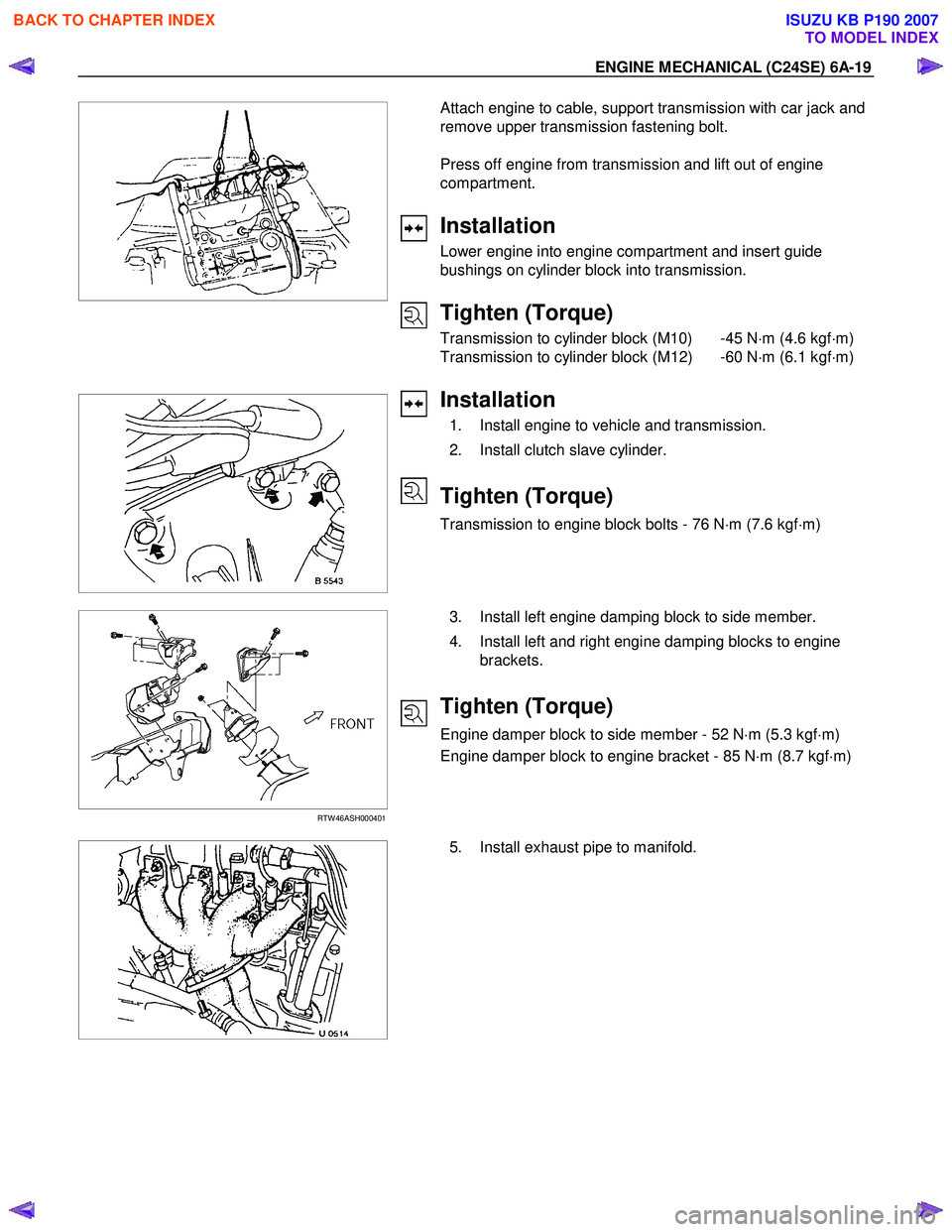
Attach engine to cable, support transmission with car jack and
remove upper transmission fastening bolt.
Press off engine from transmission and lift out of engine
compartment.
Installation
Lower engine into engine compartment and insert guide
bushings on cylinder block into transmission.
Tighten (Torque)
Transmission to cylinder block (M10) -45 N ⋅m (4.6 kgf ⋅m)
Transmission to cylinder block (M12) -60 N ⋅m (6.1 kgf ⋅m)
Installation
1. Install engine to vehicle and transmission.
2. Install clutch slave cylinder.
Tighten (Torque)
Transmission to engine block bolts - 76 N ⋅m (7.6 kgf ⋅m)
RTW 46ASH000401
3. Install left engine damping block to side member.
4. Install left and right engine damping blocks to engine brackets.
Tighten (Torque)
Engine damper block to side member - 52 N ⋅m (5.3 kgf ⋅m)
Engine damper block to engine bracket - 85 N ⋅m (8.7 kgf ⋅m)
5. Install exhaust pipe to manifold.
BACK TO CHAPTER INDEX
TO MODEL INDEX
ISUZU KB P190 2007
Page 2036 of 6020
6A-22 ENGINE MECHANICAL (C24SE)
Installation
1. Install the toothed belt to the cover.
2. Install the crankshaft pulley while counterholding on the fastening bolt of toothed belt drive gear.
3. Install the fan shroud.
Tighten(Torque)
Crankshaft pulley bolts - 20 N ⋅m (2.1 kgf ⋅m)
4. Install the fan belt
5. Install the V-belt for A/C.
6. Install the V-belt for power steering.
7. Install the fan.
8. Install the belts on the bracket for alternator.
BACK TO CHAPTER INDEX
TO MODEL INDEX
ISUZU KB P190 2007
Page 2040 of 6020

6A-26 ENGINE MECHANICAL (C24SE)
OPERATIONS ON INSTALLED ENGINE
SEALING OPERATIONS
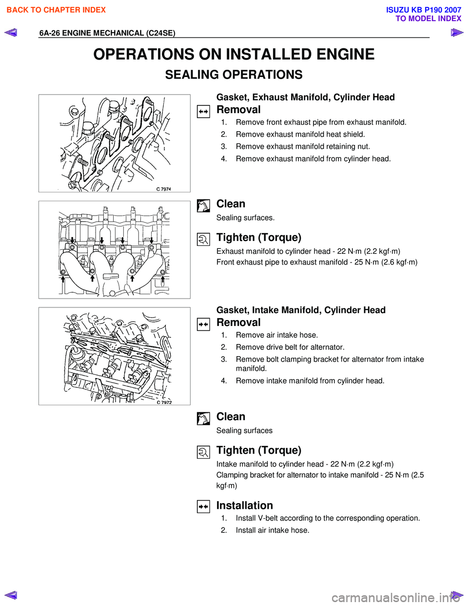
Gasket, Exhaust Manifold, Cylinder Head
Removal
1. Remove front exhaust pipe from exhaust manifold.
2. Remove exhaust manifold heat shield.
3. Remove exhaust manifold retaining nut.
4. Remove exhaust manifold from cylinder head.
Clean
Sealing surfaces.
Tighten (Torque)
Exhaust manifold to cylinder head - 22 N ⋅m (2.2 kgf ⋅m)
Front exhaust pipe to exhaust manifold - 25 N ⋅m (2.6 kgf ⋅m)
Gasket, Intake Manifold, Cylinder Head
Removal
1. Remove air intake hose.
2. Remove drive belt for alternator.
3. Remove bolt clamping bracket for alternator from intake manifold.
4. Remove intake manifold from cylinder head.
Clean
Sealing surfaces
Tighten (Torque)
Intake manifold to cylinder head - 22 N ⋅m (2.2 kgf ⋅m)
Clamping bracket for alternator to intake manifold - 25 N ⋅m (2.5
kgf ⋅m)
Installation
1. Install V-belt according to the corresponding operation.
2. Install air intake hose.
BACK TO CHAPTER INDEX
TO MODEL INDEX
ISUZU KB P190 2007