2007 ISUZU KB P190 torque
[x] Cancel search: torquePage 1582 of 6020
FUEL SYSTEM (4JK1/4JJ1) 6C-41
Removal
Note: W hen repairs to the fuel system have been
completed, start the engine and check the fuel system
for loose connections or leakage. For the fuel system
diagnosis, see Section "Drivability and Emission".
1. Disconnect the battery ground cable.
2. Slowly loosen the fuel filler cap.
Note: Be careful that fuel does not spout out because o
f
change of pressure in the fuel tank.
Note: Cover opening of the filler neck to prevent an
y
dust entering. 3. Jack up the vehicle.
4. Disconnect the quick connector (5) of the fuel tube at the fuel cooler way.
5. Remove fuel return hose (8) from the pipe.
6. Remove fixing bolt (7) of the bracket fuel coole
r
and remove bracket fuel cooler (6).
Note: Cover the opening of the pipe to prevent any dust
and fuel leakage.
Note: For remove fuel cooler, Remove bolts (10) of the
fuel cooler and remove fuel cooler.
7. Support underneath of the fuel tank with a lifter.
8. Remove the inner liner of the wheel house at rea
r
left side.
9. Remove fixing bolt of the filler neck from the body.
10. Disconnect the quick connector (5) of the fuel tube from the fuel pipe and the evapo tube from evapo
joint connector.
Note: Cover the quick connector to prevent any dust
entering and prevent fuel leakage.
Note: Refer to "Fuel Tube/Quick Connector Fittings" in
this section when performing any repairs.
11. Remove fixing bolt (1) of the tank band and remove the tank band (2).
12. Disconnect the pump and sender connector on the fuel pump and remove the harness from the weld
clip on the fuel tank.
13. Lower the fuel tank (3).
Note: W hen lowering the fuel tank from the vehicle, do
not scratch the hoses and tubes by contact with othe
r
parts.
Installation
1. Raise the fuel tank.
Note: W hen raising the fuel tank to the vehicle, do not
scratch the hoses and tubes by contact with other parts.
2. Connect the pump and sender connector to the fuel pump and install the harness to the weld clip
on the tank.
Note: The connector must be securely connected
against the stopper.
3. Install the tank band and fasten bolt.
Torque: 68 N ⋅
⋅⋅
⋅
m (6.9 kg ⋅
⋅⋅
⋅
m /50 lb ft)
Note: The anchor of the tank band must be securely
installed to the guide hole on the frame.
4. Connect the quick connector of the fuel tube to the fuel pipe and the evapo tube from evapo joint
connector.
Note: Pull off the left checker on the fuel pipe.
Note: Refer to "Fuel Tube/Quick Connector Fittings" in
this section when performing any repairs.
5. Install the filler neck to the body with bolt.
Note: For install the fuel cooler to the bracket with bolt.
Torque: 6.5 N ⋅
⋅⋅
⋅
m (0.7 kg ⋅
⋅⋅
⋅
m /61 lb in)
6. Install the bracket to Frame with bolt. Torque: 48 N ⋅
⋅⋅
⋅
m (4.9 kg ⋅
⋅⋅
⋅
m /35 lb ft)
7. Install the fuel return hose at the fuel cooler way.
8. Install the quick connector at the fuel cooler way.
9. Install the inner liner of the wheel house at rear left side.
10. Remove lifter from the fuel tank.
11. Lower the vehicle.
12. Tighten the filler cap until at least three clicks.
13. Connect the battery ground cable.
BACK TO CHAPTER INDEX
TO MODEL INDEX
ISUZU KB P190 2007
Page 1587 of 6020
6C-46 FUEL SYSTEM (4JK1/4JJ1)
Filler Neck
Removal
1. Remove the fuel tank.
Note: Refer to "Fuel Tank" in this section. 2. Put a marking on the following points as the fille
r
neck assembly is restored.
• Each joint area of the hose (to restore axial
direction and insertion length of the hose)
• Each fasten area of the clamp (to restore axial
direction and position of the clamp)
• Each bolt in the clamp (to restore fasten length
of bolt in the clamp)
• The band clip (to restore position and fasten
length of the band clip)
Note: Cover end of each hose and pipe to prevent an
y
dust entering.
Installation
1. Align each marking and restore the following point. • Each joint area of the hose (Restore axial
direction and insertion length of the hose)
• Each fasten area of the clamp (Restore axial
direction and position of the clamp)
Tightening torque: 2.5 N·m (0.25 kg ⋅
⋅⋅
⋅
m /21.7 lb in)
Filler neck side except flat deck model.
• Each bolt in the clamp (Restore fasten length o
f
bolt in the clamp)
Tightening torque: 2.5 N·m (0.25 kg ⋅
⋅⋅
⋅
m /21.7 lb in)
Filler neck side except flat deck model.
• The band clip (Restore position and fasten
length of the band clip)
2. Install the fuel tank.
Note: Refer to "Fuel Tank" in this section.
BACK TO CHAPTER INDEX
TO MODEL INDEX
ISUZU KB P190 2007
Page 1589 of 6020
ENGINE ELECTRICAL (4JK1/4JJ1) 6D-1
SECTION 6D
ENGINE ELECTRICAL
TABLE OF CONTENTS
Charging System ................................................ 6D-2
Servicing Cautions .......................................... 6D-2
Important Generator Components and
Function.......................................................... 6D-2
Troubleshooting .............................................. 6D-5
Diagnosis......................................................... 6D-7
Specifications .................................................. 6D-8
Unit Se rv ic ing (4 JJ 1) ....................................... .... ..6D -9
Disassembly .................................................... 6D-10
Inspection and Repair ..................................... 6D-11 Rotor Assembly ........................................... 6D-11
Stator Coil .................................................... 6D-12
Brushes ....................................................... 6D-12
Rectifier ....................................................... 6D-13
Regulator Assembly..................................... 6D-13
Measuring Procedure .................................. 6D-13
Reassembly..................................................... 6D-14
Final Assembly ................................................ 6D-14
Starter Motor ...................................................... 6D-15 Starting Circuit Diagram .................................. 6D-15
Removal and Installation ................................. 6D-15 Important Operations – Removal................. 6D-15
Important Operations – Installation.............. 6D-15
Disassembly .................................................... 6D-16 Disassembly Steps ...................................... 6D-16
Important Operations ................................... 6D-17
Inspection and Repair ..................................... 6D-20 Armature ...................................................... 6D-20
Yoke............................................................. 6D-21
Brush and Brush Holder .............................. 6D-22
Overrunning Clutch...................................... 6D-22
Bearing ........................................................ 6D-23
Reassembly..................................................... 6D-24 Reassembly Steps ....................................... 6D-24
Important Operations ................................... 6D-25
Inspection After Assembly ........................... 6D-26
Magnetic Switch .............................................. 6D-27
Torque Specifications...................................... 6D-28
Pre-Heating System ........................................... 6D-29 Inspection and Repair ..................................... 6D-29 Visual Check................................................ 6D-29
Glow Relay .................................................. 6D-29
Glow Plug .................................................... 6D-29
BACK TO CHAPTER INDEX
TO MODEL INDEX
ISUZU KB P190 2007
Page 1602 of 6020
6D-14 ENGINE ELECTRICAL (4JK1/4JJ1)
Reassembly
Follow the disassembly steps in reverse order to
reassemble the generator. Pay close attention to the
items below.
• Be very careful not to reverse battery polarity.
Reversed battery polarity will destroy the rectifie
r
diodes.
• Do not ground the generator B-terminal. Heat and
fire damage to the harness will result.
• If using a fast charge procedure, be sure to
disconnect the battery positive cable. If you do not,
the rectifier diodes will be exposed to high positive
voltage that will destroy them.
• Be very careful to reassemble the parts to thei
r
original positions. Particular care must be taken
with insulated parts.
• Carefully clean all insulated parts so that they are
completely free of oil and/or grease.
• Be sure that B-terminal twist-type stoppers (round
terminal) are securely inserted before tightening
the nuts.
Final Assembly
1. Use a bench press to install the rotor and rear
cover to the front cover.
RTW 56DSH000201
2. Install the pulley to the rotor shaft and tighten the
bolt to the specified torque.
Pulley bolt torque N
⋅m (kg⋅m / lb ft)
111 (11.3 / 81.7)
RTW 56DSH000101
BACK TO CHAPTER INDEX
TO MODEL INDEX
ISUZU KB P190 2007
Page 1603 of 6020
ENGINE ELECTRICAL (4JK1/4JJ1) 6D-15
Starter Motor
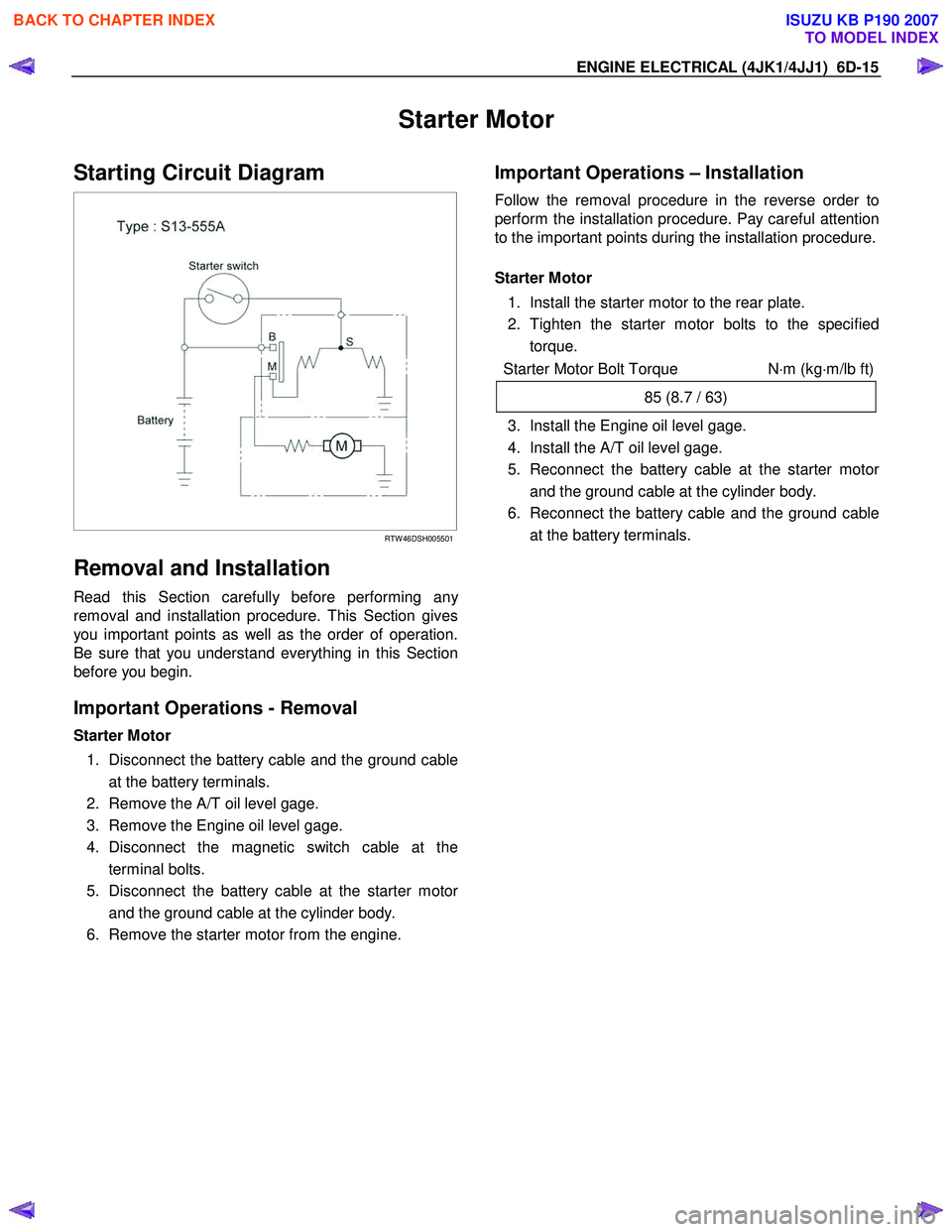
Starting Circuit Diagram
RTW 46DSH005501
Removal and Installation
Read this Section carefully before performing any
removal and installation procedure. This Section gives
you important points as well as the order of operation.
Be sure that you understand everything in this Section
before you begin.
Important Operations - Removal
Starter Motor
1. Disconnect the battery cable and the ground cable at the battery terminals.
2. Remove the A/T oil level gage.
3. Remove the Engine oil level gage.
4. Disconnect the magnetic switch cable at the terminal bolts.
5. Disconnect the battery cable at the starter moto
r
and the ground cable at the cylinder body.
6. Remove the starter motor from the engine.
Important Operations – Installation
Follow the removal procedure in the reverse order to
perform the installation procedure. Pay careful attention
to the important points during the installation procedure.
Starter Motor
1. Install the starter motor to the rear plate.
2. Tighten the starter motor bolts to the specified torque.
Starter Motor Bolt Torque N⋅m (kg ⋅m/lb ft)
85 (8.7 / 63)
3. Install the Engine oil level gage.
4. Install the A/T oil level gage.
5. Reconnect the battery cable at the starter moto
r
and the ground cable at the cylinder body.
6. Reconnect the battery cable and the ground cable at the battery terminals.
BACK TO CHAPTER INDEX
TO MODEL INDEX
ISUZU KB P190 2007
Page 1613 of 6020
ENGINE ELECTRICAL (4JK1/4JJ1) 6D-25
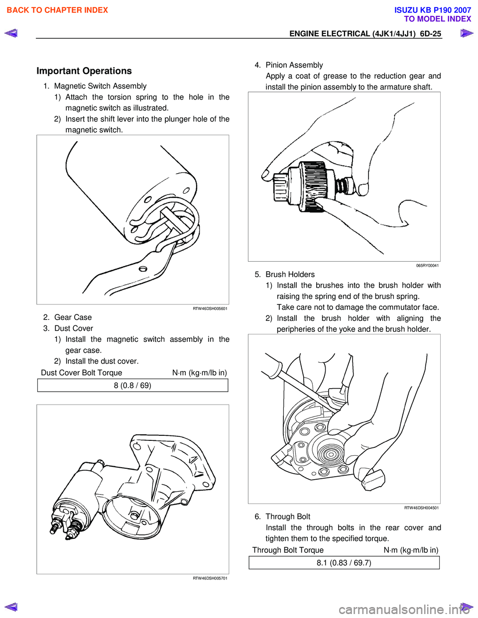
Important Operations
1. Magnetic Switch Assembly
1)
Attach the torsion spring to the hole in the
magnetic switch as illustrated.
2) Insert the shift lever into the plunger hole of the magnetic switch.
RTW 46DSH005601
2. Gear Case
3. Dust Cover 1) Install the magnetic switch assembly in the gear case.
2) Install the dust cover.
Dust Cover Bolt Torque N⋅m (kg ⋅m/lb in)
8 (0.8 / 69)
RTW 46DSH005701
4. Pinion Assembly
Apply a coat of grease to the reduction gear and
install the pinion assembly to the armature shaft.
065RY00041
5. Brush Holders
1) Install the brushes into the brush holder with raising the spring end of the brush spring.
Take care not to damage the commutator face.
2) Install the brush holder with aligning the peripheries of the yoke and the brush holder.
RTW 46DSH004501
6. Through Bolt
Install the through bolts in the rear cover and tighten them to the specified torque.
Through Bolt Torque N⋅m (kg ⋅m/lb in)
8.1 (0.83 / 69.7)
BACK TO CHAPTER INDEX
TO MODEL INDEX
ISUZU KB P190 2007
Page 1614 of 6020
6D-26 ENGINE ELECTRICAL (4JK1/4JJ1)
065RY00044
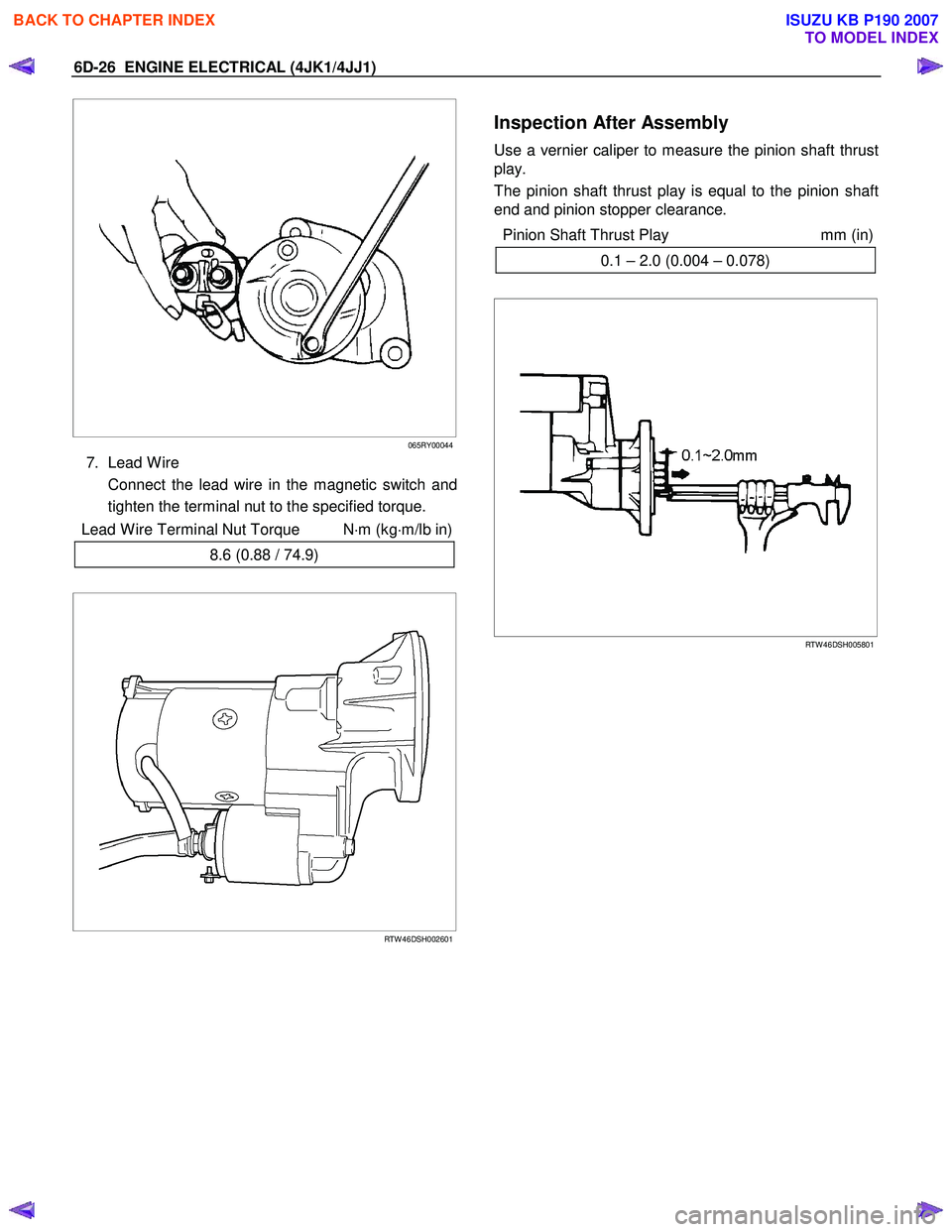
7. Lead W ire
Connect the lead wire in the magnetic switch and tighten the terminal nut to the specified torque.
Lead W ire Terminal Nut Torque N ⋅m (kg ⋅m/lb in)
8.6 (0.88 / 74.9)
RTW 46DSH002601
Inspection After Assembly
Use a vernier caliper to measure the pinion shaft thrust
play.
The pinion shaft thrust play is equal to the pinion shaft
end and pinion stopper clearance.
Pinion Shaft Thrust Play mm (in)
0.1 – 2.0 (0.004 – 0.078)
RTW 46DSH005801
BACK TO CHAPTER INDEX
TO MODEL INDEX
ISUZU KB P190 2007
Page 1616 of 6020
6D-28 ENGINE ELECTRICAL (4JK1/4JJ1)
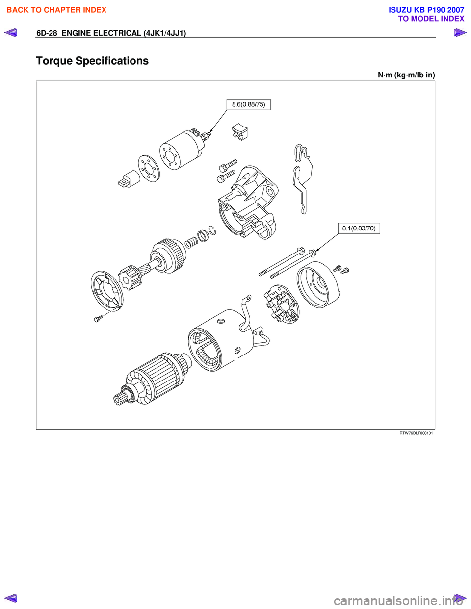
Torque Specifications
N⋅
⋅⋅
⋅
m (kg ⋅
⋅⋅
⋅
m/lb in)
RTW 76DLF000101
BACK TO CHAPTER INDEX
TO MODEL INDEX
ISUZU KB P190 2007