Page 1513 of 6020

ENGINE MECHANICAL (4JK1/4JJ1) 6A-153
Installation
1. Install the crank case.
• Apply the liquid gasket (ThreeBond TB-1207C
or equivalent) and mount within 5 minutes.
Tightening torque: 25 N ⋅
⋅⋅
⋅
m (2.5 kg ⋅
⋅⋅
⋅
m / 18 lb ft)
RTW 56ASH015301
Legend
1. 2.0 - 3.0 mm (0.079 - 0.118 in)
2. 4.0 - 5.0 mm (0.157 - 0.197 in)
2. Install the oil pan.
• Apply the liquid gasket (ThreeBond TB-1207B
or equivalent)and mount within 5 minutes.
Tightening torque: 22 N ⋅
⋅⋅
⋅
m (2.2 kg ⋅
⋅⋅
⋅
m / 16 lb ft)
RTW 56ASH015201
Legend
1. 2.0 mm (0.079 in)
2. 3.0 mm (0.118 in)
3. Install the retainer.
• Apply the liquid gasket (ThreeBond TB-1207C
or equivalent) and mount within 5 minutes.
Tightening torque: 25 N ⋅
⋅⋅
⋅
m (2.5 kg ⋅
⋅⋅
⋅
m / 18 lb ft)
RTW 56ASH017701
Legend
1. 2 - 2.5 mm (0.079 - 0.098 in)
2. 2 - 2.5 mm (0.079 - 0.098 in)
RTW 76ASH002001
Legend
1. Retainer
2. Bolt
4. Install the timing gear case.
Refer to “Gear Case Assembly”.
5. Install the cylinder head.
Refer to “Cylinder Head”.
BACK TO CHAPTER INDEX
TO MODEL INDEX
ISUZU KB P190 2007
Page 1514 of 6020
6A-154 ENGINE MECHANICAL (4JK1/4JJ1)
6. Install the rear plate.
• Tighten the bolts to the specified torque.
Tightening torque: 82 N ⋅
⋅⋅
⋅
m (8.4 kg ⋅
⋅⋅
⋅
m / 61 lb ft)
7. Install the flywheel.
Refer to “Flywheel”.
8. Connect the earth terminal of crank case side.
Note:
Do not allow the caulked portion of the terminal to
interfere with nearby parts.
9. Install the oil level gage guide tube. • Apply the engine oil to the O-ring.
• Tighten the bolts to the specified torque.
Tightening torque: 25 N ⋅
⋅⋅
⋅
m (2.5 kg ⋅
⋅⋅
⋅
m / 18 lb ft)
10. Install the engine assembly.
Refer to “Engine Assembly”.
BACK TO CHAPTER INDEX
TO MODEL INDEX
ISUZU KB P190 2007
Page 1515 of 6020
ENGINE MECHANICAL (4JK1/4JJ1) 6A-155
Torque Specifications
RTW 56AMF001901
BACK TO CHAPTER INDEX
TO MODEL INDEX
ISUZU KB P190 2007
Page 1519 of 6020
ENGINE MECHANICAL (4JK1/4JJ1) 6A-159
RTW 56ASH025501
• Measure the Depth size of the gear case
housing surface and the oil pump housing gea
r
case side.
Depth size the gear case housing surface and the oil
pump housing gear case side
mm (in)
Standard 14.500 - 14.527 (0.5709 - 0.5719)
RTW 56ASH014801
Clearance between the gear side surface and the
gear side surface of the oil pump housing mm (in)
Standard 0.063 - 0.027 (0.0025 - 0.0011)
Limit 0.20 (0.0079)
Installation
1. Install the oil pump.
•
Apply engine oil to the oil pump attachment
gearbox.
• Tighten the bolts to the specified torque.
Tightening torque: 25 N ⋅
⋅⋅
⋅
m (2.5 kg ⋅
⋅⋅
⋅
m / 18 lb ft)
• Installed pump gear should be smooth to
rotate.
2. Install the gear case cover. • Apply the liquid gasket (Threebond TB-1207B
or equivalent) mount within 5 minutes.
RTW 56ASH020101
Legend
1. Apply the liquid gasket in area
BACK TO CHAPTER INDEX
TO MODEL INDEX
ISUZU KB P190 2007
Page 1520 of 6020

6A-160 ENGINE MECHANICAL (4JK1/4JJ1)
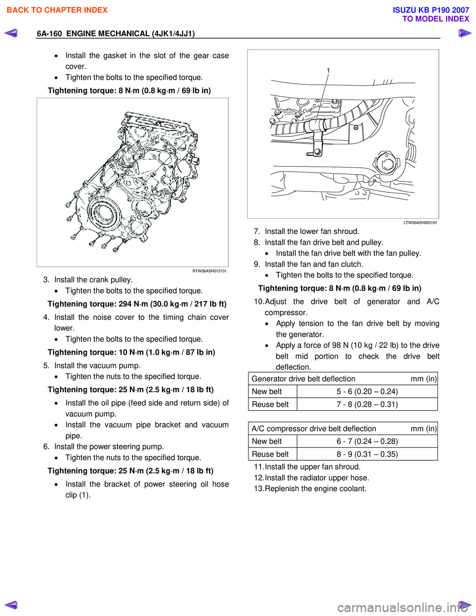
• Install the gasket in the slot of the gear case
cover.
• Tighten the bolts to the specified torque.
Tightening torque: 8 N ⋅
⋅⋅
⋅
m (0.8 kg ⋅
⋅⋅
⋅
m / 69 lb in)
RTW 56ASH012101
3. Install the crank pulley.
• Tighten the bolts to the specified torque.
Tightening torque: 294 N ⋅
⋅⋅
⋅
m (30.0 kg ⋅
⋅⋅
⋅
m / 217 lb ft)
4. Install the noise cover to the timing chain cove
r
lower.
• Tighten the bolts to the specified torque.
Tightening torque: 10 N ⋅
⋅⋅
⋅
m (1.0 kg ⋅
⋅⋅
⋅
m / 87 lb in)
5. Install the vacuum pump. • Tighten the nuts to the specified torque.
Tightening torque: 25 N ⋅
⋅⋅
⋅
m (2.5 kg ⋅
⋅⋅
⋅
m / 18 lb ft)
• Install the oil pipe (feed side and return side) o
f
vacuum pump.
• Install the vacuum pipe bracket and vacuum
pipe.
6. Install the power steering pump. • Tighten the nuts to the specified torque.
Tightening torque: 25 N ⋅
⋅⋅
⋅
m (2.5 kg ⋅
⋅⋅
⋅
m / 18 lb ft)
• Install the bracket of power steering oil hose
clip (1).
LTW 56ASH000101
7. Install the lower fan shroud.
8. Install the fan drive belt and pulley. • Install the fan drive belt with the fan pulley.
9. Install the fan and fan clutch. • Tighten the bolts to the specified torque.
Tightening torque: 8 N ⋅
⋅⋅
⋅
m (0.8 kg ⋅
⋅⋅
⋅
m / 69 lb in)
10.
Adjust the drive belt of generator and A/C
compressor.
• Apply tension to the fan drive belt by moving
the generator.
•
Apply a force of 98 N (10 kg / 22 lb) to the drive
belt mid portion to check the drive belt
deflection.
Generator drive belt deflection mm (in)
New belt 5 - 6 (0.20 – 0.24)
Reuse belt 7 - 8 (0.28 – 0.31)
A/C compressor drive belt deflection mm (in)
New belt 6 - 7 (0.24 – 0.28)
Reuse belt 8 - 9 (0.31 – 0.35)
11. Install the upper fan shroud.
12. Install the radiator upper hose.
13. Replenish the engine coolant.
BACK TO CHAPTER INDEX
TO MODEL INDEX
ISUZU KB P190 2007
Page 1522 of 6020

6A-162 ENGINE MECHANICAL (4JK1/4JJ1)
Removal
1. Remove the oil pressure SW .
2. Remove the nipple; oil gallery.
3. Remove the nipple; oil pressure warning SW and gasket.
Inspection
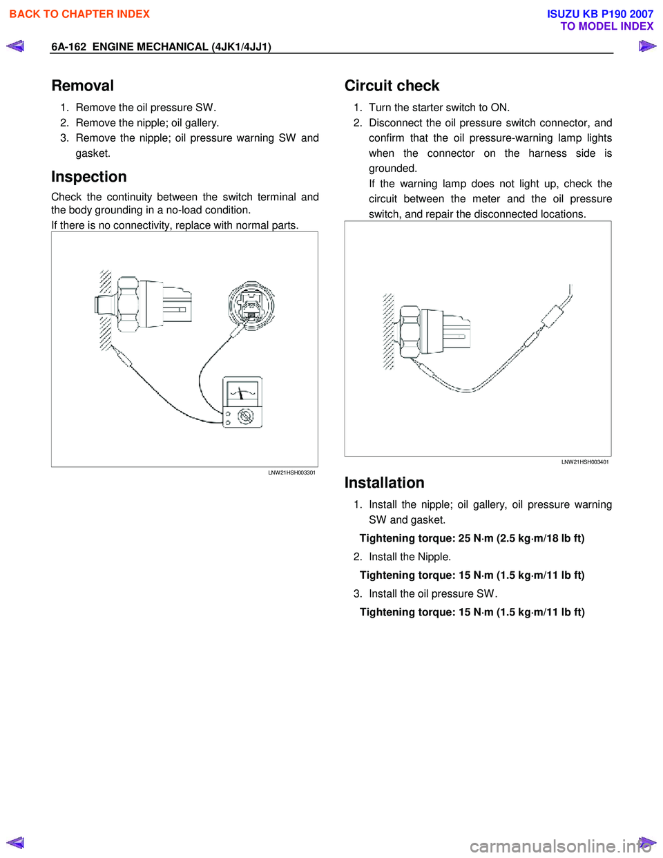
Check the continuity between the switch terminal and
the body grounding in a no-load condition.
If there is no connectivity, replace with normal parts.
LNW 21HSH003301
Circuit check
1. Turn the starter switch to ON.
2. Disconnect the oil pressure switch connector, and confirm that the oil pressure-warning lamp lights
when the connector on the harness side is
grounded.
If the warning lamp does not light up, check the circuit between the meter and the oil pressure
switch, and repair the disconnected locations.
LNW 21HSH003401
Installation
1. Install the nipple; oil gallery, oil pressure warning
SW and gasket.
Tightening torque: 25 N ⋅
⋅⋅
⋅
m (2.5 kg ⋅
⋅⋅
⋅
m/18 lb ft)
2. Install the Nipple. Tightening torque: 15 N ⋅
⋅⋅
⋅
m (1.5 kg ⋅
⋅⋅
⋅
m/11 lb ft)
3. Install the oil pressure SW . Tightening torque: 15 N ⋅
⋅⋅
⋅
m (1.5 kg ⋅
⋅⋅
⋅
m/11 lb ft)
BACK TO CHAPTER INDEX
TO MODEL INDEX
ISUZU KB P190 2007
Page 1532 of 6020

ENGINE COOLING (4JK1/4JJ1) 6B-9
Inspection and Repair
The water pump is not disassembled type.
Make necessary parts replacement if extreme wear o
r
damage is found during inspection. Should any of the
following problems occur, the entire water pump
assembly must be replaced.
• Cracks in the water pump body.
• Coolant leakage from the sealed unit.
• Excessive radial play or abnormal noise in the fan
center when rotated by hand.
• Excessive thrust play in the fan center (Standard
play: less than 0.2 mm (0.0078 in)).
• Cracks or corrosion in the impeller.
Installation
1. W ater Pump
RTW 56BSH000201
a. Install the water pump with a new gasket.
b. Tighten bolts and nuts to specified torque.
Water Pump Nut/Bolt Torque: 25 N·m (2.5 kg·m /18 lb ft)
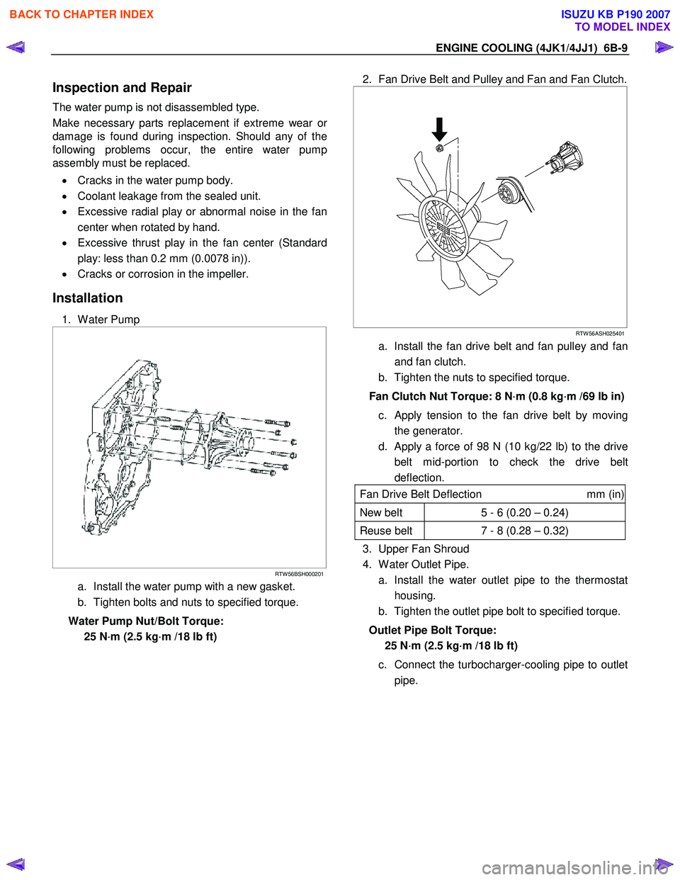
2. Fan Drive Belt and Pulley and Fan and Fan Clutch.
RTW 56ASH025401
a. Install the fan drive belt and fan pulley and fan
and fan clutch.
b. Tighten the nuts to specified torque.
Fan Clutch Nut Torque: 8 N·m (0.8 kg·m /69 lb in) c. Apply tension to the fan drive belt by moving the generator.
d. Apply a force of 98 N (10 kg/22 lb) to the drive belt mid-portion to check the drive belt
deflection.
Fan Drive Belt Deflection mm (in)
New belt 5 - 6 (0.20 – 0.24)
Reuse belt 7 - 8 (0.28 – 0.32)
3. Upper Fan Shroud
4. W ater Outlet Pipe.
a. Install the water outlet pipe to the thermostat housing.
b. Tighten the outlet pipe bolt to specified torque.
Outlet Pipe Bolt Torque: 25 N·m (2.5 kg·m /18 lb ft)
c. Connect the turbocharger-cooling pipe to outlet pipe.
BACK TO CHAPTER INDEX
TO MODEL INDEX
ISUZU KB P190 2007
Page 1535 of 6020
6B-12 ENGINE COOLING (4JK1/4JJ1)
MFW 41CSH001401
Legend
1. W ooden Piece
2. Agitating Rod
Installation
1. Thermostat
Install the thermostat.
Mount the jiggle valve with the valve facing engine front.
RTW 56BSH000101
Legend
1. Front
2. Thermostat
3. Jiggle Valve
2. W ater Outlet Pipe.
a. Install the water outlet pipe with new gasket to the thermostat housing.
b. Tighten the outlet pipe bolt to specified torque.
Outlet Pipe Bolt Torque: 25 N·m (2.5 kg·m /18 lb ft)
c. Connect the turbocharger-cooling pipe to outlet pipe.
d. Install the engine harness clip.
3. Radiator Upper Hose.
RTW 56FSH000101
a. Connect the radiator upper hose to the water
outlet pipe.
b. The knob of the clamp should be directed to the horizontal side.
c. Replenish the engine coolant.
4. Install the engine cover.
BACK TO CHAPTER INDEX
TO MODEL INDEX
ISUZU KB P190 2007