Page 1454 of 6020
6A-94 ENGINE MECHANICAL (4JK1/4JJ1)
24. Install the camshaft assembly.
• Align timing mark on intake camshaft and
exhaust camshaft to idle gear D.
RTW 56ASH007001
Legend
1. Exhaust Camshaft Gear
2. Intake Camshaft Gear
3. Idle Gear D
25. Install the camshaft bearing cap.
•
Apply engine oil to all of the cylinder head
journals.
RTW 56ASH013801
Tightening torque: 18 N ⋅
⋅⋅
⋅
m (1.8 kg ⋅
⋅⋅
⋅
m / 13 lb ft)
26. Align mark on camshaft to mark on camshaft
bearing cap.
• Align mark (1) on intake camshaft and exhaust
camshaft to mark of bearing cap.
RTW 56ASH006901
27. Remove the lock bolt from the camshaft gear.
28. Turn the crank pulley two rotation (720 °CA).
• Align mark on camshaft to mark on camshaft
bearing cap.
RTW 56ASH020701
Legend
1. Exhaust Camshaft Gear
2. Intake Camshaft Gear
3. Idle Gear D
BACK TO CHAPTER INDEX
TO MODEL INDEX
ISUZU KB P190 2007
Page 1455 of 6020

ENGINE MECHANICAL (4JK1/4JJ1) 6A-95
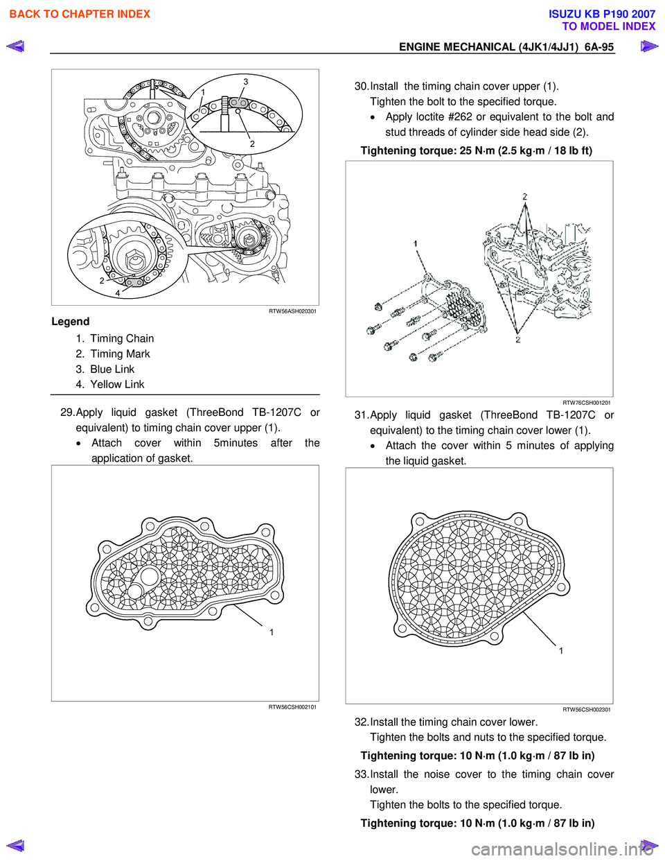
RTW 56ASH020301
Legend
1. Timing Chain
2. Timing Mark
3. Blue Link
4. Yellow Link
29. Apply liquid gasket (ThreeBond TB-1207C or
equivalent) to timing chain cover upper (1).
• Attach cover within 5minutes after the
application of gasket.
RTW 56CSH002101
30. Install the timing chain cover upper (1).
Tighten the bolt to the specified torque. •
Apply loctite #262 or equivalent to the bolt and
stud threads of cylinder side head side (2).
Tightening torque: 25 N ⋅
⋅⋅
⋅
m (2.5 kg ⋅
⋅⋅
⋅
m / 18 lb ft)
RTW 76CSH001201
31. Apply liquid gasket (ThreeBond TB-1207C or
equivalent) to the timing chain cover lower (1).
• Attach the cover within 5 minutes of applying
the liquid gasket.
RTW 56CSH002301
32. Install the timing chain cover lower.
Tighten the bolts and nuts to the specified torque.
Tightening torque: 10 N ⋅
⋅⋅
⋅
m (1.0 kg ⋅
⋅⋅
⋅
m / 87 lb in)
33. Install the noise cover to the timing chain cove
r
lower.
Tighten the bolts to the specified torque.
Tightening torque: 10 N ⋅
⋅⋅
⋅
m (1.0 kg ⋅
⋅⋅
⋅
m / 87 lb in)
BACK TO CHAPTER INDEX
TO MODEL INDEX
ISUZU KB P190 2007
Page 1456 of 6020
6A-96 ENGINE MECHANICAL (4JK1/4JJ1)
34. Inspection / adjustment of valve clearance.
• Refer to procedure for Service Precautions in
this manual.
35. Install the fuel injector. • Refer to procedure for Fuel System in this
manual.
36. Install the baffle cover. • Refer to procedure for Camshaft Assembly in
this manual.
37. Install the cam end gasket. • Apply the liquid gasket (ThreeBond TB-1207B
or equivalent).
RTW 56ASH020601
Legend
1. Cam End Gasket
2. 2.0 - 3.0 mm (0.078 - 0.118 in)
38. Install the cylinder head cover.
Refer to procedure for Cylinder Head Cover in this manual.
39. Install the glow plug .
Tighten the glow plug to the specified torque.
Tightening torque: 18 N ⋅
⋅⋅
⋅
m (1.8 kg ⋅
⋅⋅
⋅
m / 13 lb ft)
40. Install the glow plug connector.
Tighten the nut to the specified torque.
Tightening torque: 2 N ⋅
⋅⋅
⋅
m (0.2 kg ⋅
⋅⋅
⋅
m / 17 lb in)
RTW 56ASH010201
Legend
1. Glow Plug Connector
2. Nut
BACK TO CHAPTER INDEX
TO MODEL INDEX
ISUZU KB P190 2007
Page 1457 of 6020

ENGINE MECHANICAL (4JK1/4JJ1) 6A-97
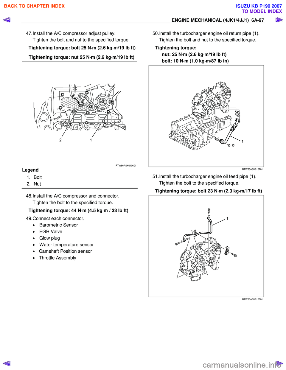
47. Install the A/C compressor adjust pulley.
Tighten the bolt and nut to the specified torque.
Tightening torque: bolt 25 N ⋅
⋅⋅
⋅
m (2.6 kg ⋅
⋅⋅
⋅
m/19 lb ft)
Tightening torque: nut 25 N ⋅
⋅⋅
⋅
m (2.6 kg ⋅
⋅⋅
⋅
m/19 lb ft)
RTW 56ASH010601
Legend
1. Bolt
2. Nut
48. Install the A/C compressor and connector.
Tighten the bolt to the specified torque.
Tightening torque: 44 N ⋅
⋅⋅
⋅
m (4.5 kg ⋅
⋅⋅
⋅
m / 33 lb ft)
49. Connect each connector. • Barometric Sensor
• EGR Valve
• Glow plug
• W ater temperature sensor
• Camshaft Position sensor
• Throttle Assembly
50. Install the turbocharger engine oil return pipe (1).
Tighten the bolt and nut to the specified torque.
Tightening torque: nut: 25 N ⋅
⋅⋅
⋅
m (2.6 kg ⋅
⋅⋅
⋅
m/19 lb ft)
bolt: 10 N ⋅
⋅⋅
⋅
m (1.0 kg ⋅
⋅⋅
⋅
m/87 lb in)
RTW 56ASH010701
51. Install the turbocharger engine oil feed pipe (1).
Tighten the bolt to the specified torque.
Tightening torque: bolt 23 N ⋅
⋅⋅
⋅
m (2.3 kg ⋅
⋅⋅
⋅
m/17 lb ft)
RTW 56ASH010801
BACK TO CHAPTER INDEX
TO MODEL INDEX
ISUZU KB P190 2007
Page 1460 of 6020
6A-100 ENGINE MECHANICAL (4JK1/4JJ1)
Torque Specifications
RTW 76AMF000201
Special Tools
ILLUSTRATION PART NO.
PART NAME
ILLUSTRATION PART NO.
PART NAME
5-8840-2820-0
Injection pipe oil seal installer
5-8840-0266-0
Angle gauge
5-8840-2816-0
Valve guide remover and installer
BACK TO CHAPTER INDEX
TO MODEL INDEX
ISUZU KB P190 2007
Page 1467 of 6020

ENGINE MECHANICAL (4JK1/4JJ1) 6A-107
LNW 21BSH010401
12. Measure the bearing oil clearance.
• Install the bearing to the connecting rod big
end.
• Tighten the bearing cap to the two step o
f
angular tightening method.
• Use an inside dial indicator to measure the
connecting rod bearing inside diameter.
Connecting rod bearing cap bolt torque:
N ⋅m (kg ⋅m / lb ft)
1st step 29.4 (3.0 / 22)
2nd step 45 deg
If the clearance between the measured bearing
inside diameter and the crankpin exceeds the
specified limit, the bearing and/or the crankshaft
must be replaced.
Crankpin and bearing clearance mm (in)
Standard 0.029 - 0.083 (0.0011 - 0.0033)
Limit 0.10 (0.0039)
Reassembly
1. Install the piston.
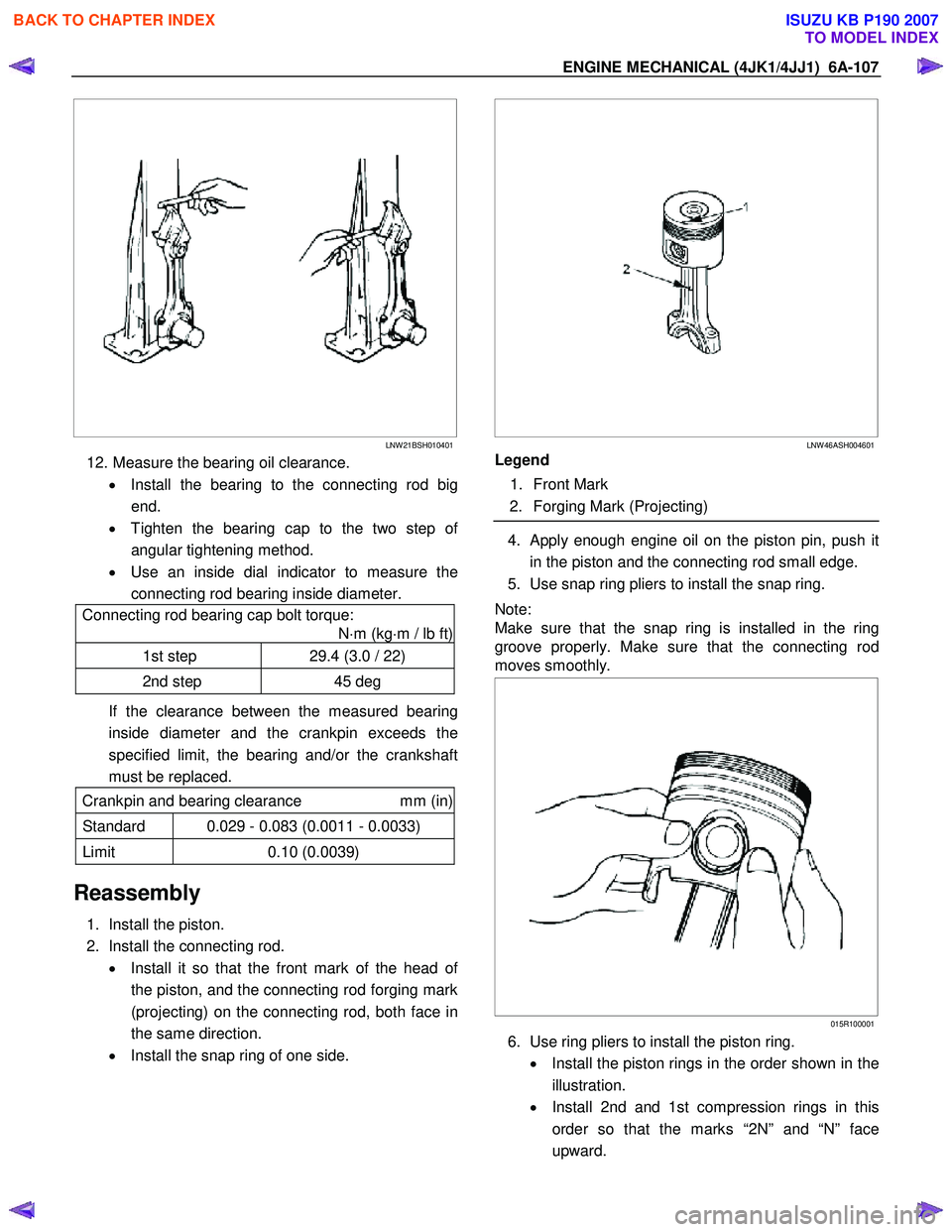
2. Install the connecting rod. • Install it so that the front mark of the head o
f
the piston, and the connecting rod forging mark
(projecting) on the connecting rod, both face in
the same direction.
• Install the snap ring of one side.
LNW 46ASH004601
Legend
1. Front Mark
2. Forging Mark (Projecting)
4. Apply enough engine oil on the piston pin, push it
in the piston and the connecting rod small edge.
5. Use snap ring pliers to install the snap ring.
Note:
Make sure that the snap ring is installed in the ring
groove properly. Make sure that the connecting rod
moves smoothly.
015R100001
6. Use ring pliers to install the piston ring.
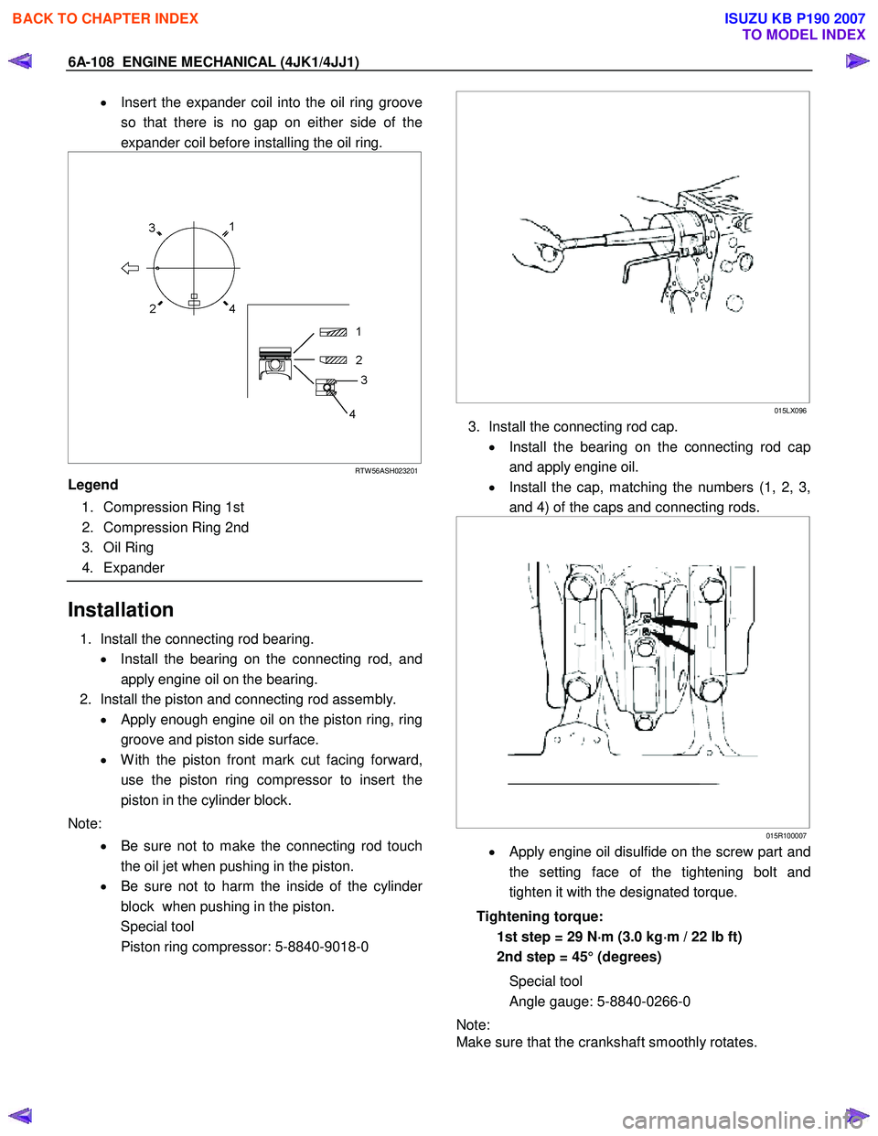
• Install the piston rings in the order shown in the
illustration.
• Install 2nd and 1st compression rings in this
order so that the marks “2N” and “N” face
upward.
BACK TO CHAPTER INDEX
TO MODEL INDEX
ISUZU KB P190 2007
Page 1468 of 6020

6A-108 ENGINE MECHANICAL (4JK1/4JJ1)
• Insert the expander coil into the oil ring groove
so that there is no gap on either side of the
expander coil before installing the oil ring.
RTW 56ASH023201
Legend
1. Compression Ring 1st
2. Compression Ring 2nd
3. Oil Ring
4. Expander
Installation
1. Install the connecting rod bearing.
• Install the bearing on the connecting rod, and
apply engine oil on the bearing.
2. Install the piston and connecting rod assembly. • Apply enough engine oil on the piston ring, ring
groove and piston side surface.
• W ith the piston front mark cut facing forward,
use the piston ring compressor to insert the
piston in the cylinder block.
Note: • Be sure not to make the connecting rod touch
the oil jet when pushing in the piston.
• Be sure not to harm the inside of the cylinde
r
block when pushing in the piston.
Special tool
Piston ring compressor: 5-8840-9018-0
015LX096
3. Install the connecting rod cap.
• Install the bearing on the connecting rod cap
and apply engine oil.
• Install the cap, matching the numbers (1, 2, 3,
and 4) of the caps and connecting rods.
015R100007
• Apply engine oil disulfide on the screw part and
the setting face of the tightening bolt and
tighten it with the designated torque.
Tightening torque: 1st step = 29 N ⋅
⋅⋅
⋅
m (3.0 kg ⋅
⋅⋅
⋅
m / 22 lb ft)
2nd step = 45° (degrees)
Special tool
Angle gauge: 5-8840-0266-0
Note:
Make sure that the crankshaft smoothly rotates.
BACK TO CHAPTER INDEX
TO MODEL INDEX
ISUZU KB P190 2007
Page 1470 of 6020
6A-110 ENGINE MECHANICAL (4JK1/4JJ1)
Torque Specifications
RTW 56AMF001801
Special Tools
ILLUSTRATION PART NO.
PART NAME
5-8840-9018-0
Piston ring compressor
5-8840-0266-0
Angle gauge
BACK TO CHAPTER INDEX
TO MODEL INDEX
ISUZU KB P190 2007