Page 1540 of 6020
ENGINE COOLING (4JK1/4JJ1) 6B-17
Fan Clutch with Cooling Fan
Inspection and Repair
Make necessary correction or parts replacement if
wear, damage or any other abnormal conditions are
found through inspection.
Visually inspect for damage, leak (silicon grease) o
r
other abnormal conditions.
1. Inspection (on-vehicle) a) Turn the fan clutch by hand when in a lo
w
temperature condition before starting the
engine, and confirm that it can be turned
readily.
b) Start the engine to warm it up until the temperature at the fan clutch portion gets to
around 85°C (185°F). Then stop the engine and
confirm that the fan clutch can be turned with
considerable effort (clutch torque) when turned
by hand.
If the fan clutch rotates more readily, however, this indicates that the silicone grease is leaking
internally.
Replace the fan clutch with a new one.
RTW 56ASH025401
2. Inspection (in unit)
W arm up the bimetal of the fan clutch by using the heat gun until the temperature gets to about 85°C
when measured with the thermistor. Then confirm
that the fan clutch can be turned with considerable
effort (clutch torque).
If the fan clutch rotates more readily at this time, this indicates that the silicone grease is leaking
internally.
Replace the fan clutch with a new one.
033RY00011
BACK TO CHAPTER INDEX
TO MODEL INDEX
ISUZU KB P190 2007
Page 1542 of 6020
FUEL SYSTEM (4JK1/4JJ1) 6C-1
SECTION 6C
FUEL SYSTEM
TABLE OF CONTENTS
Fuel System ....................................................... 6C-2 Service Precautions ........................................ 6C-2
Trouble Shooting ............................................. 6C-8
Fuel System Check ......................................... 6C-10
Fuel Filter Assembly ........................................... 6C-12 Components .................................................... 6C-12
Removal .......................................................... 6C-12
Installation ....................................................... 6C-12
Fuel Filter Cartridge............................................ 6C-13 Removal .......................................................... 6C-13
Installation ....................................................... 6C-13
Fuel Injector........................................................ 6C-14 Components .................................................... 6C-14
Removal .......................................................... 6C-15
Installation ....................................................... 6C-15
Torque Specifications...................................... 6C-18
Fuel Rail Pressure Sensor ................................. 6C-19 Removal .......................................................... 6C-19
Installation ....................................................... 6C-19
Fuel Pressure Limiter ......................................... 6C-20 Removal .......................................................... 6C-20
Installation ....................................................... 6C-20
Fuel Rail Assembly............................................. 6C-21 Components .................................................... 6C-21
Removal .......................................................... 6C-22
Disassembly .................................................... 6C-24
Reassembly..................................................... 6C-24
Installation ....................................................... 6C-24
Torque Specifications...................................... 6C-26
Fuel Supply Pump .............................................. 6C-27 Components .................................................... 6C-27
Removal .......................................................... 6C-28
Installation ....................................................... 6C-33
Torque Specifications...................................... 6C-38
Fuel Sedimenter Switch ..................................... 6C-39 Inspection ........................................................ 6C-39
Fuel Tank and Fuel Cooler ................................. 6C-40 Fuel Tank and Associated Parts ..................... 6C-40
Removal .......................................................... 6C-41
Installation ....................................................... 6C-41
Fuel Gauge Unit ................................................. 6C-42 Fuel Gauge Unit and Associated Parts ........... 6C-42
Removal .......................................................... 6C-43
Installation ....................................................... 6C-43
Special Tool .................................................... 6C-43
Fuel Tube/Quick-Connector Fittings .................. 6C-44 Precautions ..................................................... 6C-44
Cautions During W ork ..................................... 6C-44
Removal .......................................................... 6C-44
Reuse of Quick-Connector.............................. 6C-45
Assembling Advice .......................................... 6C-45
Filler Neck .......................................................... 6C-46 Removal .......................................................... 6C-46
Installation ....................................................... 6C-46
Fuel Filler Cap .................................................... 6C-47 General Description ........................................ 6C-47
Inspection ........................................................ 6C-47
BACK TO CHAPTER INDEX
TO MODEL INDEX
ISUZU KB P190 2007
Page 1547 of 6020
6C-6 FUEL SYSTEM (4JK1/4JJ1)
Fuel injector
RTW 76CMH000201
Legend
1. Terminal
2. Fuel Injector ID Code
3. Two Dimensional Barcode
4. Parts Number
5. Port for Mounting the Injection Pipe
6. O-ring
Fuel filter
RTW 76CSH001001
Legend
1. Element
2. Air Bleeding Plug
3. Switch; Clogging Monitoring
4. Sensor; W ater
5. Drain Plug
Functional check
Air bleeding
1. Ignition switch is turned to the ON position for 15 seconds.
2. Ignition switch is turned to the OFF position.
3. The above operation is repeated 5 times.
Note: If the air bleeding work is insufficient then it could
lead to faults in the engine. Therefore, the procedures
after starting the engine should always be implemented.
Water drain
A warning lamp will light up if water above the specified
volume collects in the sedimenter. In such cases, drain
out the water by performing the following operations:
1. Draining with fuel filter drain plug. a. Set a container at the tip of the plastic hose.
b. Loosen the air bleeding plug and the drain plug.
c. Discharge the water.
d. Tighten the drain plug after discharging the water.
e. Tighten the air bleeding plug to the specified torque.
Tightening torque: 3 N ⋅m(0.3 kg ⋅m/26 lb in)
f. Ignition switch is turned ON for 15 seconds check for fuel leakage.
BACK TO CHAPTER INDEX
TO MODEL INDEX
ISUZU KB P190 2007
Page 1554 of 6020
FUEL SYSTEM (4JK1/4JJ1) 6C-13
Fuel Filter Element
Removal
1. Detach the drain hose on the lower part of the fuel
filter or the drain plug, loosen the air bleed plug,
and drain the fuel from the fuel filter.
2. Detach the water-in-fuel switch harness.
3. Turn the element case counterclockwise to detach, and remove the filter element.
4. Replace the O-ring and confirm the snap-fit position, and fit a new filter element inside the
element case.
NOTE
It is strongly advisable to use the ISUZU/GM genuine
fuel filter for replacement.
RTW 76CSH000901
Legend
1. Element
2. O-ring
3. Sedimenter Sensor
Installation
1. Apply a light coat of new diesel oil to the O-ring
and gasket.
2. Turn the element case clockwise until it is completely seated against the upper cover. Then
check that the drain hose is in its correct position,
and then use a filter wrench and tighten to the
specified torque.
Tightening torque: 25 N ⋅
⋅⋅
⋅
m (2.5 kg ⋅
⋅⋅
⋅
m / 18 lb ft)
3. Use a clip to fix the drain hose at the base of the fuel filter, and fit the water-in-fuel switch harness.
BACK TO CHAPTER INDEX
TO MODEL INDEX
ISUZU KB P190 2007
Page 1557 of 6020
6C-16 FUEL SYSTEM (4JK1/4JJ1)
3. Apply Engine oil to the threads and seating
surfaces of the clamp bolts.
4. Install the fuel injector clamps to the cylinder head.
5. Temporarily tighten the clamp bolts.
6.
Apply a thin coat of engine oil to the outer surface
of the fuel injector side sleeve nuts.
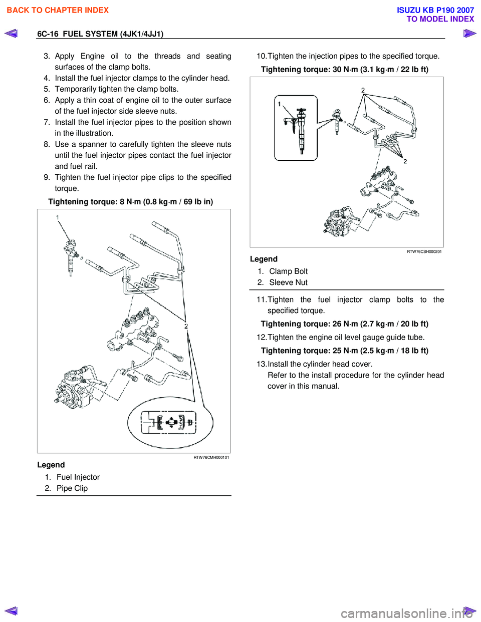
7. Install the fuel injector pipes to the position shown in the illustration.
8. Use a spanner to carefully tighten the sleeve nuts until the fuel injector pipes contact the fuel injecto
r
and fuel rail.
9. Tighten the fuel injector pipe clips to the specified torque.
Tightening torque: 8 N ⋅
⋅⋅
⋅
m (0.8 kg ⋅
⋅⋅
⋅
m / 69 lb in)
RTW 76CMH000101
Legend
1. Fuel Injector
2. Pipe Clip
10. Tighten the injection pipes to the specified torque.
Tightening torque: 30 N ⋅
⋅⋅
⋅
m (3.1 kg ⋅
⋅⋅
⋅
m / 22 lb ft)
RTW 76CSH000201
Legend
1. Clamp Bolt
2. Sleeve Nut
11. Tighten the fuel injector clamp bolts to the
specified torque.
Tightening torque: 26 N ⋅
⋅⋅
⋅
m (2.7 kg ⋅
⋅⋅
⋅
m / 20 lb ft)
12. Tighten the engine oil level gauge guide tube. Tightening torque: 25 N ⋅
⋅⋅
⋅
m (2.5 kg ⋅
⋅⋅
⋅
m / 18 lb ft)
13. Install the cylinder head cover.
Refer to the install procedure for the cylinder head cover in this manual.
BACK TO CHAPTER INDEX
TO MODEL INDEX
ISUZU KB P190 2007
Page 1559 of 6020
6C-18 FUEL SYSTEM (4JK1/4JJ1)
Torque Specifications
RTW 76CLF000201
BACK TO CHAPTER INDEX
TO MODEL INDEX
ISUZU KB P190 2007
Page 1560 of 6020
FUEL SYSTEM (4JK1/4JJ1) 6C-19
Fuel Rail Pressure Sensor
Removal
1. Disconnect the fuel pressure sensor harness
connector (1).
LNW 76CSH001601
2. Remove the fuel pressure sensor (2).
Note: Cover the areas exposed during parts removal to
prevent the entry of foreign material into the fuel
system.
RTW 76CSH000101
Legend
1. Fuel Rail
2. Fuel Rail Pressure Sensor
3. Fuel Pressure Limiter
Installation
1. Install the fuel pressure sensor.
Tightening torque: 98 N·m (10.0 kg·m/72 lb ft)
2. Connect the fuel pressure sensor connector.
BACK TO CHAPTER INDEX
TO MODEL INDEX
ISUZU KB P190 2007
Page 1561 of 6020
6C-20 FUEL SYSTEM (4JK1/4JJ1)
Fuel Pressure Limiter
Removal
1. Remove the leak off pipe and hose (1).
Note: Cover the areas exposed during parts removal to
prevent the entry of foreign material into the fuel
system.
RTW 76CSH000301
2. Remove the fuel pressure limiter.
Note: Cover the areas exposed during part removal to
prevent the entry of foreign material into the fuel
system.
RTW 76CSH000101
Legend
1. Fuel Rail
2. Fuel Rail Pressure Sensor
3. Fuel Pressure Limiter
Installation
1. Install the fuel pressure limiter.
Tightening torque: 172 N·m (17.5 kg·m/127 lb ft)
2. Install the fuel leak off pipe and hose using the mounting eyebolt using the specified torque.
Tightening torque: 10 N ⋅
⋅⋅
⋅
m (1.0 kg ⋅
⋅⋅
⋅
m/87 lb in)
BACK TO CHAPTER INDEX
TO MODEL INDEX
ISUZU KB P190 2007