Page 2042 of 6020
6A-28 ENGINE MECHANICAL (C24SE)
2. Install cable to temperature sensor.
3. Install upper bolts of rear toothed belt rear cover.
4. Install camshaft timing gear then check timing according to the corresponding operation.
5. Install camshaft housing cover.
6. Install toothed belt and front cover.
7. Fill up and bleed cooling system according to the corresponding operation.
Tighten (Torque)
Thermostat housing to cylinder head - 15 N ⋅m/1.5 kgf ⋅m.
Seal Ring - Front Camshaft Housing, Replace
Removal
Mark running direction of toothed belt.
Remove toothed belt-see operation “Toothed Belt, Replace”.
Camshaft housing cover, camshaft pulley-counterhold on hex
of camshaft.
Removal
Screw self-tapping screw into seal ring.
Edge out seal ring.
Installation
Lightly coat sealing lip of seal ring with protective grease.
Install seal ring with 5-8840-0451-0 into camshaft housing-use
screw and washer of camshaft pulley.
BACK TO CHAPTER INDEX
TO MODEL INDEX
ISUZU KB P190 2007
Page 2043 of 6020
ENGINE MECHANICAL (C24SE) 6A-29
Installation
Camshaft pulley-counterhold at hex head of camshaft,
camshaft housing cover.
Toothed belt-see operation “Toothed Belt, Replace”.
Note operating erection of toothed belt.
Tighten (Torque)
Camshaft pulley to cammshaft-45 N ⋅m (3.7 kgf ⋅m)
Tighten (Torque)
Camshaft housing cover to cover to housing-8 N ⋅m (0.8 kgf ⋅m)
BACK TO CHAPTER INDEX
TO MODEL INDEX
ISUZU KB P190 2007
Page 2045 of 6020

ENGINE MECHANICAL (C24SE) 6A-31
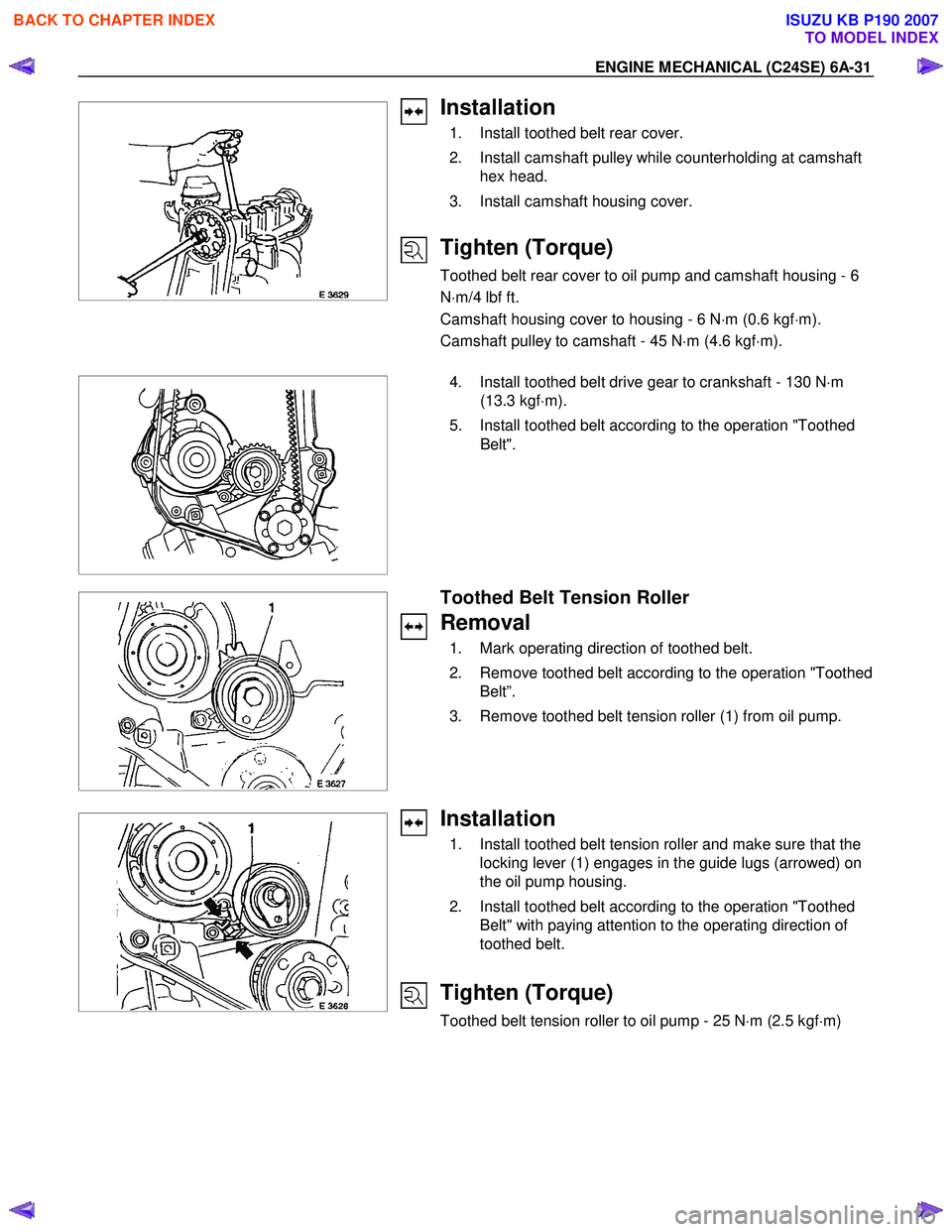
Installation
1. Install toothed belt rear cover.
2. Install camshaft pulley while counterholding at camshaft hex head.
3. Install camshaft housing cover.
Tighten (Torque)
Toothed belt rear cover to oil pump and camshaft housing - 6
N ⋅m/4 lbf ft.
Camshaft housing cover to housing - 6 N ⋅m (0.6 kgf ⋅m).
Camshaft pulley to camshaft - 45 N ⋅m (4.6 kgf ⋅m).
4. Install toothed belt drive gear to crankshaft - 130 N
⋅m
(13.3 kgf ⋅m).
5. Install toothed belt according to the operation "Toothed Belt".
Toothed Belt Tension Roller
Removal
1. Mark operating direction of toothed belt.
2. Remove toothed belt according to the operation "Toothed Belt”.
3. Remove toothed belt tension roller (1) from oil pump.
Installation
1. Install toothed belt tension roller and make sure that the locking lever (1) engages in the guide lugs (arrowed) on
the oil pump housing.
2. Install toothed belt according to the operation "Toothed Belt" with paying attention to the operating direction of
toothed belt.
Tighten (Torque)
Toothed belt tension roller to oil pump - 25 N ⋅m (2.5 kgf ⋅m)
BACK TO CHAPTER INDEX
TO MODEL INDEX
ISUZU KB P190 2007
Page 2048 of 6020
6A-34 ENGINE MECHANICAL (C24SE)
OPERATIONS ON CYLINDER HEAD AND CAMSHAFT
HOUSING
Camshaft
Removal
1. Remove cylinder head according to the corresponding
operation.
2. Remove camshaft housing from cylinder head and lay housing on base provided
3. Remove rear sealing gasket and plate camshaft housing with taking care not to damage housing.
4. Remove thrust plate.
5. Remove camshaft.
6. Remove front sealing gasket and plate from camshaft housing with taking care not to damage housing.
Inspection
All parts.
Installation
1. Install camshaft.
2. Coat sliding surfaces with molybdenum disulphate paste.
Tighten (Torque)
Thrust plate for camshaft housing - 8 N ⋅m (0.8 kgf ⋅m)
BACK TO CHAPTER INDEX
TO MODEL INDEX
ISUZU KB P190 2007
Page 2050 of 6020

6A-36 ENGINE MECHANICAL (C24SE)
Clean
All sealing surfaces, drill holes in cylinder head bolts.
Check cylinder block and cylinder head for plane surface
according to the corresponding operations.
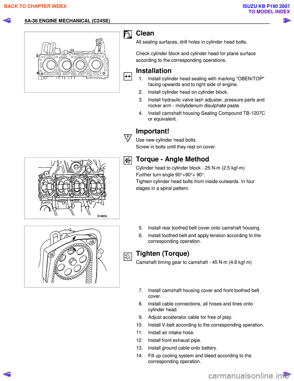
Installation
1. Install cylinder head sealing with marking "OBEN/TOP"
facing upwards and to right side of engine.
2. Install cylinder head on cylinder block.
3. Install hydraulic valve lash adjuster, pressure parts and rocker arm - molybdenum disulphate paste.
4. Install camshaft housing-Sealing Compound TB-1207C or equivalent.
Important!
Use new cylinder head bolts.
Screw in bolts until they rest on cover.
Torque - Angle Method
Cylinder head to cylinder block - 25 N ⋅m (2.5 kgf ⋅m)
Further turn angle 90 °+90 °+ 90 °.
Tighten cylinder head bolts from inside outwards. In four
stages in a spiral pattern.
5. Install rear toothed belt cover onto camshaft housing.
6. Install toothed belt and apply tension according to the corresponding operation.
Tighten (Torque)
Camshaft timing gear to camshaft - 45 N ⋅m (4.6 kgf ⋅m)
7. Install camshaft housing cover and front toothed belt
cover.
8. Install cable connections, all hoses and lines onto cylinder head.
9. Adjust accelerator cable for free of play.
10. Install V-belt according to the corresponding operation.
11. Install air intake hose.
12. Install front exhaust pipe.
13. Install ground cable onto battery.
14. Fill up cooling system and bleed according to the corresponding operation.
BACK TO CHAPTER INDEX
TO MODEL INDEX
ISUZU KB P190 2007
Page 2052 of 6020
6A-38 ENGINE MECHANICAL (C24SE)
Inspection
All parts, if necessary replace.
W hen replacing camshaft, always replace all cam followers.
Installation
Insert hydraulic valve lifter (1) in camshaft housing.
Coat sliding surfaces of rocker arm with Mcs, Paste and insert
in camshaft housing.
Adjust
Adjustment of the hydraulic valve liters is not required.
Pretension is provided by the design.
Installation
1. Remove 5-8840-0457-0 and install the camshaft housing cover.
2. Insert the spark plug connectors.
Tighten (Torque)
Guide plate to camshaft housing.
Insert camshaft with MoS
2 paste.
Installation
1. Install the front seal ring in camshaft housing with 5-8840-0451-0.
2. Install the camshaft housing rear cover.
3. Install the cylinder head.
BACK TO CHAPTER INDEX
TO MODEL INDEX
ISUZU KB P190 2007
Page 2055 of 6020
ENGINE MECHANICAL (C24SE) 6A-41
Installation
1. Install the cylinder head gasket.
Mark "OBEN/TOP" on top and turn it towards timing side of engine.
2. Place cylinder head on cylinder block.
1
2
3
Installation
1. Insert the hydraulic valve lifters (3), thrust pieces (2) and
cam followers (1) with MoS2 paste.
Note allocation.
2. Apply a bead of Sealing Compound TB1207C to sealing surface of cylinder head.
3. Install the camshaft housing on cylinder head.
Torque-Angle Method
Cylinder head and camshaft housing with new cylinder head
bolts to cylinder block.
Cylinder head bolts in sequence shown.
Installation
1. Install the rear toothed belt cover to camshaft housing.
2. Install the camshaft pulley to camshaft.
3. Install the camshaft housing cover to housing.
Installation
1. Install the toothed belt on camshaft pulley.
See operation "Timing Adjust".
2. Install the front toothed belt cover.
BACK TO CHAPTER INDEX
TO MODEL INDEX
ISUZU KB P190 2007
Page 2057 of 6020

ENGINE MECHANICAL (C24SE) 6A-43
Inspection
Sealing surfaces for plane surface, guides, sliding and bearing
points for wear-see operation “Cylinder Head. Overhaul”.
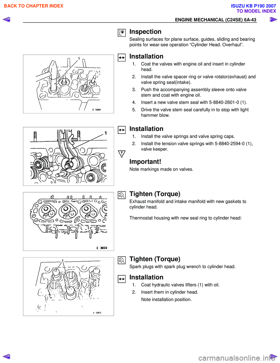
Installation
1. Coat the valves with engine oil and insert in cylinder head.
2. Install the valve spacer ring or valve rotator(exhaust) and valve spring seal(intake).
3. Push the accompanying assembly sleeve onto valve stem and coat with engine oil.
4. Insert a new valve stem seal with 5-8840-2601-0 (1).
5. Drive the valve stem seal carefully in to stop with light hammer blow.
Installation
1. Install the valve springs and valve spring caps.
2. Install the tension valve springs with 5-8840-2594-0 (1), valve keeper.
Important!
Note markings made on valves.
Tighten (Torque)
Exhaust manifold and intake manifold with new gaskets to
cylinder head.
Thermostat housing with new seal ring to cylinder head:
Tighten (Torque)
Spark plugs with spark plug wrench to cylinder head.
Installation
1. Coat hydraulic valves lifters (1) with oil.
2. Insert them in cylinder head.
Note installation position.
BACK TO CHAPTER INDEX
TO MODEL INDEX
ISUZU KB P190 2007