2007 ISUZU KB P190 light
[x] Cancel search: lightPage 3764 of 6020
Automatic Transmission – 4L60E – General Information Page 7C1–4
1.2 7C1 Automatic Transmission – 4L60E –
General Information
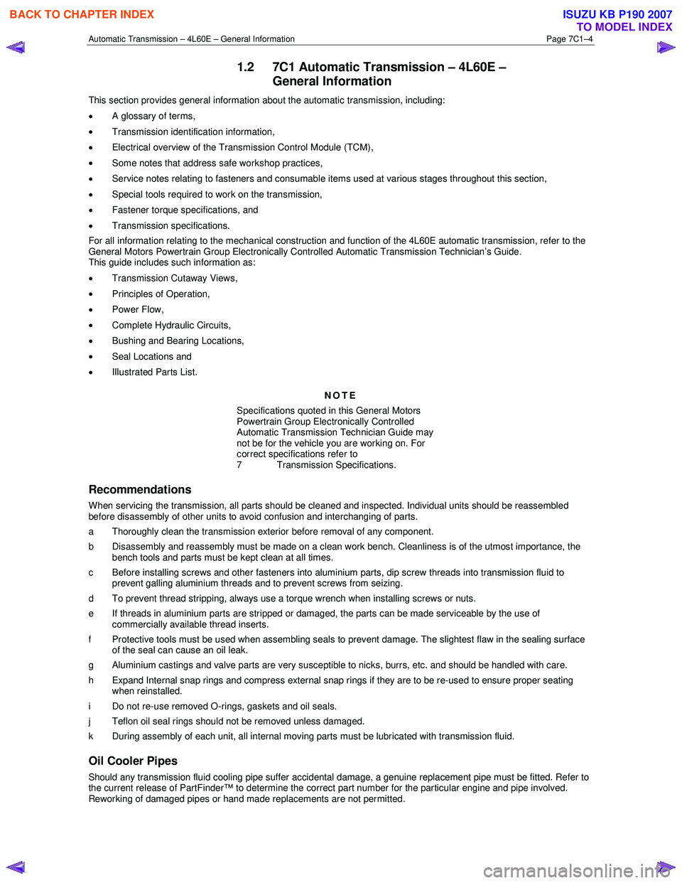
This section provides general information about the automatic transmission, including:
• A glossary of terms,
• Transmission identification information,
• Electrical overview of the Transmission Control Module (TCM),
• Some notes that address safe workshop practices,
• Service notes relating to fasteners and consumable items used at various stages throughout this section,
• Special tools required to work on the transmission,
• Fastener torque specifications, and
• Transmission specifications.
For all information relating to the mechanical construction and function of the 4L60E automatic transmission, refer to the
General Motors Powertrain Group Electronically Controlled Automatic Transmission Technician’s Guide.
This guide includes such information as:
• Transmission Cutaway Views,
• Principles of Operation,
• Power Flow,
• Complete Hydraulic Circuits,
• Bushing and Bearing Locations,
• Seal Locations and
• Illustrated Parts List.
NOTE
Specifications quoted in this General Motors
Powertrain Group Electronically Controlled
Automatic Transmission Technician Guide may
not be for the vehicle you are working on. For
correct specifications refer to
7 Transmission Specifications.
Recommendations
When servicing the transmission, all parts should be cleaned and inspected. Individual units should be reassembled
before disassembly of other units to avoid confusion and interchanging of parts.
a Thoroughly clean the transmission exterior before removal of any component.
b Disassembly and reassembly must be made on a clean work bench. Cleanliness is of the utmost importance, the bench tools and parts must be kept clean at all times.
c Before installing screws and other fasteners into aluminium parts, dip screw threads into transmission fluid to prevent galling aluminium threads and to prevent screws from seizing.
d To prevent thread stripping, always use a torque wrench when installing screws or nuts.
e If threads in aluminium parts are stripped or damaged, the parts can be made serviceable by the use of commercially available thread inserts.
f Protective tools must be used when assembling seals to prevent damage. The slightest flaw in the sealing surface of the seal can cause an oil leak.
g Aluminium castings and valve parts are very susceptible to nicks, burrs, etc. and should be handled with care.
h Expand Internal snap rings and compress external snap rings if they are to be re-used to ensure proper seating when reinstalled.
i Do not re-use removed O-rings, gaskets and oil seals.
j Teflon oil seal rings should not be removed unless damaged.
k During assembly of each unit, all internal moving parts must be lubricated with transmission fluid.
Oil Cooler Pipes
Should any transmission fluid cooling pipe suffer accidental damage, a genuine replacement pipe must be fitted. Refer to
the current release of PartFinder™ to determine the correct part number for the particular engine and pipe involved.
Reworking of damaged pipes or hand made replacements are not permitted.
BACK TO CHAPTER INDEX
TO MODEL INDEX
ISUZU KB P190 2007
Page 3771 of 6020
Automatic Transmission – 4L60E – General Information Page 7C1–11
4 Transmission Definitions and
Abbreviations
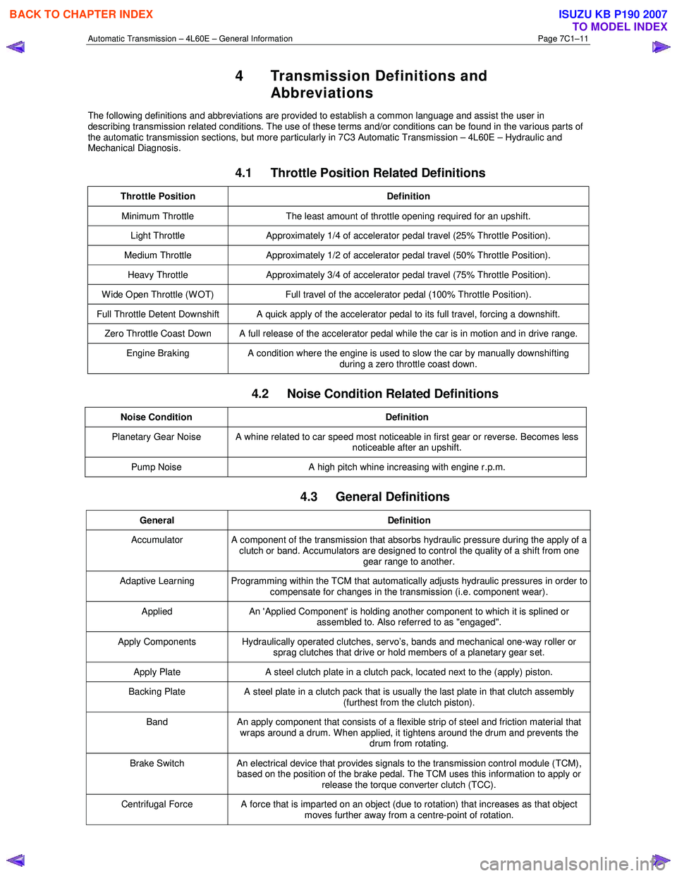
The following definitions and abbreviations are provided to establish a common language and assist the user in
describing transmission related conditions. The use of these terms and/or conditions can be found in the various parts of
the automatic transmission sections, but more particularly in 7C3 Automatic Transmission – 4L60E – Hydraulic and
Mechanical Diagnosis.
4.1 Throttle Position Related Definitions
Throttle Position Definition
Minimum Throttle The least amount of throttle opening required for an upshift.
Light Throttle Approximately 1/4 of accelerator pedal travel (25% Throttle Position).
Medium Throttle Approximately 1/2 of accelerator pedal travel (50% Throttle Position).
Heavy Throttle Approximately 3/4 of accelerator pedal travel (75% Throttle Position).
Wide Open Throttle (WOT) Full travel of the accelerator pedal (100% Throttle Position).
Full Throttle Detent Downshift A quick apply of the accelerator pedal to its full travel, forcing a downshift.
Zero Throttle Coast Down A full release of the accelerator pedal while the car is in motion and in drive range.
Engine Braking A condition where the engine is used to slow the car by manually downshifting
during a zero throttle coast down.
4.2 Noise Condition Related Definitions
Noise Condition Definition
Planetary Gear Noise A whine related to car speed most noticeable in first gear or reverse. Becomes less
noticeable after an upshift.
Pump Noise A high pitch whine increasing with engine r.p.m.
4.3 General Definitions
General Definition
Accumulator A component of the transmission that absorbs hydraulic pressure during the apply of a
clutch or band. Accumulators are designed to control the quality of a shift from one gear range to another.
Adaptive Learning Programming within the TCM that automatically adjusts hydraulic pressures in order to compensate for changes in the transmission (i.e. component wear).
Applied An 'Applied Component' is holding another component to which it is splined or
assembled to. Also referred to as "engaged".
Apply Components Hydraulically operated clutches, servo’s, bands and mechanical one-way roller or
sprag clutches that drive or hold members of a planetary gear set.
Apply Plate A steel clutch plate in a clutch pack, located next to the (apply) piston.
Backing Plate A steel plate in a clutch pack that is usually the last plate in that clutch assembly
(furthest from the clutch piston).
Band An apply component that consists of a flexible strip of steel and friction material that
wraps around a drum. When applied, it tightens around the drum and prevents the drum from rotating.
Brake Switch An electrical device that provides signals to the transmission control module (TCM),
based on the position of the brake pedal. The TCM uses this information to apply or
release the torque converter clutch (TCC).
Centrifugal Force A force that is imparted on an object (due to rotation) that increases as that object moves further away from a centre-point of rotation.
BACK TO CHAPTER INDEX
TO MODEL INDEX
ISUZU KB P190 2007
Page 3784 of 6020
Automatic Transmission – 4L60E – General Information Page 7C1–24
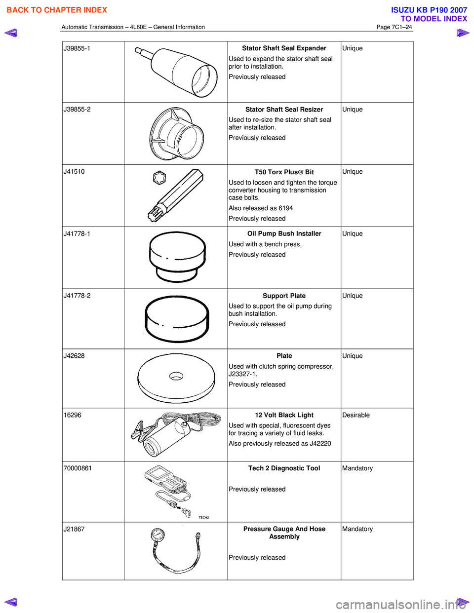
J39855-1
Stator Shaft Seal Expander
Used to expand the stator shaft seal
prior to installation.
Previously released Unique
J39855-2
Stator Shaft Seal Resizer
Used to re-size the stator shaft seal
after installation.
Previously released Unique
J41510
T50 Torx Plus
Bit
Used to loosen and tighten the torque
converter housing to transmission
case bolts.
Also released as 6194.
Previously released Unique
J41778-1
Oil Pump Bush Installer
Used with a bench press.
Previously released Unique
J41778-2
Support Plate
Used to support the oil pump during
bush installation.
Previously released Unique
J42628
Plate
Used with clutch spring compressor,
J23327-1.
Previously released Unique
16296 12 Volt Black Light
Used with special, fluorescent dyes
for tracing a variety of fluid leaks.
Also previously released as J42220 Desirable
70000861
Tech 2 Diagnostic Tool
Previously released Mandatory
J21867
Pressure Gauge And Hose
Assembly
Previously released Mandatory
BACK TO CHAPTER INDEX
TO MODEL INDEX
ISUZU KB P190 2007
Page 3785 of 6020
Automatic Transmission – 4L60E – General Information Page 7C1–25
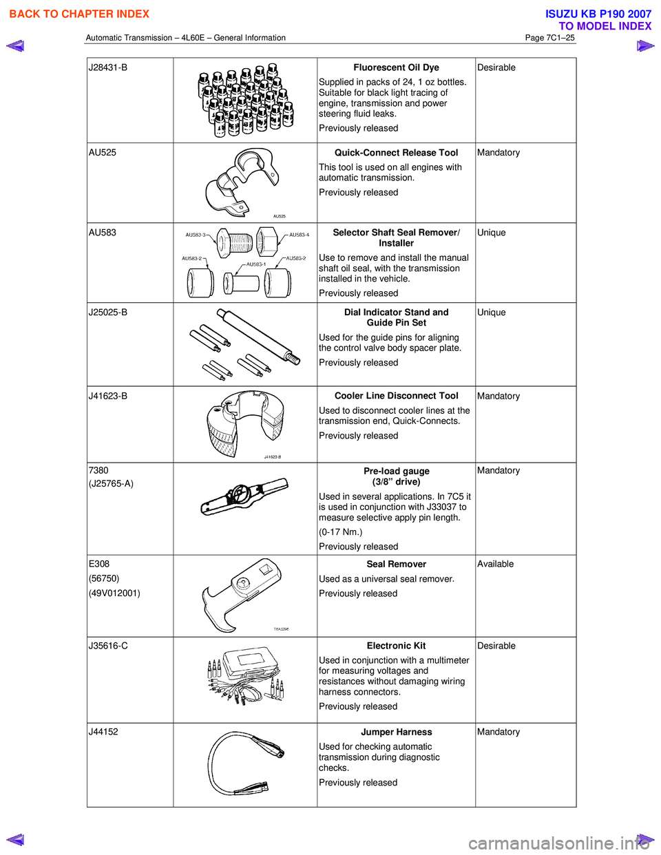
J28431-B
Fluorescent Oil Dye
Supplied in packs of 24, 1 oz bottles.
Suitable for black light tracing of
engine, transmission and power
steering fluid leaks.
Previously released Desirable
AU525
AU525 Quick-Connect Release Tool
This tool is used on all engines with
automatic transmission.
Previously released Mandatory
AU583 Selector Shaft Seal Remover/
Installer
Use to remove and install the manual
shaft oil seal, with the transmission
installed in the vehicle.
Previously released Unique
J25025-B
Dial Indicator Stand and
Guide Pin Set
Used for the guide pins for aligning
the control valve body spacer plate.
Previously released Unique
J41623-B
Cooler Line Disconnect Tool
Used to disconnect cooler lines at the
transmission end, Quick-Connects.
Previously released Mandatory
7380
(J25765-A)
Pre-load gauge
(3/8” drive)
Used in several applications. In 7C5 it
is used in conjunction with J33037 to
measure selective apply pin length.
(0-17 Nm.)
Previously released Mandatory
E308
(56750)
(49V012001)
Seal Remover
Used as a universal seal remover .
Previously released Available
J35616-C
Electronic Kit
Used in conjunction with a multimeter
for measuring voltages and
resistances without damaging wiring
harness connectors.
Previously released Desirable
J44152
Jumper Harness
Used for checking automatic
transmission during diagnostic
checks.
Previously released Mandatory
BACK TO CHAPTER INDEX
TO MODEL INDEX
ISUZU KB P190 2007
Page 3814 of 6020
Automatic Transmission – 4L60E – Electrical Diagnosis Page 7C2–28
7 Ensure that all wiring harness connectors are fitted correctly and secure.
8 W hen steam or pressure cleaning vehicle components, such as engines, transmissions, etc., do not direct the cleaning nozzle at any system electrical wiring harness connectors or components.
9 Do not clear any DTCs unless instructed.
10 The fault must be present when using the Diagnostic Trouble Code (DTC) Diagnostic Tables. Otherwise, misdiagnosis or replacement of good parts may occur.
11 Do not touch any electronic control module connector pins or soldered components on the circuit board. This is required to avoid the possibility of electrostatic discharge damage.
12 Use only the test equipment specified in the diagnostic tables, as other test equipment may give incorrect results or damage good components.
13 Electronic control modules are designed to withstand normal current draws associated with vehicle operation. However, the following fault conditions or incorrect test procedure may overload internal control module circuits and
irreparably damage the control module:
• A short to voltage fault condition in any of the control module low reference circuits may cause internal and/or
sensor damage. Therefore, any short to voltage fault condition in the control module low reference circuits
must be rectified before replacing a faulty component.
• A short to ground fault condition in any of the control module 5 volts reference circuits may cause internal
control module and/or sensor damage. Therefore, any short to ground fault condition in the control module 5
volt reference circuits must be rectified before replacing a faulty component.
• W hen using a test light to test an electrical circuit, do not use any of the control module low reference circuits
or 5 volts reference circuits as a reference point. Otherwise, excessive current draw from the test light may
damage the control module.
14 Disregard DTCs that set while performing the following diagnostic Steps:
• Using the Tech 2 output control function, or
• Disconnecting a control module system sensor connector then switching the ignition ON.
15 After completing the required diagnostics and service operations, road test the vehicle to ensure correct system operation.
4.4 Preliminary Checks
The Preliminary Checks is a set of visual and physical checks or inspections that may quickly identify a control module
system fault condition:
1 Refer to relevant Service Techlines for information regarding the fault condition.
2 Ensure that the battery is fully charged.
3 Inspect the battery connections for corrosion or a loose terminal.
4 Ensure that all relevant control module system related fuses are serviceable.
5 Inspect for incorrect aftermarket theft deterrent devices, lights or mobile phone installation.
6 Ensure that there is no speaker magnet positioned too close to any electronic module that contains relays.
7 Inspect the system wiring harness for proper connections, pinches or cuts.
8 Ensure that all control module related electrical wiring connectors are fitted correctly.
9 Inspect the control module ground connections for corrosion, loose terminal or incorrect position.
10 Ensure that the resistance between the control module housing and the battery ground cable is less than 0.5 ohms.
11 Check that the control module and its mounting bracket is secure.
12 Check all control module related components for correct installation.
13 Check the control module and related wiring harness routing to ensure that no rubbing or cutting of the wiring harness by sharp body components can occur.
BACK TO CHAPTER INDEX
TO MODEL INDEX
ISUZU KB P190 2007
Page 3917 of 6020
Automatic Transmission – 4L60E – On-vehicle Servicing Page 7C4–4
WARNING Defined
A W ARNING statement immediately precedes an operating procedure or maintenance practice which, if not correctly
followed, could result in death or injury. A WARNING statement alerts you to take necessary action or not to take a
prohibited action. If a W ARNING statement is ignored, the following consequences may occur:
• Death or injury to the technician or other personnel working on the vehicle,
• Death or injury to other people in or near the workplace area, and / or
• Death or injury to the driver / or passenger(s) of the vehicle or other people, if the vehicle has been improperly
repaired.
CAUTION Defined
A CAUTION statement immediately precedes an operating procedure or maintenance practice which, if not correctly
followed, could result in damage to or destruction of equipment, or corruption of data. If a CAUTION statement is ignored,
the following consequences may occur:
• Damage to the vehicle,
• Unnecessary vehicle repairs or component replacement,
• Faulty operation or performance of any system or component being repaired,
• Damage to any system or components which depend on the proper operation of the system or component being
repaired,
• Faulty operation or performance of any systems or components which depend on the proper operation or
performance of the system or component under repair,
• Damage to fasteners, basic tools or special tools and / or
• Leakage of coolant, lubricant or other vital fluids.
NOTE Defined
A NOTE statement immediately precedes or follows an operating procedure, maintenance practice or condition that
requires highlighting. A NOTE statement also emphasises necessary characteristics of a diagnostic or repair procedure.
A NOTE statement is designed to:
• Clarify a procedure,
• Present additional information for accomplishing a procedure,
• Give insight into the reasons for performing a procedure in the recommended manner, and / or
• Present information that gives the technician the benefit of past experience in accomplishing a procedure with
greater ease.
BACK TO CHAPTER INDEX
TO MODEL INDEX
ISUZU KB P190 2007
Page 3918 of 6020
Automatic Transmission – 4L60E – On-vehicle Servicing Page 7C4–5
2 Maintenance Operations
2.1 Transmission Fluid
When adding or changing the transmission fluid, use only the recommended automatic transmission fluid, refer to
0B Maintenance and Lubrication.
For the automatic transmission fluid diagnosis, refer to 7C3 Automatic Transmission – 4L60E – Hydraulic and
Mechanical Diagnosis.
Transmission Fluid Colour
New transmission fluid is red in colour due to a dye that is added to the fluid so it can be distinguished from other oils and
lubricants. The red dye is not permanent and as such, is not an indicator of the quality of the fluid.
As the vehicle is driven the transmission fluid will quickly look darker in colour and appear to be a light brown. A dark
brown colour with a distinctively burnt odour may indicate fluid deterioration and the need for fluid replacement.
NOTE
A dark brown fluid colour observed, coupled with
a reported delayed shift pattern may only indicate
that fluid replacement is required. This is not a
definite indication of a potential transmission
failure.
Transmission Fluid Level
NOTE
Carry out this operation with the transmission at
normal operating temperature (82 – 94°C), as the
temperature greatly affects the fluid level.
1 Drive the vehicle for a distance of at least 25 km to bring the transmission up to normal operating temperature.
If the transmission is not at normal operating
temperature and the correct procedure is not
followed, the result could be a false reading of
the fluid level on the transmission fluid
indicator.
2 If the vehicle has been operated under any of the following conditions, switch the engine off and allow the transmission to cool for approximately thirty minutes:
• in high ambient temperatures above 32° C,
• at sustained high speeds,
• in heavy stop / start city traffic during hot weather, or
• towing.
3 Park the vehicle on level ground.
4 Move the gear selector to the Park position and apply the park brake.
5 Allow the engine to idle for 3 minutes with the accessories turned off.
BACK TO CHAPTER INDEX
TO MODEL INDEX
ISUZU KB P190 2007
Page 3920 of 6020
Automatic Transmission – 4L60E – On-vehicle Servicing Page 7C4–7
NOTE
This will also flush the cooler hose/line
assemblies and cooler with transmission fluid.
7 If the flow rate is satisfactory, reconnect the cooler inlet line to the transmission, refer to 3.17 Transmission Cooler Line/Hose Assemblies.
8 Lower the vehicle, check and top up the transmission fluid to the correct level as required, refer to 2.1 Transmission Fluid.
Flow Rate Test
Do not run the engine any longer than
absolutely necessary, as a fluid level too low
can cause aeration and foaming.
1 Ensure the transmission fluid is at the recommended level or slightly above, refer to 2.1 Transmission Fluid.
2 Disconnect the cooler inlet line at the transmission quick-connect fitting, refer to 3.17 Transmission Cooler Line/Hose Assemblies.
3 Place a suitable size container underneath the disconnected cooler inlet line.
4 W ith the selector lever in the P position, start the engine and observe the fluid flow into the container after all the air bubbles have ceased and a steady flow is evident. Measure the flow rate over 20 seconds and ensure it is within
the specification.
Transmission fluid flow rate specification per 20 Seconds:
Temperature: Ambient ............................................................ 0.7 Litres 86° – 93° C ...................................................... 1.2 Litres
5 If the flow rate is less than the specification, the cause of the low flow rate must be located and rectified. Possible cause could include:
• restricted cooler within the radiator tank,
• kinked or damaged transmission cooler hose/line assemblies, or
• internal transmission fault such as a faulty pump.
6 Reinstall the cooler inlet line to the transmission quick-connect fitting, refer to 3.17 Transmission Cooler Line/Hose Assemblies.
BACK TO CHAPTER INDEX
TO MODEL INDEX
ISUZU KB P190 2007