2007 ISUZU KB P190 light
[x] Cancel search: lightPage 3586 of 6020

Engine Management – V6 – Service Operations Page 6C1-3–62
6 Special Tools
Tool Number Illustration Description Tool Classification
7000086i
Tech 2 scan tool
Used for diagnosis of vehicle electrical
systems.
Previously released. Mandatory
3588
Digital Multimeter
Previously released as j 39200, 3545
GM. Available
J 35616
Connector Test Adaptor Kit
Used when carrying out electrical
diagnostic circuit checks.
Previously released. Desirable
J 34142-a
Un-powered Test Lamp
Previously released as CT-40-C and
also commercially available.
Must have a current draw less than
0.3 A. Mandatory
J 34730-2C
Injector Test Light
Used to check for power and the
control circuit of the fuel injector, for
proper operation.
Also previously released as
ST- 8329 Mandatory
J 39021 Fuel Injector Coil / Balance Tester
Used in conjunction with a DMM for
testing the fuel injector coil windings
and for injector balance testing.
Previously released Mandatory
J 44602 Injector Test Adapter
Mandatory
BACK TO CHAPTER INDEX
TO MODEL INDEX
ISUZU KB P190 2007
Page 3592 of 6020
Charging System – V6 Page 6D1-1-5
• Death or injury to other people in or near the workplace area, and / or
• Death or injury to the driver / or passenger(s) of the vehicle or other people, if the vehicle has been improperly
repaired.
CAUTION defined
A CAUTION statement immediately precedes an operating procedure or maintenance practice which, if not correctly
followed, could result in damage to or destruction of equipment, or corruption of data. If a CAUTION statement is
ignored, the following consequences may occur:
• Damage to the vehicle,
• Unnecessary vehicle repairs or component replacement,
• Faulty operation or performance of any system or component being repaired,
• Damage to any system or components which depend on the proper operation of the system or component being
repaired,
• Faulty operation or performance of any systems or components which depend on the proper operation or
performance of the system or component under repair,
• Damage to fasteners, basic tools or special tools and / or
• Leakage of coolant, lubricant or other vital fluids.
NOTE defined
A NOTE statement immediately precedes or follows an operating procedure, maintenance practice or condition that
requires highlighting. A NOTE statement also emphasises necessary characteristics of a diagnostic or repair procedure.
A NOTE statement is designed to:
• Clarify a procedure,
• Present additional information for accomplishing a procedure,
• Give insight into the reasons for performing a procedure in the recommended manner, and / or
• Present information that gives the technician the benefit of past experience in accomplishing a procedure with
greater ease.
1.3 System Operation
Operation
W ith the ignition switch in the ON position and the engine at rest, current is supplied via the regulator to generator
connector E-4 pin 1 and to the engine control module ECM connector E-60 pin 43. This initiates current flow (within the
regulator) from the generator connection P-9, to the brushes and rotor winding, to ‘excite’ the circuit.
The current in the rotor winding creates magnetic fields between adjacent rotor poles.
W ith the engine running, the rotor spins, the stator windings cut through this field and induce voltage. As the engine
speed is increased, this induced voltage increases. Current then flows through the three-phase diode bridge in the
rectifier to convert the AC voltage to DC. This is supplied to the generator connector P-9 output and then to the battery
terminal via fuse SBF1.
The regulator monitors the voltage to the battery. W hen this voltage reaches approximately 14.5 V, the regulator opens
the circuit through the rotor winding, causing the generator output voltage to drop. W hen the regulator senses a voltage
below a preset voltage, the regulator closes the circuit through the rotor winding and voltage to the battery again
increases. This cycle repeats very rapidly.
BACK TO CHAPTER INDEX
TO MODEL INDEX
ISUZU KB P190 2007
Page 3597 of 6020
Charging System – V6 Page 6D1-1-10
3 Minor Service Operations
3.1 Safety Precautions
Observe the following precautions. Failure to observe these precautions will result in serious damage to the generator.
• Only use the generator and voltage regulator in a negative ground system.
• Always refer to 1.2 W ARNING, CAUTION and NOTES before disconnecting the battery.
• W hen installing a battery, fit the positive (+) cable to the battery before fitting the negative cable.
• W hen a slave battery is used for starting purposes, ensure that both batteries are connected in parallel. That is,
positive terminals connected and negative terminals connected.
• Only use jumper leads that have surge protection.
• Disconnect both battery cables when charging the battery. This isolates the generator from the battery and from
the external charging equipment.
• Do not operate the generator within an open circuit or without a battery in the circuit.
• Do not disconnect the battery while the generator is running.
• Do not attempt to polarise the generator.
• Do not connect generator connector E-4 pin 1 to 12 V (the battery or ignition circuits).
• Some battery powered timing lights can produce high transient voltages when connected or disconnected.
Only disconnect or connect timing lights when the engine is switched off.
Ensure the generator connector E-4 pin 1 has
a maximum sinking current of 50mA.
3.2 Maintenance
Regular Checks
Check the following at regular intervals:
• generator terminals – for corrosion and loose connections,
• wiring – for continuity and damaged insulation,
• mounting bolts – for tightness,
• drive belt – for alignment and wear, and
• drive pulley – for damage and warping.
NOTE
The drive-belt adjustment for the engine
ancillaries (i.e. generator and water pump) is
provided by a spring-loaded tensioner. Therefore,
the drive belt does not require manual
adjustment.
Lubrication
High tolerance bearings are used in this generator. If the bearings are removed during the generator disassembly, new
bearings must be installed to restore the generator to original specification. The ball bearings supporting the rotor shaft
are pre-lubricated and sealed. Do not attempt to lubricate these during servicing.
BACK TO CHAPTER INDEX
TO MODEL INDEX
ISUZU KB P190 2007
Page 3611 of 6020
Starting System – V6 Page 6D1-2–3
1 General Information
All HFV6 engines are fitted with a Mitsubishi starter motor. This consists of a solenoid switch on a DC motor. The motor
has permanent magnet excitation, which has the advantage of low weight a with high output torque and is visually
identifiable by the absence of pole-shoe retaining screws.
The starter motor does not have field coil windings or pole shoes. These parts have been replaced by six permanent
magnets that are held in the pole housing by clips. The positive brushes are now part of the brush plate assembly.
The solenoid switch is the only component of the starter motor assembly that is serviced separately. If any other parts
require replacement, the starter motor must be replaced.
1.1 WARNING, CAUTION and NOTES
This Section contains various W ARNINGS, CAUTIONS and NOTE statements that you must observe carefully to reduce
the risk of death or injury during service, repair procedures or vehicle operation. Incorrect service or repair procedures
may damage the vehicle or cause operational faults. W ARNINGS, CAUTION and NOTE statements are not exhaustive.
HOLDEN LTD can not possibly warn of all the potentially hazardous consequences of failure to follow these instructions.
Definition of WARNING, CAUTION and NOTE Statements
Diagnosis and repair procedures in this Section contain both general and specific W ARNING, CAUTION and NOTE
statements. HOLDEN LTD is dedicated to the presentation of service information that helps the technician to diagnose
and repair the systems necessary for proper operation of the vehicle. Certain procedures may present a hazard to the
technician if they are not followed in the recommended manner. W ARNING, CAUTION and NOTE statements are
designed to help prevent these hazards from occurring, but not all hazards can be foreseen.
WARNING defined
A W ARNING statement immediately precedes an operating procedure or maintenance practice which, if not correctly
followed, could result in death or injury. A W ARNING statement alerts you to take necessary action or not to take a
prohibited action. If a W ARNING statement is ignored, the following consequences may occur:
• Death or injury to the technician or other personnel working on the vehicle,
• Death or injury to other people in or near the workplace area, and / or
• Death or injury to the driver / or passenger(s) of the vehicle or other people, if the vehicle has been improperly
repaired.
CAUTION defined
A CAUTION statement immediately precedes an operating procedure or maintenance practice which, if not correctly
followed, could result in damage to or destruction of equipment, or corruption of data. If a CAUTION statement is ignored,
the following consequences may occur:
• Damage to the vehicle,
• Unnecessary vehicle repairs or component replacement,
• Faulty operation or performance of any system or component being repaired,
• Damage to any system or components which depend on the proper operation of the system or component being
repaired,
• Faulty operation or performance of any systems or components which depend on the proper operation or
performance of the system or component under repair,
• Damage to fasteners, basic tools or special tools and / or
• Leakage of coolant, lubricant or other vital fluids.
NOTE defined
A NOTE statement immediately precedes or follows an operating procedure, maintenance practice or condition that
requires highlighting. A NOTE statement also emphasises necessary characteristics of a diagnostic or repair procedure.
A NOTE statement is designed to:
BACK TO CHAPTER INDEX
TO MODEL INDEX
ISUZU KB P190 2007
Page 3634 of 6020
Starting System – V6 Page 6D1-2–26
Reassemble
1 Reassemble the solenoid in the reverse order of the disassembly procedure noting the following points.
Dry all parts thoroughly before assembly,
taking care not to breathe in any vapours.
2 Lightly coat the solenoid switch plunger with 10% molybdenum disulphide grease.
Excess grease can enter the contact chamber
of the solenoid switch and cause contact
problems. Do not use too much grease.
3 Hook the plunger over the fork lever.
4 Insert the return spring into the plunger.
5 Slide solenoid switch over the plunger.
6 Align the solenoid switch with drive-end housing ensuring the solenoid switch terminal P – 4 faces away from the pole housing.
7 Install and tighten the solenoid switch mounting screws.
Solenoid switch mounting screw
torque specification .....................................4.1 – 7.6 Nm
8 W ith the starter motor reassembled, perform a No Load Test, refer to 4.3 Starter Motor Bench Tests.
9 If the starter motor fails the No Load Test specification, replace the starter motor.
4.5 Solenoid Switch Tests
Test the Solenoid Switch
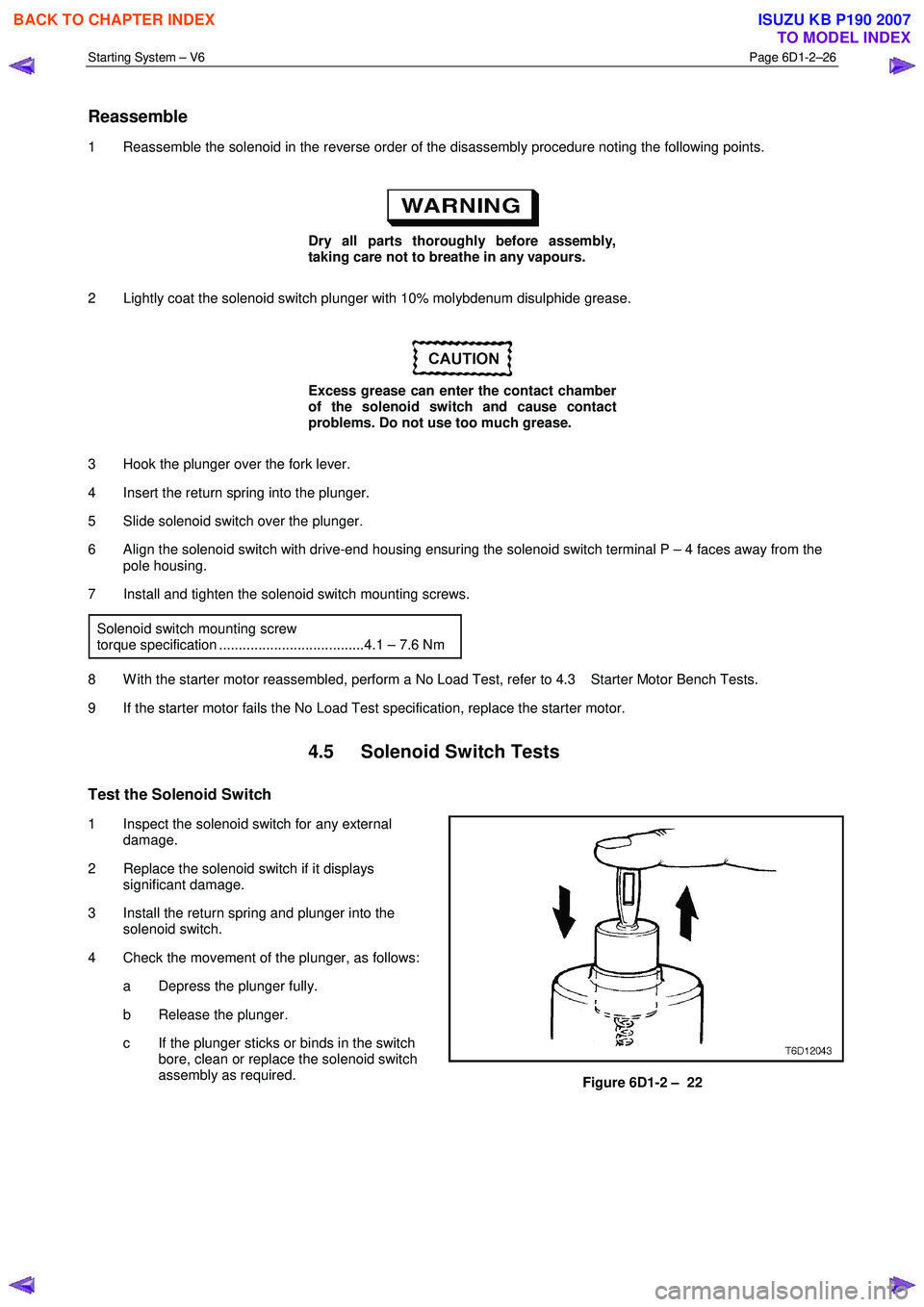
1 Inspect the solenoid switch for any external damage.
2 Replace the solenoid switch if it displays significant damage.
3 Install the return spring and plunger into the solenoid switch.
4 Check the movement of the plunger, as follows: a Depress the plunger fully.
b Release the plunger.
c If the plunger sticks or binds in the switch bore, clean or replace the solenoid switch
assembly as required.
Figure 6D1-2 – 22
BACK TO CHAPTER INDEX
TO MODEL INDEX
ISUZU KB P190 2007
Page 3643 of 6020
Battery Page 6D1-3–3
1 General Information
The vehicle is fitted with a 12 V battery located in the front right-hand corner of the engine compartment. The battery
provides:
• power for cranking the engine,
• power for a limited time when the electrical load exceeds the generator output,
• power for the accessories when the engine is not running, and
• a voltage stabilising load for the electrical system.
1.1 WARNING, CAUTION and NOTES
This Section contains various W ARNINGS, CAUTIONS and NOTE statements that you must observe carefully to reduce
the risk of death or injury during service, repair procedures or vehicle operation. Incorrect service or repair procedures
may damage the vehicle or cause operational faults. W ARNINGS, CAUTION and NOTE statements are not exhaustive.
HOLDEN LTD can not possibly warn of all the potentially hazardous consequences of failure to follow these instructions.
Definition of WARNING, CAUTION and NOTE Statements
Diagnosis and repair procedures in this Section contain both general and specific W ARNING, CAUTION and NOTE
statements. HOLDEN LTD is dedicated to the presentation of service information that helps the technician to diagnose
and repair the systems necessary for proper operation of the vehicle. Certain procedures may present a hazard to the
technician if they are not followed in the recommended manner. W ARNING, CAUTION and NOTE statements are
designed to help prevent these hazards from occurring, but not all hazards can be foreseen.
WARNING defined
A W ARNING statement immediately precedes an operating procedure or maintenance practice which, if not correctly
followed, could result in death or injury. A W ARNING statement alerts you to take necessary action or not to take a
prohibited action. If a W ARNING statement is ignored, the following consequences may occur:
• Death or injury to the technician or other personnel working on the vehicle,
• Death or injury to other people in or near the workplace area, and / or
• Death or injury to the driver / or passenger(s) of the vehicle or other people, if the vehicle has been improperly
repaired.
CAUTION defined
A CAUTION statement immediately precedes an operating procedure or maintenance practice which, if not correctly
followed, could result in damage to or destruction of equipment, or corruption of data. If a CAUTION statement is ignored,
the following consequences may occur:
• Damage to the vehicle,
• Unnecessary vehicle repairs or component replacement,
• Faulty operation or performance of any system or component being repaired,
• Damage to any system or components which depend on the proper operation of the system or component being
repaired,
• Faulty operation or performance of any systems or components which depend on the proper operation or
performance of the system or component under repair,
• Damage to fasteners, basic tools or special tools and / or
• Leakage of coolant, lubricant or other vital fluids.
NOTE defined
A NOTE statement immediately precedes or follows an operating procedure, maintenance practice or condition that
requires highlighting. A NOTE statement also emphasises necessary characteristics of a diagnostic or repair procedure.
A NOTE statement is designed to:
BACK TO CHAPTER INDEX
TO MODEL INDEX
ISUZU KB P190 2007
Page 3646 of 6020
Battery Page 6D1-3–6
2 Safety Precautions
• Battery fluid contains sulphuric acid,
which can cause serious injury. Do not
allow liquid from the battery to contact
eyes or skin. If contact occurs, flush the
area immediately with running water and
contact a physician.
• Lead acid batteries produce explosive
gases. Keep sparks, flames and lighted
cigarettes away from the battery,
especially when the battery is being
charged. Failure to follow this warning
could result in a battery explosion.
• Metal objects that touch a battery terminal
can produce sparks that can cause
serious burns. When working near a
battery, take extra care with metal objects
including tools and items of jewellery,
especially rings and metal watchbands.
Do not allow liquid from the battery to contact
clothing or painted surfaces. If contact occurs,
flush the area immediately with running water.
W hen working with or near the battery, always:
• W ear safety glasses and work gloves.
• Remove items of jewellery such as rings and metal watchbands.
• Ensure the ignition is switched off when connecting or disconnecting battery cables, battery charging equipment or
battery jumper cables. Failing to do so can damage the vehicle electronic components.
• Disconnect the negative battery cable before disconnecting the positive cable from the battery. Inversely, connect
the positive battery cable to the battery before connecting the negative cable. This reduces the possibility of
shorting the battery to ground while working near the positive connections.
BACK TO CHAPTER INDEX
TO MODEL INDEX
ISUZU KB P190 2007
Page 3648 of 6020
Battery Page 6D1-3–8
Step Action Yes No
5
Perform the hydrometer test, refer to 3.3 Hydrometer Test.
Is the battery fully charged? Go to Step 6 Fully charge the
battery, refer to 4.2 Battery
Charge
6 Load test the battery, refer to 3.4 Load Test.
Does the battery pass the load test? Battery Serviceable.
Refer to:
6D1–1 Charging System – V6. Replace the battery,
refer to 4.1
Battery
When all diagnosis and repairs are completed, check the system for correct operation.
3.2 Battery Inspection
1 Read and obey the safety precautions for working with batteries, refer to 2 Safety Precautions.
2 Check the battery terminals and around the battery area for corrosion deposits. Remove any deposits as follows: a Scrub the area with a stiff brush.
b Treat the area with a solution of warm water and baking soda or ammonia.
c Rinse with clean water.
3 Check the battery posts, if they are loose, burned, pitted or damaged in any way replace the battery. Refer to 4.1 Battery.
4 Check the battery case, if it is cracked or damaged replace the battery. Refer to 4.1 Battery.
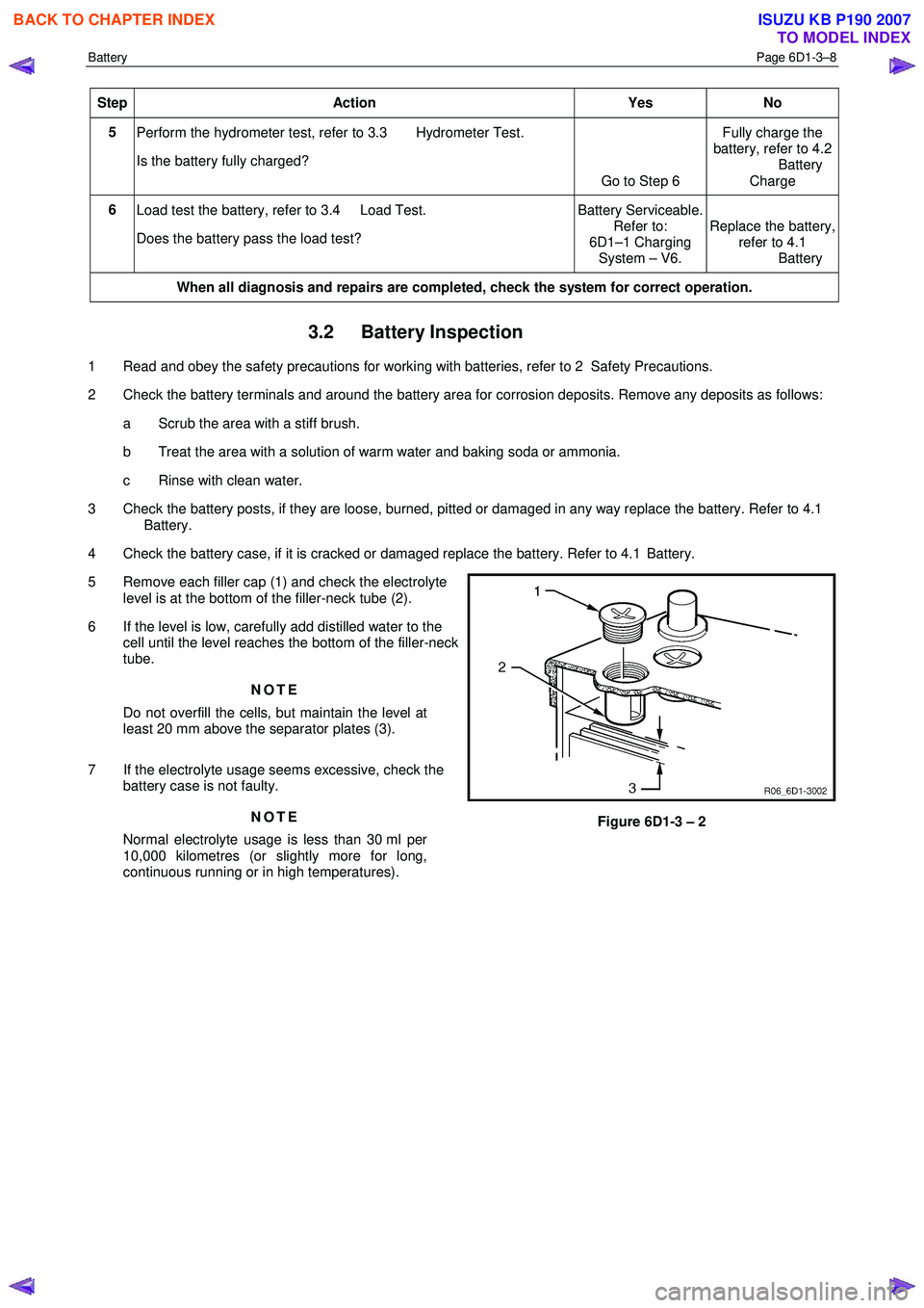
5 Remove each filler cap (1) and check the electrolyte level is at the bottom of the filler-neck tube (2).
6 If the level is low, carefully add distilled water to the cell until the level reaches the bottom of the filler-neck
tube.
NOTE
Do not overfill the cells, but maintain the level at
least 20 mm above the separator plates (3).
7 If the electrolyte usage seems excessive, check the battery case is not faulty.
NOTE
Normal electrolyte usage is less than 30 ml per
10,000 kilometres (or slightly more for long,
continuous running or in high temperatures).
Figure 6D1-3 – 2
BACK TO CHAPTER INDEX
TO MODEL INDEX
ISUZU KB P190 2007