2007 ISUZU KB P190 light
[x] Cancel search: lightPage 3137 of 6020
Engine Cooling – V6 Engine Page 6B1–2
Cooling System Pressure Testing ................................................................................................ ...................... 32
3.8 Thermostat ........................................................................................................................................................... 34
Remove ................................................................................................................................................................. 34
Test ....................................................................................................................................................................... 37
Dismantle ...................................................................................................................... ........................................ 37
Reassembly .......................................................................................................................................................... 37
Install .................................................................................................................................................................... 38
3.9 Coolant Recovery Reservoir ..................................................................................................... .......................... 39
Remove ................................................................................................................................................................. 39
Inspect .................................................................................................................................................................. 39
Install .................................................................................................................................................................... 39
3.10 Coolant Pump................................................................................................................... .................................... 40
Remove ................................................................................................................................................................. 40
Inspect .................................................................................................................................................................. 43
Reinstall ................................................................................................................................................................ 43
3.11 Coolant Outlet Housing ......................................................................................................... .............................. 45
Remove ................................................................................................................................................................. 45
Reinstall ................................................................................................................................................................ 46
3.12 Coolant Inlet Pipe............................................................................................................. .................................... 46
Remove ................................................................................................................................................................. 46
Install .................................................................................................................................................................... 48
3.13 Cooling Fan and Shroud Assembly ................................................................................................ ................... 48
Remove ................................................................................................................................................................. 48
Install .................................................................................................................................................................... 50
Disassemble ......................................................................................................................................................... 51
Reassemble .......................................................................................................................................................... 51
3.14 Flexible Transmission Cooler Hose .............................................................................................. ..................... 51
Replace ................................................................................................................................................................. 51
Reinstall ................................................................................................................................................................ 53
3.15 Radiator ....................................................................................................................... ......................................... 54
Remove ......................................................................................................................... ........................................ 54
Reinstall ................................................................................................................................................................ 56
Radiator Repair Procedure...................................................................................................... ............................ 57
Repairable Leaks ............................................................................................................................................. 57
Repair Method.................................................................................................................................................. 58
Tube Blocking................................................................................................................................................... 58
Header Repair .................................................................................................................. ................................ 58
General Core Repair ............................................................................................................ ............................ 59
Transmission Oil Cooler Leak Test .............................................................................................. .................... 60
Transmission Oil Cooler Seal Replacement. ...................................................................................... .............. 60
4 Engine Cooling System Diagnosis .....................................................................................................61
4.1 Poor Heater Operation......................................................................................................................................... 61
4.2 Leaking Cylinder Head Gasket ................................................................................................... ........................ 61
4.3 Question the Customer ....................................................................................................................................... 61
4.4 Diagnostic Chart .................................................................................................................................................. 61
4.5 Problems Not Requiring Disassembly of Cooling System ........................................................................... .... 63
4.6 Problems Requiring Disassembly of Cooling System ...................................................................................... 63
4.7 Black Light and Dye Leak Diagnosis Method .................................................................................................... 63
5 Specifications .......................................................................................................................................64
6 Torque Wrench Specifications................................................................................................... .........66
7 Special Tools ........................................................................................................................................67
BACK TO CHAPTER INDEX
TO MODEL INDEX
ISUZU KB P190 2007
Page 3139 of 6020
Engine Cooling – V6 Engine Page 6B1–4
1.1 WARNING, CAUTION and NOTES
This Section contains various W ARNINGS, CAUTIONS and NOTE statements that you must observe carefully to reduce
the risk of death or injury during service, repair procedures or vehicle operation. Incorrect service or repair procedures
may damage the vehicle or cause operational faults. W ARNINGS, CAUTION and NOTE statements are not exhaustive.
HOLDEN LTD can not possibly warn of all the potentially hazardous consequences of failure to follow these instructions.
1.2 Definition of WARNING, CAUTION and NOTE Statements
Diagnosis and repair procedures in this Section contain both general and specific W ARNING, CAUTION and NOTE
statements. HOLDEN LTD is dedicated to the presentation of service information that helps the technician to diagnose
and repair the systems necessary for proper operation of the vehicle. Certain procedures may present a hazard to the
technician if they are not followed in the recommended manner. W ARNING, CAUTION and NOTE statements are
designed to help prevent these hazards from occurring, but not all hazards can be foreseen.
WARNING defined
A W ARNING statement immediately precedes an operating procedure or maintenance practice which, if not correctly
followed, could result in death or injury. A W ARNING statement alerts you to take necessary action or not to take a
prohibited action. If a W ARNING statement is ignored, the following consequences may occur:
• Death or injury to the technician or other personnel working on the vehicle,
• Death or injury to other people in or near the workplace area, and / or
• Death or injury to the driver / or passenger(s) of the vehicle or other people, if the vehicle has been improperly
repaired.
CAUTION defined
A CAUTION statement immediately precedes an operating procedure or maintenance practice which, if not correctly
followed, could result in damage to or destruction of equipment, or corruption of data. If a CAUTION statement is ignored,
the following consequences may occur:
• Damage to the vehicle,
• Unnecessary vehicle repairs or component replacement,
• Faulty operation or performance of any system or component being repaired,
• Damage to any system or components which depend on the proper operation of the system or component being
repaired,
• Faulty operation or performance of any systems or components which depend on the proper operation or
performance of the system or component under repair,
• Damage to fasteners, basic tools or special tools and / or
• Leakage of coolant, lubricant or other vital fluids.
NOTE defined
A NOTE statement immediately precedes or follows an operating procedure, maintenance practice or condition that
requires highlighting. A NOTE statement also emphasises necessary characteristics of a diagnostic or repair procedure.
A NOTE statement is designed to:
• Clarify a procedure,
• Present additional information for accomplishing a procedure,
• Give insight into the reasons for performing a procedure in the recommended manner, and / or
Present information that gives the technician the benefit of past experience in accomplishing a procedure with greater
ease.
BACK TO CHAPTER INDEX
TO MODEL INDEX
ISUZU KB P190 2007
Page 3148 of 6020
Engine Cooling – V6 Engine Page 6B1–13
2.6 Coolant Filler Cap
Figure 6B1 – 10 Figure 6B1 – 11
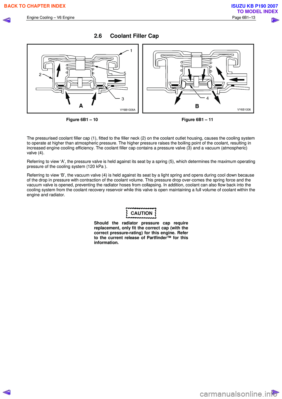
The pressurised coolant filler cap (1), fitted to the filler neck (2) on the coolant outlet housing, causes the cooling system
to operate at higher than atmospheric pressure. The higher pressure raises the boiling point of the coolant, resulting in
increased engine cooling efficiency. The coolant filler cap contains a pressure valve (3) and a vacuum (atmospheric)
valve (4).
Referring to view ‘A’, the pressure valve is held against its seat by a spring (5), which determines the maximum operating
pressure of the cooling system (120 kPa ).
Referring to view ‘B’, the vacuum valve (4) is held against its seat by a light spring and opens during cool down because
of the drop in pressure with contraction of the coolant volume. This pressure drop over-comes the spring force and the
vacuum valve is opened, preventing the radiator hoses from collapsing. In addition, coolant can also flow back into the
cooling system from the coolant recovery reservoir while this valve is open maintaining a full volume of coolant within the
engine and radiator.
Should the radiator pressure cap require
replacement, only fit the correct cap (with the
correct pressure-rating) for this engine. Refer
to the current release of Partfinder™ for this
information.
BACK TO CHAPTER INDEX
TO MODEL INDEX
ISUZU KB P190 2007
Page 3154 of 6020
Engine Cooling – V6 Engine Page 6B1–19
a Place a few drops of distilled water (between 21 and 29° C) onto the measuring window, then close the
plastic cover.
b Point the tester toward any light source, look into the eyepiece and check that the indicated reading is zero. If not, then re-calibrate the tester as detailed at the end of this Test Method, Calibrating the Tester.
2 Release the tip of the bulb pump from under the refractometer body. It is not necessary to remove the
complete pump from the tool.
Refer to 3.1 Service Notes in this
Section, for important safety items.
3 Carefully remove the coolant filler cap.
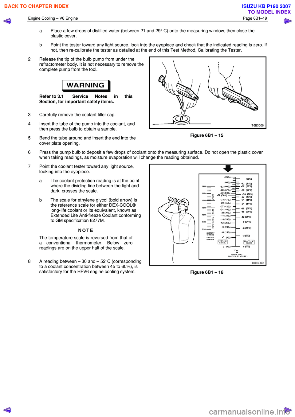
4 Insert the tube of the pump into the coolant, and then press the bulb to obtain a sample.
5 Bend the tube around and insert the end into the cover plate opening.
Figure 6B1 – 15
6 Press the pump bulb to deposit a few drops of coolant onto the measuring surface. Do not open the plastic cover when taking readings, as moisture evaporation will change the reading obtained.
7 Point the coolant tester toward any light source, looking into the eyepiece.
a The coolant protection reading is at the point where the dividing line between the light and
dark, crosses the scale.
b The scale for ethylene glycol (bold arrow) is the reference scale for either DEX-COOL®
long-life coolant or its equivalent, known as
Extended Life Anti-freeze Coolant conforming
to GM specification 6277M.
NOTE
The temperature scale is reversed from that of
a conventional thermometer. Below zero
readings are on the upper half of the scale.
8 A reading between – 30 and – 52 °C (corresponding
to a coolant concentration between 45 to 60%), is
satisfactory for the HFV6 engine cooling system.
Figure 6B1 – 16
BACK TO CHAPTER INDEX
TO MODEL INDEX
ISUZU KB P190 2007
Page 3167 of 6020
Engine Cooling – V6 Engine Page 6B1–32
4 Attach coolant filler cap (2) to a commercially
available cooling system pressure tester (1), using
the pressure cap adaptor.
5 Slowly pressurise cap to 120 – 130 kPa. The cap is serviceable if it unloads slightly above this pressure
range and holds pressure at 120 kPa.
NOTE
Should the cap fail to reach or hold the
specified pressure, replace the cap.
Figure 6B1 – 30
6 Prior to installing coolant filler cap ensure that the coolant filler neck cap seating surface is clean and
free from obstruction.
Figure 6B1 – 31
Cooling System Pressure Testing
Refer to 3.1 Service Notes in this Section, for
important safety items.
1 Allow the engine to cool to ambient temperature (less than 50 ° C), then remove coolant filler cap.
2 Ensure that the coolant level is correct.
BACK TO CHAPTER INDEX
TO MODEL INDEX
ISUZU KB P190 2007
Page 3168 of 6020
Engine Cooling – V6 Engine Page 6B1–33
3 Install the coolant filler neck adaptor, to a
commercially available cooling system pressure tester
(1).
4 Install the assembly to the engine coolant filler neck.
5 Using compressed air, blow dry any spilled coolant around coolant filler neck.
Do not exceed the stated pressure, as
damage to the cooling system could
otherwise result.
6 Using the cooling system pressure tester pump, pressurise cooling system to 130 kPa absolute
maximum and check for leaks at the following points:
• All hoses and hose connections
• Overflow hose connection at coolant outlet
housing connection
Figure 6B1 –
––
–
32
• Radiator seams and core
• Corroded or faulty engine W elch plugs
• Coolant pump and gasket
• Thermostat housing and coolant inlet pipe connection
• Radiator drain tap and bleed screw
• Vehicle heating system (e.g. heater core and water valve)
NOTE
For heater Removal and Installation, refer to 2A –
Heater and Air-conditioning.
7 Check engine oil dipstick for evidence of engine oil contamination with coolant.
8 If pressure will not hold, there is a leak in the cooling system. Repair as necessary.
NOTE
If visible loss of coolant is not evident from
pressure testing, then the use of a dye and black
light, may be necessary. Refer to 4.7 Black
Light and Dye Leak Diagnosis Method, in this
Section.
BACK TO CHAPTER INDEX
TO MODEL INDEX
ISUZU KB P190 2007
Page 3177 of 6020
Engine Cooling – V6 Engine Page 6B1–42
5 Drain the coolant from the system. Refer to 3.3
Draining and Filling Cooling System in this
Section.
6 Remove the four coolant pump pulley attaching bolts (1), then remove the pulley (2) from the
hub (3).
Figure 6B1 – 45
7 Remove the six coolant pump attaching bolts (1) from the coolant pump (2).
Figure 6B1 – 46
8 Remove the coolant pump (1) from the engine front cover.
NOTE
If necessary, use a soft-faced hammer to
lightly tap coolant pump housing to separate it
from front cover.
9 Remove coolant pump to front cover gasket (2) and discard.
Figure 6B1 – 47
BACK TO CHAPTER INDEX
TO MODEL INDEX
ISUZU KB P190 2007
Page 3198 of 6020
Engine Cooling – V6 Engine Page 6B1–63
4.5 Problems Not Requiring Disassembly of
Cooling System
1 Large obstructions blocking radiator or condenser airflow.
• Auxiliary oil coolers
• License plate
• Obstruction of radiator grille, for example, driving lights or mud
2 Loose, damaged or missing air chute side panels.
3 Missing or damaged air baffle.
4 Cracked or loose coolant recovery system hose.
5 Leaking heater component such as the heater core or water valve.
4.6 Problems Requiring Disassembly of Cooling System
1 Damaged cooling fan or faulty motor operation.
2 Pressure test cooling system.
3 Defective coolant pump.
• Eroded or broken impeller vanes
• Failed bearing or seal – check for shaft or bearing end play
4 Internally blocked radiator core.
5 Obstruction of coolant recovery system.
6 Internal system leaks.
• Head gaskets
• Cracked cylinder block
• Engine front cover
• Intake manifold gaskets
7 Blocked coolant passages in cylinder heads or block – remove cylinder heads and check.
4.7 Black Light and Dye Leak Diagnosis Method
It is strongly recommended that this diagnostic method be used to diagnose fluid leaks. This method is a proven and
reliable method that identifies the specific leak source.
The black light kit can be used for the leak detection of a number of fluids, when used with the appropriate tracer dye.
Examples are: Coolant, Engine Oil, Automatic Transmission Fluid and Air Conditioning Refrigerant (R134A).
The following is a summary of the steps involved in detecting a cooling system fluid leak using black light and dye:
1 Pour specified amount of dye into the cooling system via the coolant filler cap on the outlet housing. Refer 3.1 Service Notes in this Section.
2 Road test the vehicle under normal operating conditions.
3 Direct the light towards the suspect area. The fluid leak will appear as a brightly coloured path leading from the source.
4 Repair fluid leak and recheck to ensure that leak has been rectified.
5 Refer to the manufacturer’s directions when using this method.
BACK TO CHAPTER INDEX
TO MODEL INDEX
ISUZU KB P190 2007