2007 ISUZU KB P190 light
[x] Cancel search: lightPage 2726 of 6020
Engine Mechanical – V6 Page 6A1–247
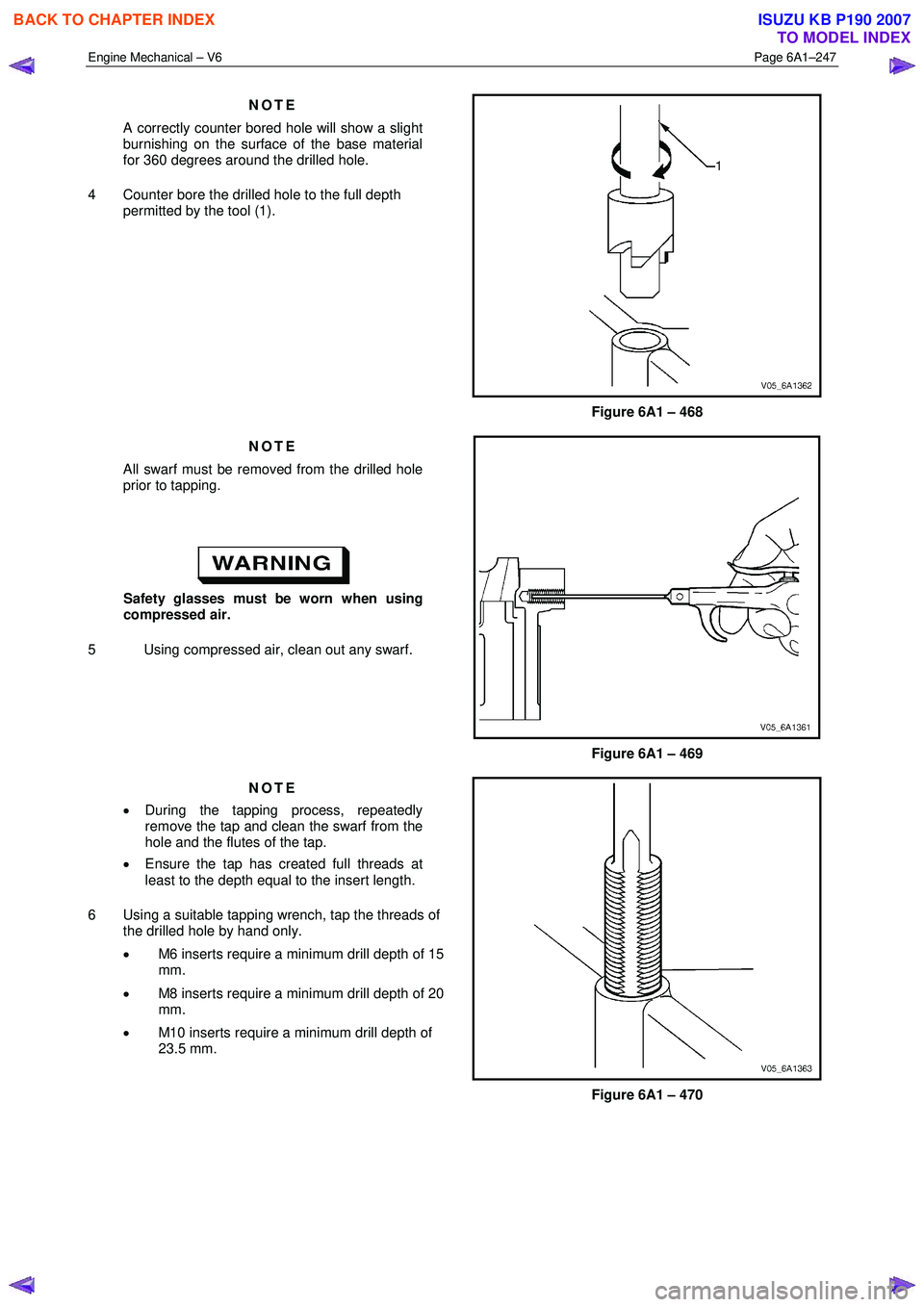
NOTE
A correctly counter bored hole will show a slight
burnishing on the surface of the base material
for 360 degrees around the drilled hole.
4 Counter bore the drilled hole to the full depth permitted by the tool (1).
Figure 6A1 – 468
NOTE
All swarf must be removed from the drilled hole
prior to tapping.
Safety glasses must be worn when using
compressed air.
5 Using compressed air, clean out any swarf.
Figure 6A1 – 469
NOTE
• During the tapping process, repeatedly
remove the tap and clean the swarf from the
hole and the flutes of the tap.
• Ensure the tap has created full threads at
least to the depth equal to the insert length.
6 Using a suitable tapping wrench, tap the threads of the drilled hole by hand only.
• M6 inserts require a minimum drill depth of 15
mm.
• M8 inserts require a minimum drill depth of 20
mm.
• M10 inserts require a minimum drill depth of
23.5 mm.
Figure 6A1 – 470
BACK TO CHAPTER INDEX
TO MODEL INDEX
ISUZU KB P190 2007
Page 2730 of 6020
Engine Mechanical – V6 Page 6A1–251
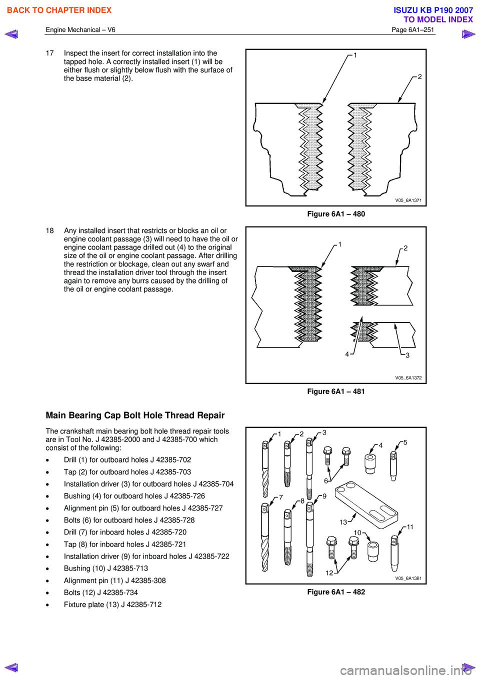
17 Inspect the insert for correct installation into the
tapped hole. A correctly installed insert (1) will be
either flush or slightly below flush with the surface of
the base material (2).
Figure 6A1 – 480
18 Any installed insert that restricts or blocks an oil or engine coolant passage (3) will need to have the oil or
engine coolant passage drilled out (4) to the original
size of the oil or engine coolant passage. After drilling
the restriction or blockage, clean out any swarf and
thread the installation driver tool through the insert
again to remove any burrs caused by the drilling of
the oil or engine coolant passage.
Figure 6A1 – 481
Main Bearing Cap Bolt Hole Thread Repair
The crankshaft main bearing bolt hole thread repair tools
are in Tool No. J 42385-2000 and J 42385-700 which
consist of the following:
• Drill (1) for outboard holes J 42385-702
• Tap (2) for outboard holes J 42385-703
• Installation driver (3) for outboard holes J 42385-704
• Bushing (4) for outboard holes J 42385-726
• Alignment pin (5) for outboard holes J 42385-727
• Bolts (6) for outboard holes J 42385-728
• Drill (7) for inboard holes J 42385-720
• Tap (8) for inboard holes J 42385-721
• Installation driver (9) for inboard holes J 42385-722
• Bushing (10) J 42385-713
• Alignment pin (11) J 42385-308
• Bolts (12) J 42385-734
• Fixture plate (13) J 42385-712
Figure 6A1 – 482
BACK TO CHAPTER INDEX
TO MODEL INDEX
ISUZU KB P190 2007
Page 2779 of 6020
Engine Mechanical – V6 Page 6A1–2
Page 6A1–2
Visual / Physical Inspection ................................................................................................... .............................31
Intermittent ................................................................................................................... ........................................31
2.3 Engine Misfire without In ternal Engine Noises .................................................................................. ...............32
2.4 Engine Misfire with Abnormal In ternal Lower Engine Noises...................................................................... ....34
2.5 Engine Misfire with Abno rmal Valve Train Noise ................................................................................. .............35
2.6 Engine Misfire with Coolant Consumption ........................................................................................ ................36
2.7 Engine Misfire with E xcessive Oil Consumption .................................................................................. ............37
2.8 Engine Noise on Start-up, but only Lasting a Few Seconds ....................................................................... .....38
2.9 Upper Engine Noise, Rega rdless of Engine Speed................................................................................. ..........39
2.10 Lower Engine Noise, Rega rdless of Engine Speed ................................................................................. .........40
2.11 Engine Noise Under Load ................................................................................................................................... 41
2.12 Engine Will Not Crank – Crankshaft Will Not Rotate ............................................................................. ...........42
2.13 Coolant in Com bustion Chamber .................................................................................................. .....................43
Definition ..................................................................................................................... .........................................43
2.14 Coolant in Engine Oil........................................................................................................................................... 44
Definition ..............................................................................................................................................................44
2.15 Engine Compression Test........................................................................................................ ...........................45
Preliminary Steps................................................................................................................................................. 45
Engine Cylinder Compression Test ............................................................................................... ....................45
Test Result Evaluation ......................................................................................................... ...............................45
2.16 Cylinder Leakage Test .......................................................................................................... ...............................46
2.17 Engine Oil Consumption Diagnosis ............................................................................................... ....................47
Definition ..................................................................................................................... .........................................47
2.18 Engine Oil Leak Diagnosis .................................................................................................................................. 48
Introduction ..........................................................................................................................................................48
Locating and Identifying the Leak .............................................................................................. ........................48
Visual Inspection .............................................................................................................. ...................................48
Powder Method .................................................................................................................. ..................................48
Black Light and Dye Method ............................................................................................................................... 48
Possible Causes for Engine Oil Leaks ........................................................................................... ....................49
2.19 Engine Oil Pressu re Diagnosis .................................................................................................. .........................50
2.20 Accessory Drive Belt Diagnosis ................................................................................................. ........................51
Tension Check .................................................................................................................. ...................................51
Inspect ........................................................................................................................ ..........................................52
Drive Belt Chirp .................................................................................................................................................... 53
Definition ..................................................................................................................... .....................................53
Diagnostic Aids................................................................................................................................................. 53
Test Description ............................................................................................................... ................................53
Diagnostic Table............................................................................................................... ................................54
Drive Belt Squeal .............................................................................................................. ...................................55
Definition ..................................................................................................................... .....................................55
Diagnostic Aids................................................................................................................................................. 55
Test Description ............................................................................................................... ................................55
Diagnostic Table............................................................................................................... ................................55
Drive Belt Whine .................................................................................................................................................. 57
Definition ..................................................................................................................... .....................................57
Diagnostic Aids................................................................................................................................................. 57
Test Description ............................................................................................................... ................................57
Diagnostic Table............................................................................................................... ................................57
Drive Belt Rumble .............................................................................................................. ..................................58
Definition ..................................................................................................................... .....................................58
Diagnostic Aids................................................................................................................................................. 58
Test Description ............................................................................................................... ................................58
Diagnostic Table............................................................................................................... ................................58
Drive Belt Vibration........................................................................................................... ...................................60
Definition ..................................................................................................................... .....................................60
Diagnostic Aids................................................................................................................................................. 60
Test Description ............................................................................................................... ................................60
Diagnostic Table............................................................................................................... ................................60
Drive Belt Falls Off ........................................................................................................... ....................................62
BACK TO CHAPTER INDEX
TO MODEL INDEX
ISUZU KB P190 2007
Page 2786 of 6020
Engine Mechanical – V6 Page 6A1–9
Page 6A1–9
• Faulty operation or performance of any system or component being repaired,
• Damage to any system or components which depend on the proper operation of the system or component being
repaired,
• Faulty operation or performance of any systems or components which depend on the proper operation or
performance of the system or component under repair,
• Damage to fasteners, basic tool s or special tools and / or
• Leakage of coolant, lubricant or other vital fluids.
NOTE defined
A NOTE statement immediatel y precedes or follows an operating procedure, maintenance practice or condition that
requires highlighting. A NOTE statement also emphasises necessary characte ristics of a diagnostic or repair procedure.
A NOTE statement is designed to:
• Clarify a procedure,
• Present additional information for accomplishing a procedure,
• Give insight into the reasons for performi ng a procedure in the recommended manner, and / or
Present information that gives the tec hnician the benefit of past experience in accomplishing a procedure with greater
ease.
BACK TO CHAPTER INDEX
TO MODEL INDEX
ISUZU KB P190 2007
Page 2806 of 6020
Engine Mechanical – V6 Page 6A1–29
Page 6A1–29
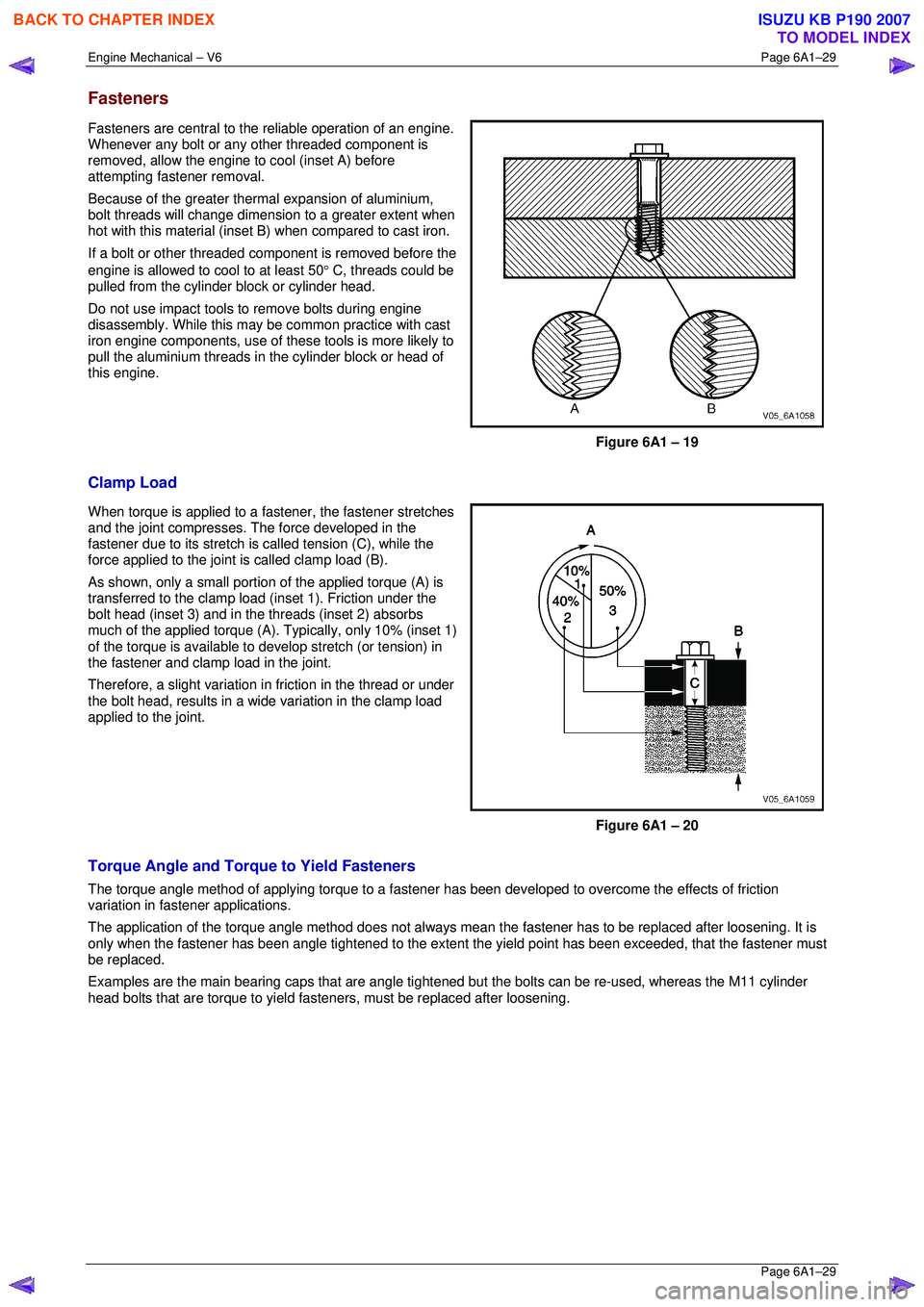
Fasteners
Fasteners are central to the reliable operation of an engine.
Whenever any bolt or any other threaded component is
removed, allow the engine to cool (inset A) before
attempting fastener removal.
Because of the greater the rmal expansion of aluminium,
bolt threads will change dimensi on to a greater extent when
hot with this material (inset B) when compared to cast iron.
If a bolt or other threaded com ponent is removed before the
engine is allowed to cool to at least 50 ° C, threads could be
pulled from the cylinder block or cylinder head.
Do not use impact tools to remove bolts during engine
disassembly. While this may be common practice with cast
iron engine components, use of thes e tools is more likely to
pull the aluminium threads in the cylinder block or head of
this engine.
Figure 6A1 – 19
Clamp Load
When torque is applied to a fa stener, the fastener stretches
and the joint compresses. The force developed in the
fastener due to its stretch is called tension (C), while the
force applied to the joint is called clamp load (B).
As shown, only a small portion of the applied torque (A) is
transferred to the clamp load (inset 1). Friction under the
bolt head (inset 3) and in the threads (inset 2) absorbs
much of the applied torque (A). Typically, only 10% (inset 1)
of the torque is available to develop stretch (or tension) in
the fastener and clamp load in the joint.
Therefore, a slight variation in friction in the thread or under
the bolt head, results in a wide variation in the clamp load
applied to the joint.
Figure 6A1 – 20
Torque Angle and Torque to Yield Fasteners
The torque angle method of applying torque to a fastener has been developed to overcome the effects of friction
variation in fastener applications.
The application of the torque angle method does not always mean the fastener has to be replaced after loosening. It is
only when the fastener has been angle tightened to the extent the yield point has been exceeded, that the fastener must
be replaced.
Examples are the main bearing caps that are angle tightened but the bolts can be re-used, whereas the M11 cylinder
head bolts that are torque to yield fasteners, must be replaced after loosening.
BACK TO CHAPTER INDEX
TO MODEL INDEX
ISUZU KB P190 2007
Page 2810 of 6020
Engine Mechanical – V6 Page 6A1–33
Page 6A1–33
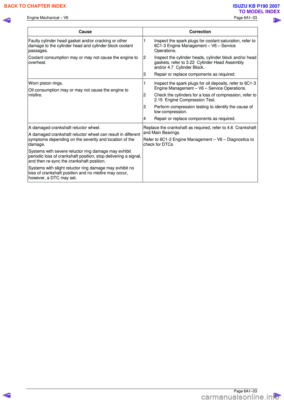
Cause Correction
Faulty cylinder head gasket and/or cracking or other
damage to the cylinder head and cylinder block coolant
passages.
Coolant consumption may or may not cause the engine to
overheat. 1 Inspect the spark plugs for
coolant saturation, refer to
6C1-3 Engine Management – V6 – Service
Operations.
2 Inspect the cylinder heads, cylinder block and/or head gaskets, refer to 3.22 Cylinder Head Assembly
and/or 4.7 Cylinder Block.
3 Repair or replace components as required.
Worn piston rings.
Oil consumption may or ma y not cause the engine to
misfire. 1 Inspect the spark plugs for oil deposits, refer to 6C1-3
Engine Management – V6 – Service Operations.
2 Check the cylinders for a loss of compression, refer to 2.15 Engine Compression Test.
3 Perform compression testing to identify the cause of
low compression.
4 Repair or replace components as required.
A damaged crankshaft reluctor wheel.
A damaged crankshaft reluctor wheel can result in different
symptoms depending on the severity and location of the
damage.
Systems with severe relu ctor ring damage may exhibit
periodic loss of crankshaft posit ion, stop delivering a signal,
and then re-sync the crankshaft position.
Systems with slight reluctor ring damage may exhibit no
loss of crankshaft position and no misfire may occur,
however, a DTC may set. Replace the crankshaft as required, refer to 4.6 Crankshaft
and Main Bearings.
Refer to 6C1-2 Engine Management – V6 – Diagnostics to
check for DTCs
BACK TO CHAPTER INDEX
TO MODEL INDEX
ISUZU KB P190 2007
Page 2815 of 6020
Engine Mechanical – V6 Page 6A1–38
Page 6A1–38
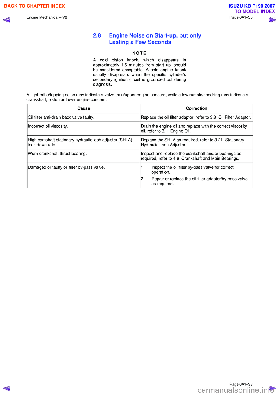
2.8 Engine Noise on Start-up, but only
Lasting a Few Seconds
NOTE
A cold piston knock, which disappears in
approximately 1.5 minutes from start up, should
be considered acceptable. A cold engine knock
usually disappears when t he specific cylinder’s
secondary ignition circuit is grounded out during
diagnosis.
A light rattle/tapping noise may indicate a valve train/upper engine concern, while a low rumble/knocking may indicate a
crankshaft, piston or lower engine concern.
Cause Correction
Oil filter anti-drain back valve faulty. Replace the o il filter adaptor, refer to 3.3 Oil Filter Adaptor.
Incorrect oil viscosity.
Drain the engine oil and replace with the correct viscosity
oil, refer to 3.1 Engine Oil.
High camshaft stationary hydraulic lash adjuster (SHLA)
leak down rate. Replace the SHLA as required,
refer to 3.21 Stationary
Hydraulic Lash Adjuster.
Worn crankshaft thrust bearing. Inspect and replace the crankshaft and/or bearings as
required, refer to 4.6 Crankshaft and Main Bearings.
Damaged or faulty oil filter by-pass valve. 1 Inspect the oil filter by-pass valve for correct
operation.
2 Repair or replace the oil filter adaptor/by-pass valve
as required.
BACK TO CHAPTER INDEX
TO MODEL INDEX
ISUZU KB P190 2007
Page 2816 of 6020
Engine Mechanical – V6 Page 6A1–39
Page 6A1–39
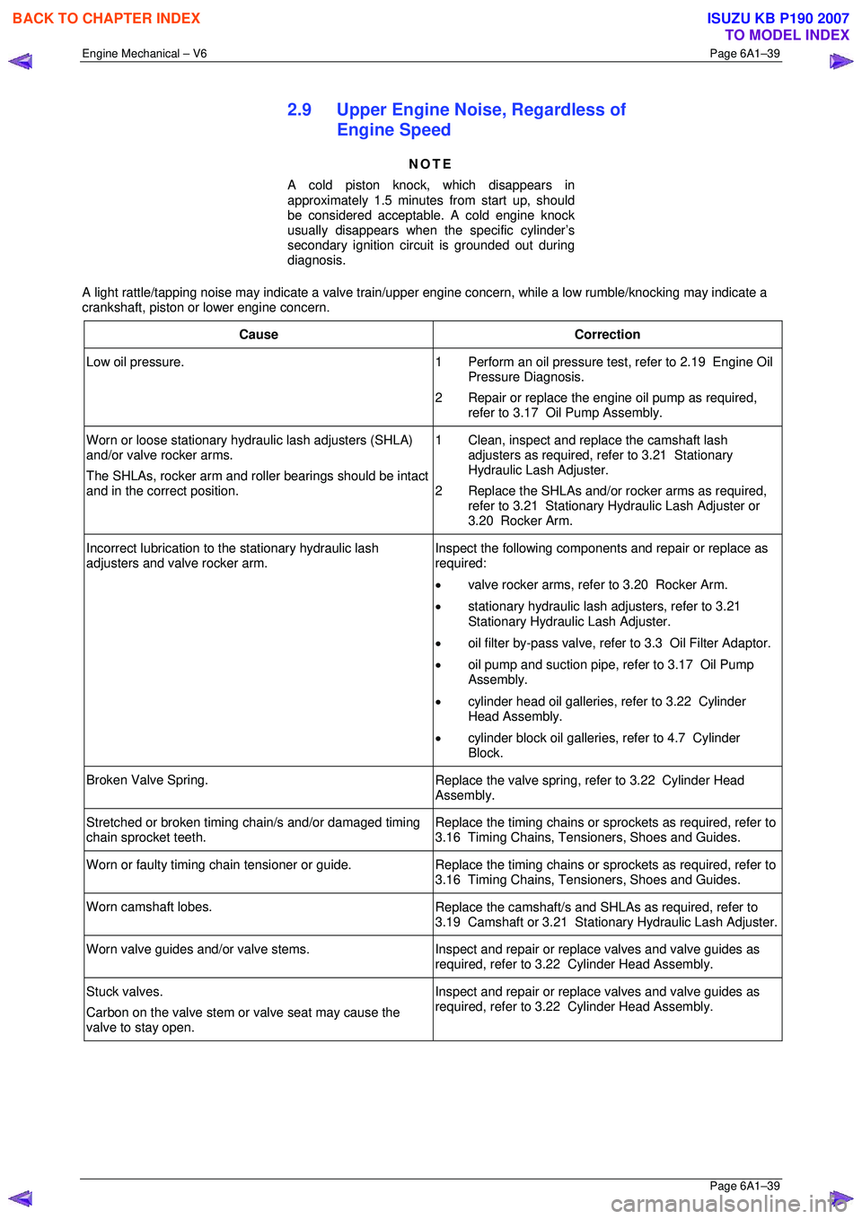
2.9 Upper Engine Noise, Regardless of
Engine Speed
NOTE
A cold piston knock, which disappears in
approximately 1.5 minutes from start up, should
be considered acceptable. A cold engine knock
usually disappears when t he specific cylinder’s
secondary ignition circuit is grounded out during
diagnosis.
A light rattle/tapping noise may indicate a valve train/upper engine concern, while a low rumble/knocking may indicate a
crankshaft, piston or lower engine concern.
Cause Correction
Low oil pressure. 1 Perform an oil pressure test, refer to 2.19 Engine Oil
Pressure Diagnosis.
2 Repair or replace the engine oil pump as required, refer to 3.17 Oil Pump Assembly.
Worn or loose stationary hydraulic lash adjusters (SHLA)
and/or valve rocker arms.
The SHLAs, rocker arm and roller bearings should be intact
and in the correct position. 1 Clean, inspect and replace the camshaft lash
adjusters as required, refer to 3.21 Stationary
Hydraulic Lash Adjuster.
2 Replace the SHLAs and/or rocker arms as required, refer to 3.21 Stationary Hydraulic Lash Adjuster or
3.20 Rocker Arm.
Incorrect lubrication to t he stationary hydraulic lash
adjusters and valve rocker arm. Inspect the following components and repair or replace as
required:
• valve rocker arms, refer to 3.20 Rocker Arm.
• stationary hydraulic lash adjusters, refer to 3.21
Stationary Hydraulic Lash Adjuster.
• oil filter by-pass valve, refe r to 3.3 Oil Filter Adaptor.
• oil pump and suction pipe, refer to 3.17 Oil Pump
Assembly.
• cylinder head oil galleries, refer to 3.22 Cylinder
Head Assembly.
• cylinder block oil galleries, refer to 4.7 Cylinder
Block.
Broken Valve Spring. Replace the valve spring, refer to 3.22 Cylinder Head
Assembly.
Stretched or broken timing chain/s and/or damaged timing
chain sprocket teeth. Replace the timing chains or sprockets as required, refer to
3.16 Timing Chains, Tensioners, Shoes and Guides.
Worn or faulty timing chain tensioner or guide. Replace the timing chains or sprockets as required, refer to
3.16 Timing Chains, Tensioners, Shoes and Guides.
Worn camshaft lobes. Replace the camshaft/s and SHLAs as required, refer to
3.19 Camshaft or 3.21 Stati onary Hydraulic Lash Adjuster.
Worn valve guides and/or valve stems.
Inspect and repair or replace valves and valve guides as
required, refer to 3.22 Cylinder Head Assembly.
Stuck valves.
Carbon on the valve stem or valve seat may cause the
valve to stay open. Inspect and repair or replace valves and valve guides as
required, refer to 3.22 Cylinder Head Assembly.
BACK TO CHAPTER INDEX
TO MODEL INDEX
ISUZU KB P190 2007