2007 ISUZU KB P190 light
[x] Cancel search: lightPage 2648 of 6020
Engine Mechanical – V6 Page 6A1–169
Valve Guide Measurement
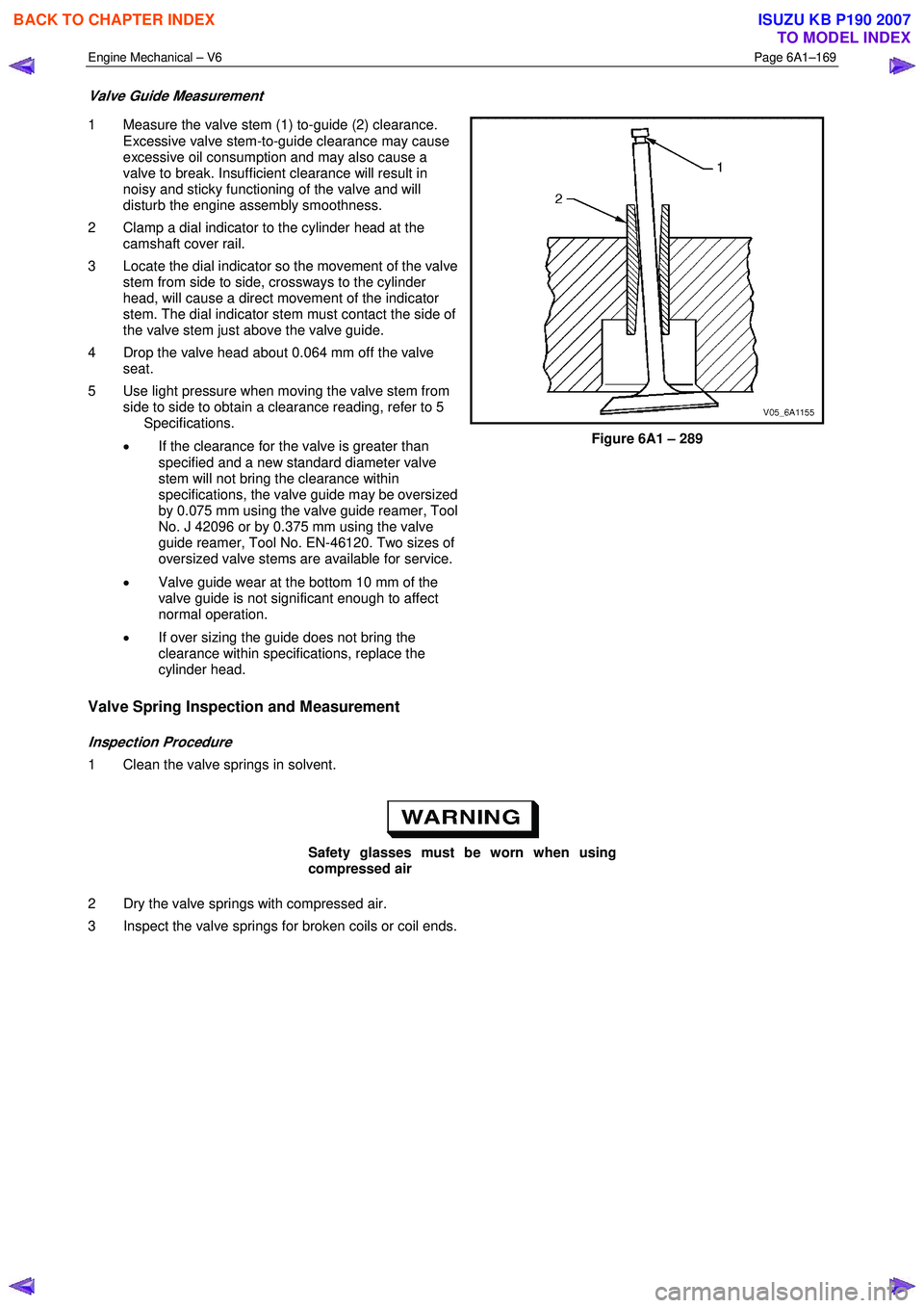
1 Measure the valve stem (1) to-guide (2) clearance.
Excessive valve stem-to-guide clearance may cause
excessive oil consumption and may also cause a
valve to break. Insufficient clearance will result in
noisy and sticky functioning of the valve and will
disturb the engine assembly smoothness.
2 Clamp a dial indicator to the cylinder head at the camshaft cover rail.
3 Locate the dial indicator so the movement of the valve stem from side to side, crossways to the cylinder
head, will cause a direct movement of the indicator
stem. The dial indicator stem must contact the side of
the valve stem just above the valve guide.
4 Drop the valve head about 0.064 mm off the valve seat.
5 Use light pressure when moving the valve stem from side to side to obtain a clearance reading, refer to 5
Specifications.
• If the clearance for the valve is greater than
specified and a new standard diameter valve
stem will not bring the clearance within
specifications, the valve guide may be oversized
by 0.075 mm using the valve guide reamer, Tool
No. J 42096 or by 0.375 mm using the valve
guide reamer, Tool No. EN-46120. Two sizes of
oversized valve stems are available for service.
• Valve guide wear at the bottom 10 mm of the
valve guide is not significant enough to affect
normal operation.
• If over sizing the guide does not bring the
clearance within specifications, replace the
cylinder head.
Figure 6A1 – 289
Valve Spring Inspection and Measurement
Inspection Procedure
1 Clean the valve springs in solvent.
Safety glasses must be worn when using
compressed air
2 Dry the valve springs with compressed air.
3 Inspect the valve springs for broken coils or coil ends.
BACK TO CHAPTER INDEX
TO MODEL INDEX
ISUZU KB P190 2007
Page 2650 of 6020
Engine Mechanical – V6 Page 6A1–171
Valve Seat Width Measurement Procedure
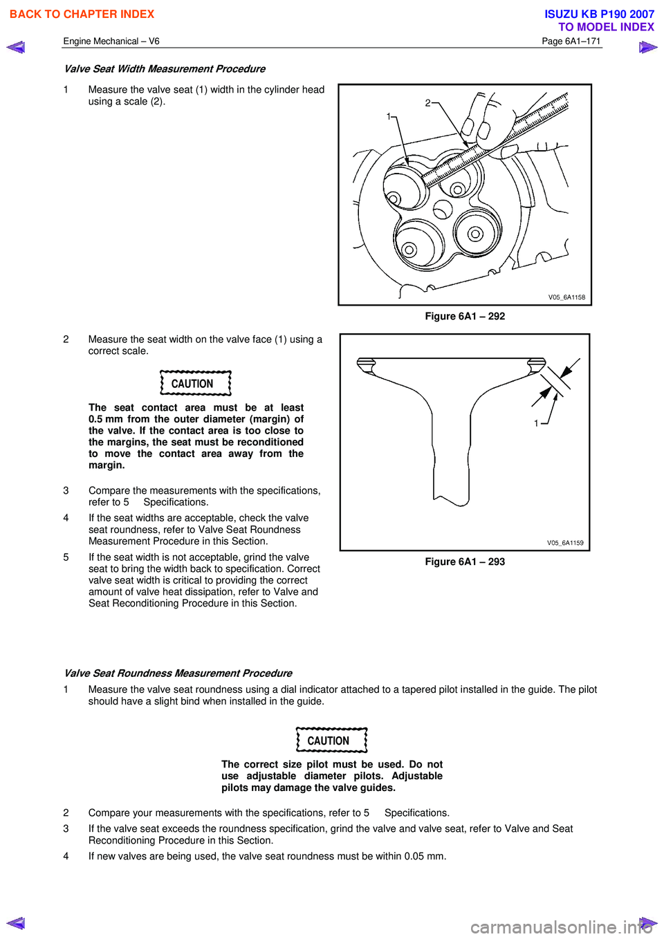
1 Measure the valve seat (1) width in the cylinder head
using a scale (2).
Figure 6A1 – 292
2 Measure the seat width on the valve face (1) using a correct scale.
CAUTION
The seat contact area must be at least
0.5 mm from the outer diameter (margin) of
the valve. If the contact area is too close to
the margins, the seat must be reconditioned
to move the contact area away from the
margin.
3 Compare the measurements with the specifications, refer to 5 Specifications.
4 If the seat widths are acceptable, check the valve seat roundness, refer to Valve Seat Roundness
Measurement Procedure in this Section.
5 If the seat width is not acceptable, grind the valve seat to bring the width back to specification. Correct
valve seat width is critical to providing the correct
amount of valve heat dissipation, refer to Valve and
Seat Reconditioning Procedure in this Section.
Figure 6A1 – 293
Valve Seat Roundness Measurement Procedure
1 Measure the valve seat roundness using a dial indicator attached to a tapered pilot installed in the guide. The pilot should have a slight bind when installed in the guide.
CAUTION
The correct size pilot must be used. Do not
use adjustable diameter pilots. Adjustable
pilots may damage the valve guides.
2 Compare your measurements with the specifications, refer to 5 Specifications.
3 If the valve seat exceeds the roundness specification, grind the valve and valve seat, refer to Valve and Seat Reconditioning Procedure in this Section.
4 If new valves are being used, the valve seat roundness must be within 0.05 mm.
BACK TO CHAPTER INDEX
TO MODEL INDEX
ISUZU KB P190 2007
Page 2651 of 6020
Engine Mechanical – V6 Page 6A1–172
Valve Margin Measurement Procedure
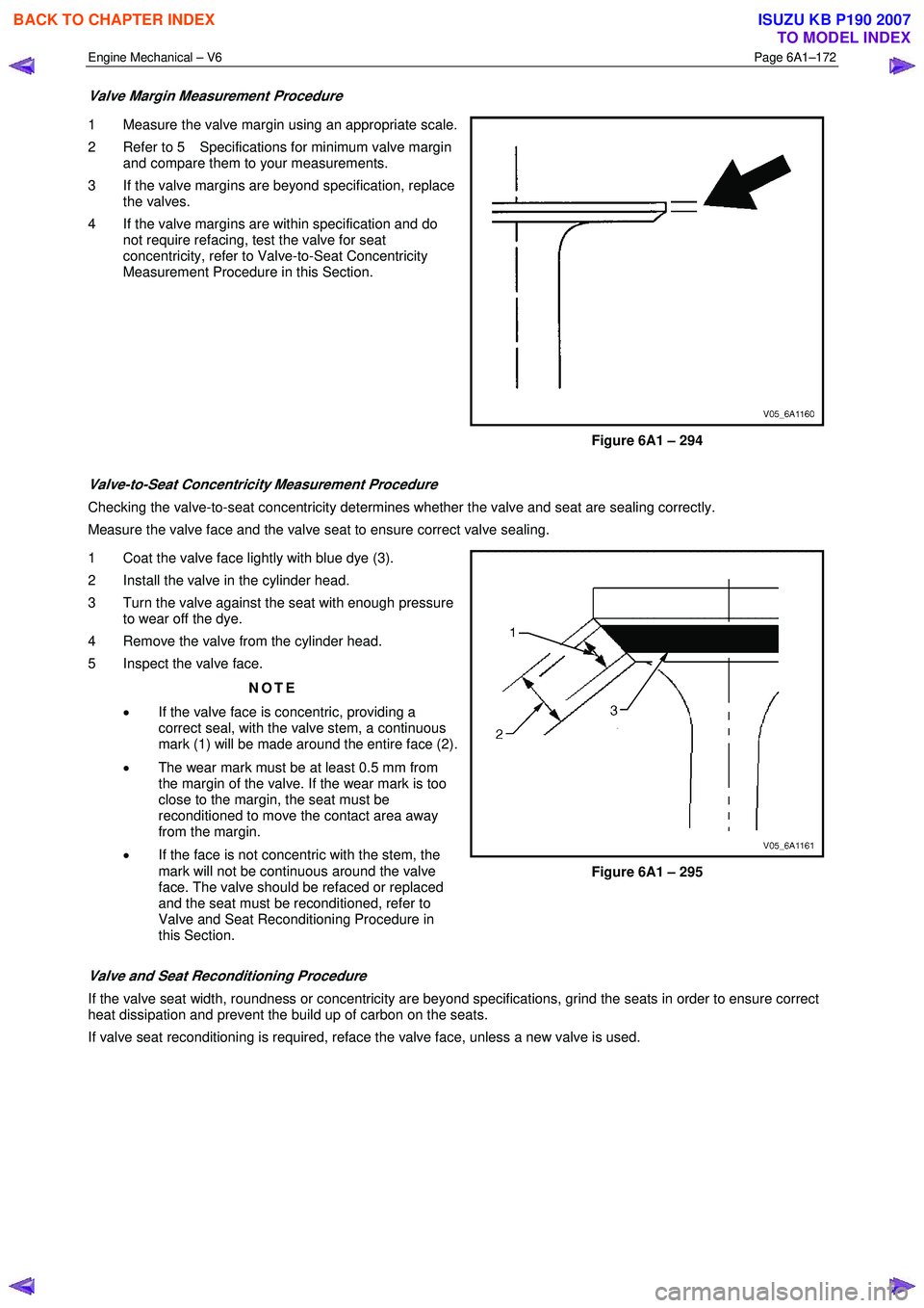
1 Measure the valve margin using an appropriate scale.
2 Refer to 5 Specifications for minimum valve margin and compare them to your measurements.
3 If the valve margins are beyond specification, replace the valves.
4 If the valve margins are within specification and do not require refacing, test the valve for seat
concentricity, refer to Valve-to-Seat Concentricity
Measurement Procedure in this Section.
Figure 6A1 – 294
Valve-to-Seat Concentricity Measurement Procedure
Checking the valve-to-seat concentricity determines whether the valve and seat are sealing correctly.
Measure the valve face and the valve seat to ensure correct valve sealing.
1 Coat the valve face lightly with blue dye (3).
2 Install the valve in the cylinder head.
3 Turn the valve against the seat with enough pressure to wear off the dye.
4 Remove the valve from the cylinder head.
5 Inspect the valve face.
NOTE
• If the valve face is concentric, providing a
correct seal, with the valve stem, a continuous
mark (1) will be made around the entire face (2).
• The wear mark must be at least 0.5 mm from
the margin of the valve. If the wear mark is too
close to the margin, the seat must be
reconditioned to move the contact area away
from the margin.
• If the face is not concentric with the stem, the
mark will not be continuous around the valve
face. The valve should be refaced or replaced
and the seat must be reconditioned, refer to
Valve and Seat Reconditioning Procedure in
this Section.
Figure 6A1 – 295
Valve and Seat Reconditioning Procedure
If the valve seat width, roundness or concentricity are beyond specifications, grind the seats in order to ensure correct
heat dissipation and prevent the build up of carbon on the seats.
If valve seat reconditioning is required, reface the valve face, unless a new valve is used.
BACK TO CHAPTER INDEX
TO MODEL INDEX
ISUZU KB P190 2007
Page 2660 of 6020
Engine Mechanical – V6 Page 6A1–181
3.23 Engine Mounts and Brackets
Remove
1 Remove the exhaust manifold assembly from the side of the engine where the engine mount is to be removed,
refer to 3.11 Exhaust Manifold Assembly.
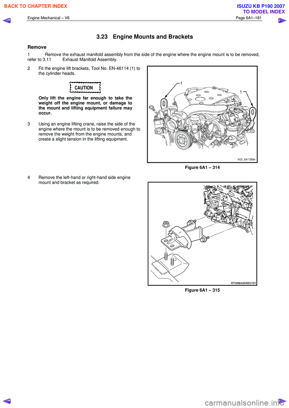
2 Fit the engine lift brackets, Tool No. EN-46114 (1) to the cylinder heads.
CAUTION
Only lift the engine far enough to take the
weight off the engine mount, or damage to
the mount and lifting equipment failure may
occur.
3 Using an engine lifting crane, raise the side of the engine where the mount is to be removed enough to
remove the weight from the engine mounts, and
create a slight tension in the lifting equipment.
Figure 6A1 – 314
4 Remove the left-hand or right-hand side engine mount and bracket as required.
Figure 6A1 – 315
BACK TO CHAPTER INDEX
TO MODEL INDEX
ISUZU KB P190 2007
Page 2661 of 6020
Engine Mechanical – V6 Page 6A1–182
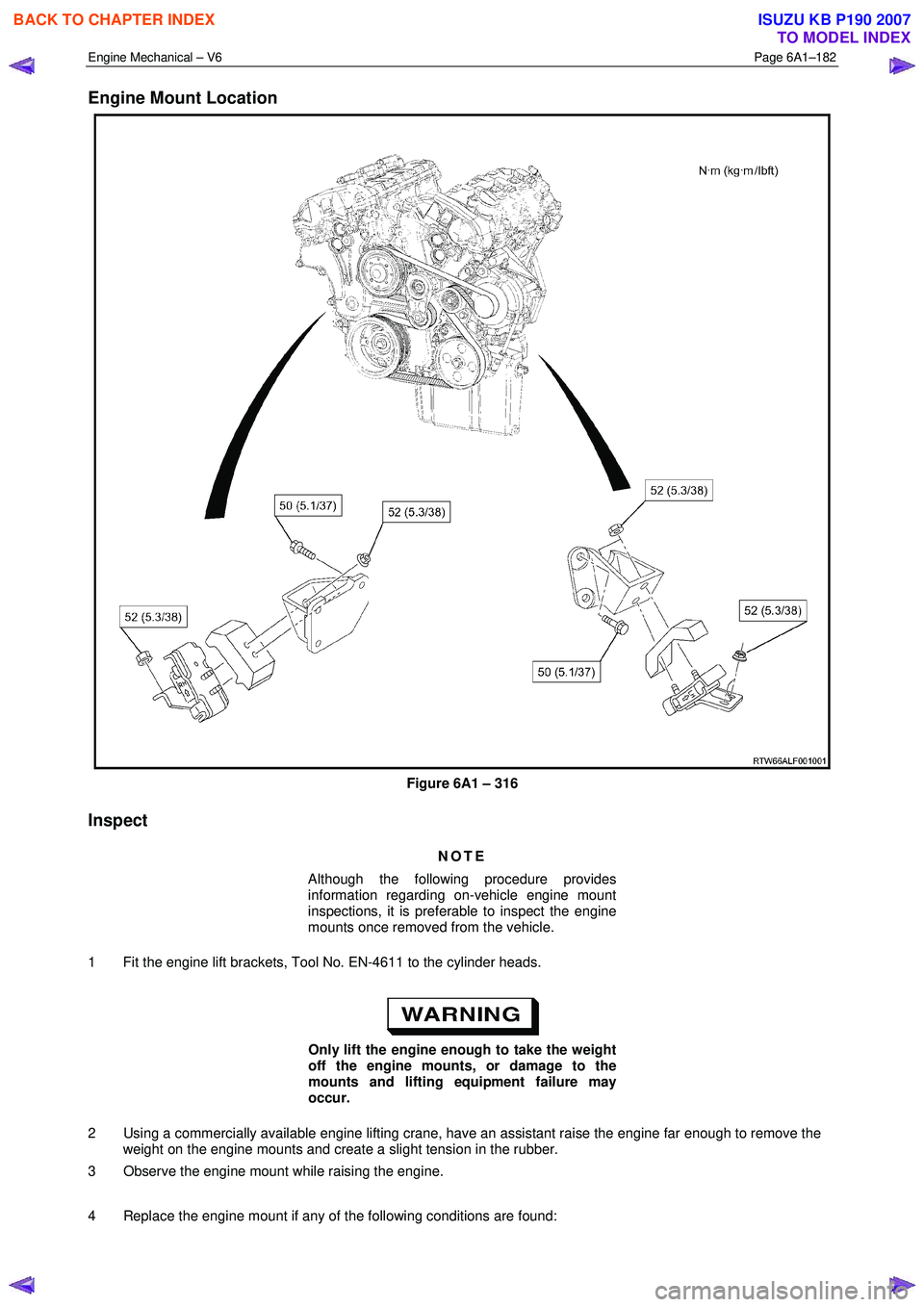
Engine Mount Location
Figure 6A1 – 316
Inspect
NOTE
Although the following procedure provides
information regarding on-vehicle engine mount
inspections, it is preferable to inspect the engine
mounts once removed from the vehicle.
1 Fit the engine lift brackets, Tool No. EN-4611 to the cylinder heads.
Only lift the engine enough to take the weight
off the engine mounts, or damage to the
mounts and lifting equipment failure may
occur.
2 Using a commercially available engine lifting crane, have an assistant raise the engine far enough to remove the weight on the engine mounts and create a slight tension in the rubber.
3 Observe the engine mount while raising the engine.
4 Replace the engine mount if any of the following conditions are found:
BACK TO CHAPTER INDEX
TO MODEL INDEX
ISUZU KB P190 2007
Page 2694 of 6020
Engine Mechanical – V6 Page 6A1–215
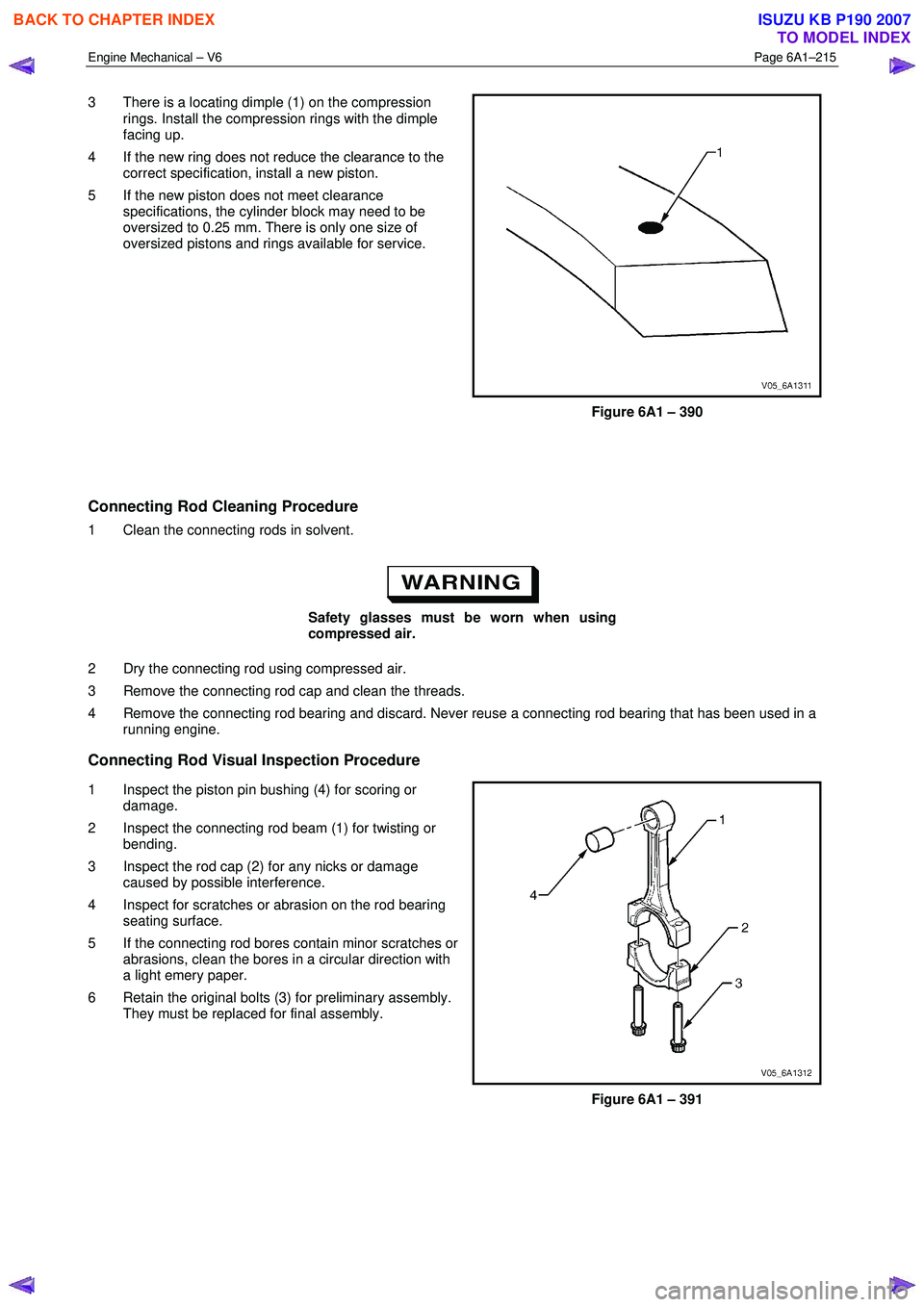
3 There is a locating dimple (1) on the compression
rings. Install the compression rings with the dimple
facing up.
4 If the new ring does not reduce the clearance to the correct specification, install a new piston.
5 If the new piston does not meet clearance specifications, the cylinder block may need to be
oversized to 0.25 mm. There is only one size of
oversized pistons and rings available for service.
Figure 6A1 – 390
Connecting Rod Cleaning Procedure
1 Clean the connecting rods in solvent.
Safety glasses must be worn when using
compressed air.
2 Dry the connecting rod using compressed air.
3 Remove the connecting rod cap and clean the threads.
4 Remove the connecting rod bearing and discard. Never reuse a connecting rod bearing that has been used in a running engine.
Connecting Rod Visual Inspection Procedure
1 Inspect the piston pin bushing (4) for scoring or
damage.
2 Inspect the connecting rod beam (1) for twisting or bending.
3 Inspect the rod cap (2) for any nicks or damage caused by possible interference.
4 Inspect for scratches or abrasion on the rod bearing seating surface.
5 If the connecting rod bores contain minor scratches or abrasions, clean the bores in a circular direction with
a light emery paper.
6 Retain the original bolts (3) for preliminary assembly. They must be replaced for final assembly.
Figure 6A1 – 391
BACK TO CHAPTER INDEX
TO MODEL INDEX
ISUZU KB P190 2007
Page 2701 of 6020
Engine Mechanical – V6 Page 6A1–222
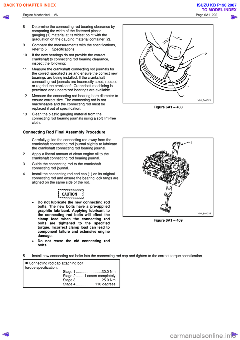
8 Determine the connecting rod bearing clearance by
comparing the width of the flattened plastic
gauging (1) material at its widest point with the
graduation on the gauging material container (2).
9 Compare the measurements with the specifications, refer to 5 Specifications.
10 If the new bearings do not provide the correct crankshaft to connecting rod bearing clearance,
inspect the following:
11 Measure the crankshaft connecting rod journals for the correct specified size and ensure the correct new
bearings are being installed. If the crankshaft
connecting rod journals are incorrectly sized, replace
or regrind the crankshaft. Crankshaft machining is
permitted and undersized bearings are available.
12 Measure the connecting rod bearing bore diameter to ensure correct size. The connecting rod is not
machineable and the connecting rod must be
replaced if out of specification.
13 Clean the plastic gauging material from the connecting rod bearing journals using a soft lint-free
cloth.
Figure 6A1 – 408
Connecting Rod Final Assembly Procedure
1 Carefully guide the connecting rod away from the crankshaft connecting rod journal slightly to lubricate
the crankshaft connecting rod bearing journal.
2 Apply a liberal amount of clean engine oil to the crankshaft connecting rod bearing journal.
3 Guide the connecting rod to the crankshaft connecting rod journal.
4 Install the connecting rod end cap (1) on its original connecting rod and ensure the bearing lock tangs are
aligned on the same side of the rod.
CAUTION
• Do not lubricate the new connecting rod
bolts. The new bolts have a pre-applied
graphite lubricant. Applying lubricant to
the connecting rod bolts will effect the
clamp load when the connecting rod
bolts are tightened to the specified
torque. Incorrect clamp load can lead to
component failure and extensive engine
damage.
• Do not reuse the old connecting rod
bolts.
Figure 6A1 – 409
5 Install new connecting rod bolts into the connecting rod cap and tighten to the correct torque specification. �„ Connecting rod cap attaching bolt
torque specification:
Stage 1 .........................30.0 Nm
Stage 2 ........ Loosen completely
Stage 3 .........................25.0 Nm
Stage 4 .................. 110 degrees
BACK TO CHAPTER INDEX
TO MODEL INDEX
ISUZU KB P190 2007
Page 2712 of 6020
Engine Mechanical – V6 Page 6A1–233
Crankshaft Final Installation Procedure
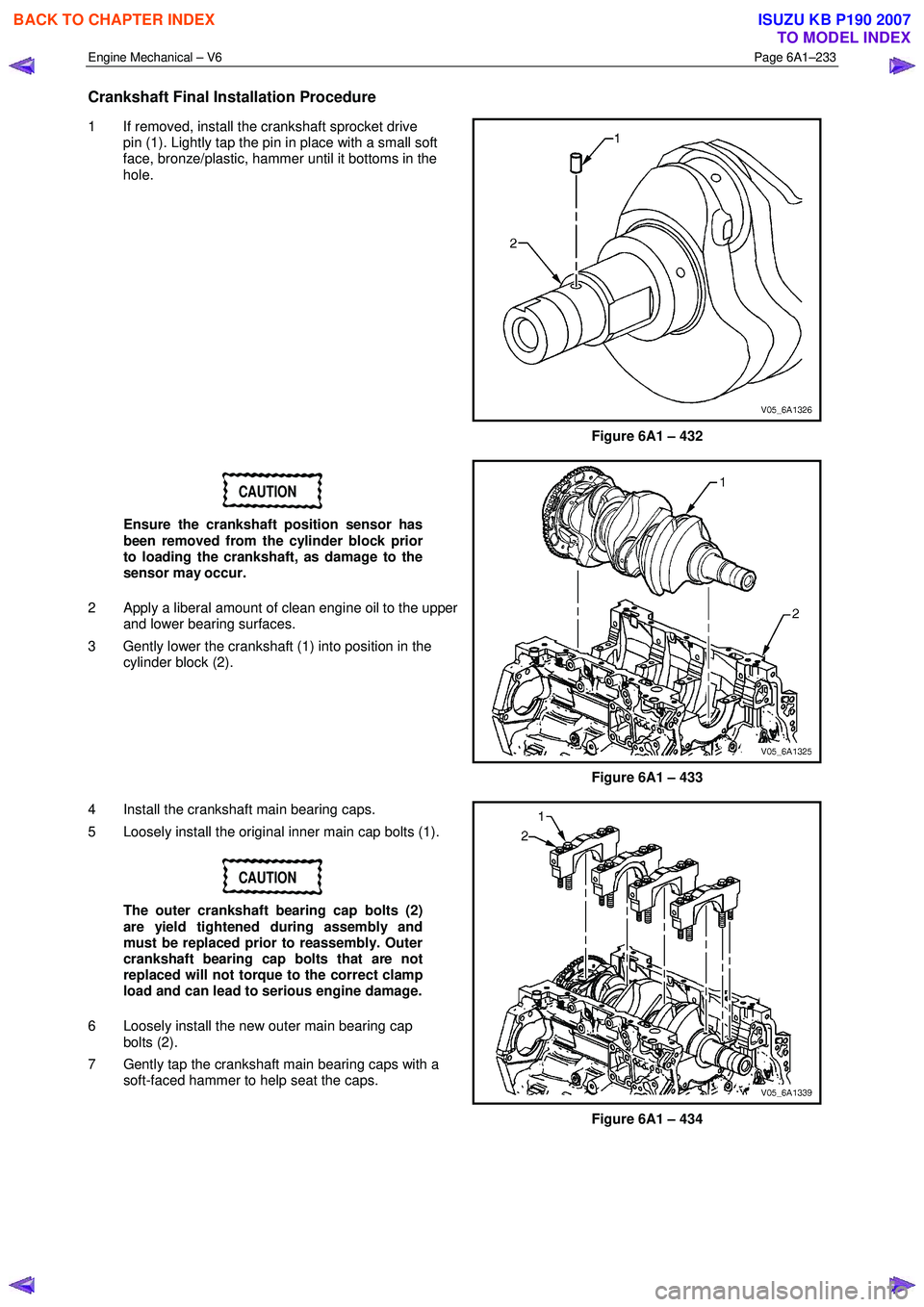
1 If removed, install the crankshaft sprocket drive
pin (1). Lightly tap the pin in place with a small soft
face, bronze/plastic, hammer until it bottoms in the
hole.
Figure 6A1 – 432
CAUTION
Ensure the crankshaft position sensor has
been removed from the cylinder block prior
to loading the crankshaft, as damage to the
sensor may occur.
2
Apply a liberal amount of clean engine oil to the upper
and lower bearing surfaces.
3 Gently lower the crankshaft (1) into position in the cylinder block (2).
Figure 6A1 – 433
4 Install the crankshaft main bearing caps.
5 Loosely install the original inner main cap bolts (1).
CAUTION
The outer crankshaft bearing cap bolts (2)
are yield tightened during assembly and
must be replaced prior to reassembly. Outer
crankshaft bearing cap bolts that are not
replaced will not torque to the correct clamp
load and can lead to serious engine damage.
6 Loosely install the new outer main bearing cap bolts (2).
7 Gently tap the crankshaft main bearing caps with a soft-faced hammer to help seat the caps.
Figure 6A1 – 434
BACK TO CHAPTER INDEX
TO MODEL INDEX
ISUZU KB P190 2007