2007 ISUZU KB P190 light
[x] Cancel search: lightPage 5892 of 6020
IMMOBILIZER CONTROL SYSTEM (4JK1/4JJ1/HFV6) 11A-41
a. Connect a scan tool to the terminal thatinstalled TIS 2000 with the latest software and
the hardware key is plugged into port.
b. Turn ON the scan tool and keep at title screen.
c. Launch the TIS application.
d. Select the Security Access at the main screen.
e. Highlight "Tech 2" on the Diagnostic Tool Selection screen and click "Next".
f. Click "Close" on the Security Access Enabled screen.
g. Turn OFF the scan tool.
h. Disconnect the scan tool from the terminal.
5. Reinstall a scan tool to the vehicle.
6. Turn ON the ignition, with the engine OFF.
7. Select Diagnostics > Appropriate vehicle identification > Body > Immobilizer > Programming
> Immobilizer Link To ECM/ PIM.
8. Select "Immobilizer Replaced" No and select "PIM or ECM Replaced" Yes.
9. Input four digits of correct security code that belongs to this vehicle and follow the on-screen
instructions. The on-screen instruction repeats
twice.
Notice: An incorrect security code input causes a
security wait time.
10. Select "PIM Replaced". 11. Operate the ignition switch by following the on- screen instructions.
12. The on-screen displays a message "Programming Successfully!" if PIM programming has been
completed, the press Confirm.
ICU & PIM Programming Procedure
1. Install a scan tool.
2. Turn ON the ignition, with the engine OFF.
3. Select Diagnostics > Appropriate vehicle identification > Body > Immobilizer > Programming
> Immobilizer Link To ECM/ PIM.
4. In order to get a programming approval, the onscreen displays a message to user. Get
programming approval from the TIS 2000 using
the following procedure:
a. Connect a scan tool to the terminal that installed TIS 2000 with the latest software and
the hardware key is plugged into port.
b. Turn ON the scan tool and keep at title screen.
c. Launch the TIS application.
d. Select the Security Access at the main screen.
e. Highlight "Tech 2" on the Diagnostic Tool Selection screen and click "Next".
f. Click "Close" on the Security Access Enabled screen. g. Turn OFF the scan tool.
h. Disconnect the scan tool from the terminal.
5. Reinstall a scan tool to the vehicle.
6. Turn ON the ignition, with the engine OFF.
7. Select Diagnostics > Appropriate vehicle identification > Body > Immobilizer > Programming
> Immobilizer Link To ECM/ PIM.
8. Select "Immobilizer Replaced" Yes and select "PIM or ECM Replaced" Yes.
9. Input four digits of correct security code that belongs to this vehicle and follow the on-screen
instructions. The on-screen instruction repeats
twice.
Notice: An incorrect security code input causes a
security wait time.
10. Select "PIM Replaced". 11. Input 17 digits of correct VIN that is based on stamped VIN or affixed VIN plate on this vehicle.
12. Operate the ignition switch by following the onscreen instructions.
Notice: Keep away another key, another transponder
key, key number plate or other metal items from the
transponder key that is going to program.
13. The on-screen displays a message "Program more Transponder Keys?" If all transponder key(s) has
been programmed, press No and go to next step. If
more transponder key(s) need to be programmed,
press Yes and repeat from previous step.
14. The on-screen displays a message "Programming Successfully!" if ICU, PIM and all transponder
key(s) programming has been completed, the
press Confirm.
15. Turn OFF the ignition for 30 seconds.
16. Verify the engine starts using all programmed transponder key(s).
ECM & PIM Programming Procedure
1. Install a scan tool.
2. Turn ON the ignition, with the engine OFF.
3. Select Diagnostics > Appropriate vehicle identification > Body > Immobilizer > Programming
> Immobilizer Link To ECM/ PIM.
4. In order to get a programming approval, the onscreen displays a message to user. Get
programming approval from the TIS 2000 using
the following procedure:
a. Connect a scan tool to the terminal that installed TIS 2000 with the latest software and
the hardware key is plugged into port.
b. Turn ON the scan tool and keep at title screen.
c. Launch the TIS application.
d. Select the Security Access at the main screen.
BACK TO CHAPTER INDEX TO MODEL INDEX
ISUZU KB P190 2007
Page 5893 of 6020
11A-42 IMMOBILIZER CONTROL SYSTEM (4JK1/4JJ1/HFV6)
e. Highlight "Tech 2" on the Diagnostic ToolSelection screen and click "Next".
f. Click "Close" on the Security Access Enabled screen.
g. Turn OFF the scan tool.
h. Disconnect the scan tool from the terminal.
5. Reinstall a scan tool to the vehicle.
6. Turn ON the ignition, with the engine OFF.
7. Select Diagnostics > Appropriate vehicle identification > Body > Immobilizer > Programming
> Immobilizer Link To ECM/ PIM.
8. Select "Immobilizer Replaced" No and select "PIM or ECM Replaced" Yes.
9. Input four digits of correct security code that belongs to this vehicle and follow the on-screen
instructions. The on-screen instruction repeats
twice.
Notice: An incorrect security code input causes a
security wait time.
10. Select "PIM and ECM Replaced". 11. Operate the ignition switch by following the on- screen instructions.
12. The on-screen displays a message "Programming Successfully!" if ECM and PIM programming has
been completed, the press Confirm.
ICU & ECM Programming Procedure
1. Install a scan tool.
2. Turn ON the ignition, with the engine OFF.
3. Select Diagnostics > Appropriate vehicle identification > Body > Immobilizer > Programming
> Program Immobilizer Function or Immobilizer
Link To ECM/ PIM.
4. In order to get a programming approval, the on- screen displays a message to user. Get
programming approval from the TIS 2000 using
the following procedure:
a. Connect a scan tool to the terminal that installed TIS 2000 with the latest software and
the hardware key is plugged into port.
b. Turn ON the scan tool and keep at title screen.
c. Launch the TIS application.
d. Select the Security Access at the main screen.
e. Highlight "Tech 2" on the Diagnostic Tool Selection screen and click "Next".
f. Click "Close" on the Security Access Enabled screen.
g. Turn OFF the scan tool.
h. Disconnect the scan tool from the terminal.
5. Reinstall a scan tool to the vehicle.
6. Turn ON the ignition, with the engine OFF. 7. Select Diagnostics > Appropriate vehicle
identification > Body > Immobilizer > Programming
> Program Immobilizer Function or Immobilizer
Link To ECM/ PIM.
8. The on-screen may display a message "See Checking Procedure Before Programming!", then
press Confirm.
9. Select "Immobilizer and ECM Installed" or select "Immobilizer Replaced" Yes.
10. Select "PIM or ECM Replaced" Yes, if displayed. 11. Input four digits of correct security code that belongs to this vehicle and follow the on-screen
instructions. The on-screen instruction repeats
twice.
Notice: An incorrect security code input causes a
security wait time.
12. Select "ECM Replaced" if displayed.
13. Input 17 digits of correct VIN that is based on stamped VIN or affixed VIN plate on this vehicle.
14. Operate the ignition switch by following the on- screen instructions.
Notice: Keep away another key, another transponder
key, key number plate or other metal items from the
transponder key that is going to program.
15. The on-screen displays a message "Program more Transponder Keys?" If all transponder key(s) has
been programmed, press No and go to next step. If
more transponder key(s) need to be programmed,
press Yes and repeat from previous step.
16. The on-screen displays a message "Programming Successfully!" if ICU, ECM and all transponder
key(s) programming has been completed, then
press Confirm.
17. Turn OFF the ignition for 30 seconds.
18. Verify the engine starts using all programmed transponder key(s).
ICU, ECM & PIM Programming Procedure
1. Install a scan tool.
2. Turn ON the ignition, with the engine OFF.
3. Select Diagnostics > Appropriate vehicle identification > Body > Immobilizer > Programming
> Immobilizer Link To ECM/ PIM.
4. In order to get a programming approval, the onscreen displays a message to user. Get
programming approval from the TIS 2000 using
the following procedure:
a. Connect a scan tool to the terminal that installed TIS 2000 with the latest software and
the hardware key is plugged into port.
b. Turn ON the scan tool and keep at title screen.
c. Launch the TIS application.
d. Select the Security Access at the main screen.
BACK TO CHAPTER INDEX TO MODEL INDEX
ISUZU KB P190 2007
Page 5894 of 6020
IMMOBILIZER CONTROL SYSTEM (4JK1/4JJ1/HFV6) 11A-43
e. Highlight "Tech 2" on the Diagnostic ToolSelection screen and click "Next".
f. Click "Close" on the Security Access Enabled screen.
g. Turn OFF the scan tool.
h. Disconnect the scan tool from the terminal.
5. Reinstall a scan tool to the vehicle.
6. Turn ON the ignition, with the engine OFF.
7. Select Diagnostics > Appropriate vehicle identification > Body > Immobilizer > Programming
> Immobilizer Link To ECM/ PIM.
8. Select "Immobilizer Replaced" Yes and select "PIM or ECM Replaced" Yes.
9. Input four digits of correct security code that belongs to this vehicle and follow the on-screen
instructions. The on-screen instruction repeats
twice.
Notice: An incorrect security code input causes a
security wait time.
10. Select "PIM and ECM Replaced". 11. Input 17 digits of correct VIN that is based on stamped VIN or affixed VIN plate on this vehicle.
12. Operate the ignition switch by following the onscreen instructions.
Notice: Keep away another key, another transponder
key, key number plate or other metal items from the
transponder key that is going to program.
13. The on-screen displays a message "Program more Transponder Keys?" If all transponder key(s) has
been programmed, press No and go to next step. If
more transponder key(s) need to be programmed,
press Yes and repeat from previous step.
14. The on-screen displays a message "Programming Successfully!" if ICU, ECM, PIM and all
transponder key(s) programming has been
completed, the press Confirm.
15. Turn OFF the ignition for 30 seconds.
16. Verify the engine starts using all programmed transponder key(s).
BACK TO CHAPTER INDEX TO MODEL INDEX
ISUZU KB P190 2007
Page 5956 of 6020
11B-2 ANTITHEFT SYSTEM
Service Precaution
WARNING: THIS VEHICLE HAS A SUPPLEMENTAL
RESTRAINT SYSTEM (SRS). REFER TO THE SRS
COMPONENT AND WIRING LOCATION VIEW IN
ORDER TO DETERMINE WHETHER YOU ARE
PERFORMING SERVICE ON OR NEAR THE SRS
COMPONENTS OR THE SRS WIRING. WHEN YOU
ARE PERFORMING SERVICE ON OR NEAR THE
SRS COMPONENTS OR THE SRS WIRING, REFER
TO THE SRS SERVICE INFORMATION. FAILURE TO
FOLLOW WARNINGS COULD RESULT IN
POSSIBLE AIR BAG DEPLOYMENT, PERSONAL
INJURY, OR OTHERWISE UNNEEDED SRS SYSTEM
REPAIRS.
CAUTION: Always use the correct fastener in the
proper location. When you replace a fastener, use
ONLY the exact part number for that application.
ISUZU will call out those fasteners that require a
replacement after removal. ISUZU will also call out
the fasteners that require thread lockers or thread
sealant. UNLESS OTHERWISE SPECIFIED, do not
use supplemental coatings (Paints, greases, or
other corrosion inhibitors) on threaded fasteners or
fastener joint interfaces. Generally, such coatings
adversely affect the fastener torque and the joint
clamping force, and may damage the fastener.
When you install fasteners, use the correct
tightening sequence and specifications. Following
these instructions can help you avoid damage to
parts and systems.
General Description
The Antitheft system consists of the four major
components which are Antitheft Control Unit (ACU),
Antitheft horn, key (remote key), and scan tool (Tech-2).
This system can be activated by a correctly
programmed key (remote key) and starter switch is set
to OFF.
This system can be deactivated by a correctly
programmed key (remote key) connected with a
correctly programmed ACU and a correctly
programmed lCU.
W hen the vehicle doors, and engine hood are locked,
the antitheft alarm system is designed to protect your
vehicle and valuables from theft.
Any attempt to forcibly open any door, the engine hood
without using the vehicle key (or remote control) will
cause the hazard lights to flash on and off and the horn
to sound intermittently. This will continue for 30 seconds
(Hazard lamp flash; For 5 minutes) before the system
automatically shuts itself off.
Please operate the door either the key lock or remote
key after closing all doors to arm the alarm system.
Miss waning will be detected when the passenger door
is opened with locked condition and then this door is
closed.
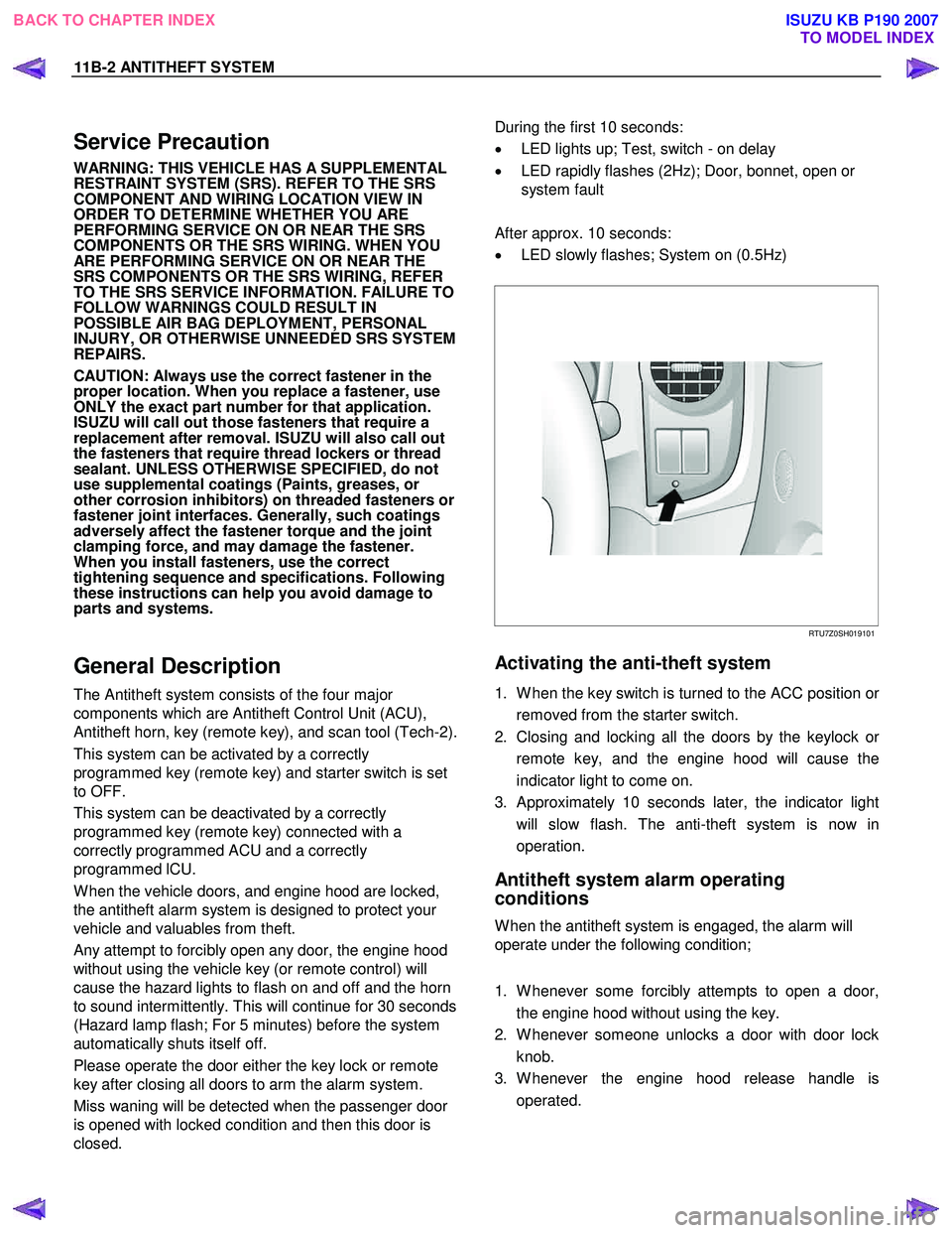
During the first 10 seconds:
• LED lights up; Test, switch - on delay
• LED rapidly flashes (2Hz); Door, bonnet, open or
system fault
After approx. 10 seconds:
• LED slowly flashes; System on (0.5Hz)
RTU7Z0SH019101
Activating the anti-theft system
1. W hen the key switch is turned to the ACC position or
removed from the starter switch.
2. Closing and locking all the doors by the keylock o
r
remote key, and the engine hood will cause the
indicator light to come on.
3. Approximately 10 seconds later, the indicator light will slow flash. The anti-theft system is now in
operation.
Antitheft system alarm operating
conditions
W hen the antitheft system is engaged, the alarm will
operate under the following condition;
1. W henever some forcibly attempts to open a door, the engine hood without using the key.
2. W henever someone unlocks a door with door lock knob.
3. W henever the engine hood release handle is operated.
BACK TO CHAPTER INDEX TO MODEL INDEX
ISUZU KB P190 2007
Page 5957 of 6020
ANTITHEFT SYSTEM 11B-3
Function of a keyless entry system
W ith a keyless entry system the car can be locked or
unlocked from any position around the car up to a
specified distance, by using the potable radio remote
transmitter inside key (remote key).
Status LED
W hile the system is in delay the alarm system is active
and LED flashes at 0.5Hz with or without activated
interior protection.
Hazard relay
The hazard warning lights will be activated by an
external relay. The output is low active.
Switches
All switches to ground. This makes it possible for failure
analysis to detect a short circuit or a broken wire to
each switch. To use this feature it is necessary to place
a 1.8k Ω resistor in parallel to the required switch.
Receiver
The receiver is integrated into the control unit.
To lower the idle current the receiver is equipped with a
standby mode. The antenna is integrated on the printed
circuit board.
Depending on the mounting position of the control unit
the antenna can be connected externally.
Range of communication
The range of communication between remote key and
receiver is intended to be least 3 m from centre of the
car.
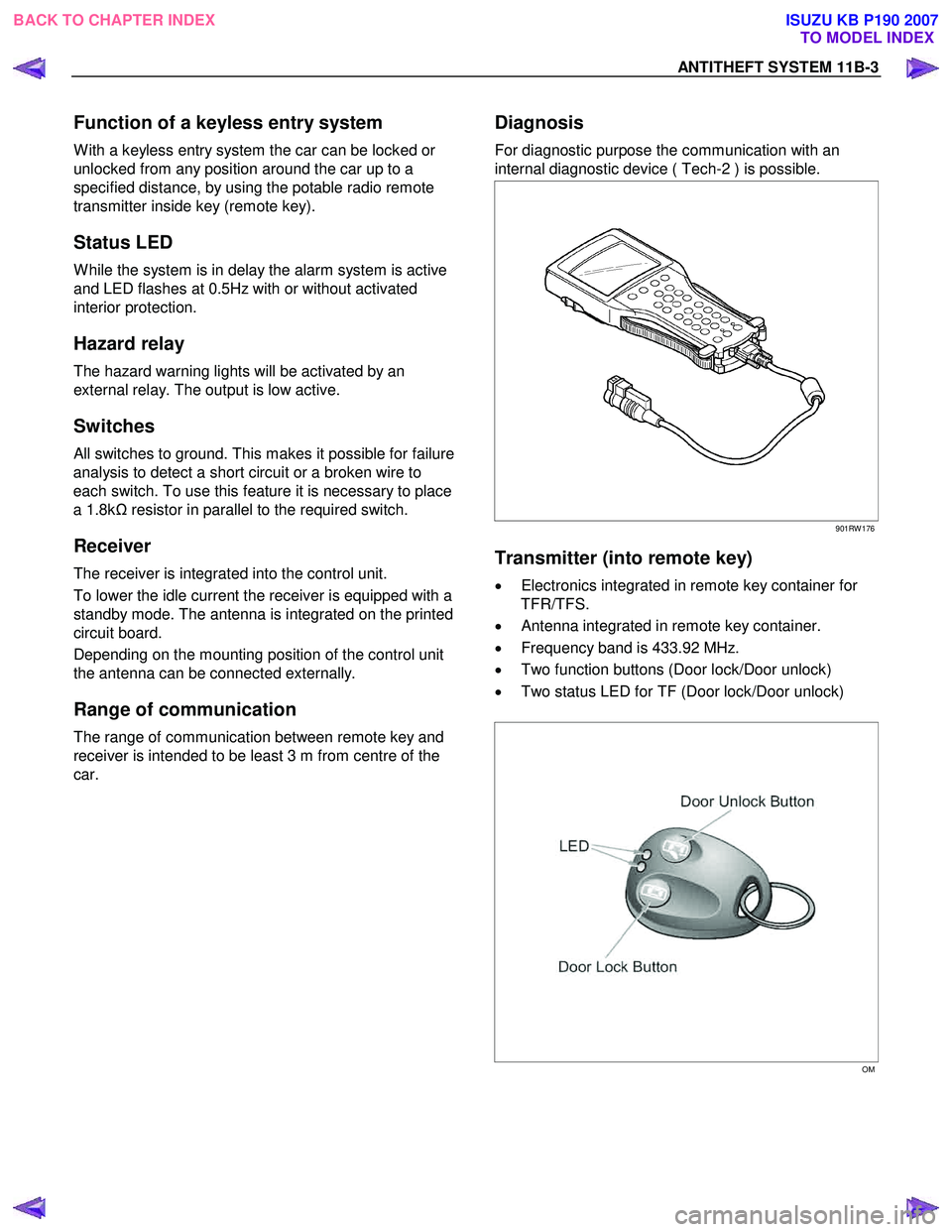
Diagnosis
For diagnostic purpose the communication with an
internal diagnostic device ( Tech-2 ) is possible.
901RW 176
Transmitter (into remote key)
• Electronics integrated in remote key container for
TFR/TFS.
• Antenna integrated in remote key container.
• Frequency band is 433.92 MHz.
• Two function buttons (Door lock/Door unlock)
• Two status LED for TF (Door lock/Door unlock)
OM
BACK TO CHAPTER INDEX TO MODEL INDEX
ISUZU KB P190 2007