Page 5567 of 6020
ELECTRICAL-BODY AND CHASSIS 8A-629
No. Connector face No. Connector face
M26
(C24SE)
Brown
2W D-4W D switch
M27
(C24SE)
Brown
Headlight leveling neutral switch
BACK TO CHAPTER INDEX
TO MODEL INDEXISUZU KB P190 2007
Page 5570 of 6020
8A-632 ELECTRICAL-BODY AND CHASSIS
No. Connector face No. Connector face
T1
NOT USED
T2
NOT USED
T3
Gray
License plate light-LH
T4
Gray
License plate light-RH
BACK TO CHAPTER INDEX
TO MODEL INDEXISUZU KB P190 2007
Page 5571 of 6020
ELECTRICAL-BODY AND CHASSIS 8A-633
No. Connector face No. Connector face
X1
Black
Fog light relay X8
BlackStarter relay
X2
(C24SE)
Black
Front fog light relay X9
BlackCondenser fan relay
X2
Black
Taillight relay X10
BlackTransmission relay
X3
Black
Horn relay X11
BlackHeater relay
X4
Black
Dimmer relay X12
BlackECM main relay
X5
Black
Glow relay X13
BlackFuel pump relay
X6
(C24SE)
Starter relay X13
(4JA1T- (L))
BlackCondenser fan relay
X6
Black
Headlight relay X14
BlackA/C compressor relay
X7
Black
Starter cut relay X14
(4JA1T- (L))
BlackStarter cut relay
X7
(4JA1T- (L))
Black
CSD relay X15
BlackThermo relay
BACK TO CHAPTER INDEX TO MODEL INDEXISUZU KB P190 2007
Page 5574 of 6020

8B-2 CRUISE CONTROL SYSTEM
General Description
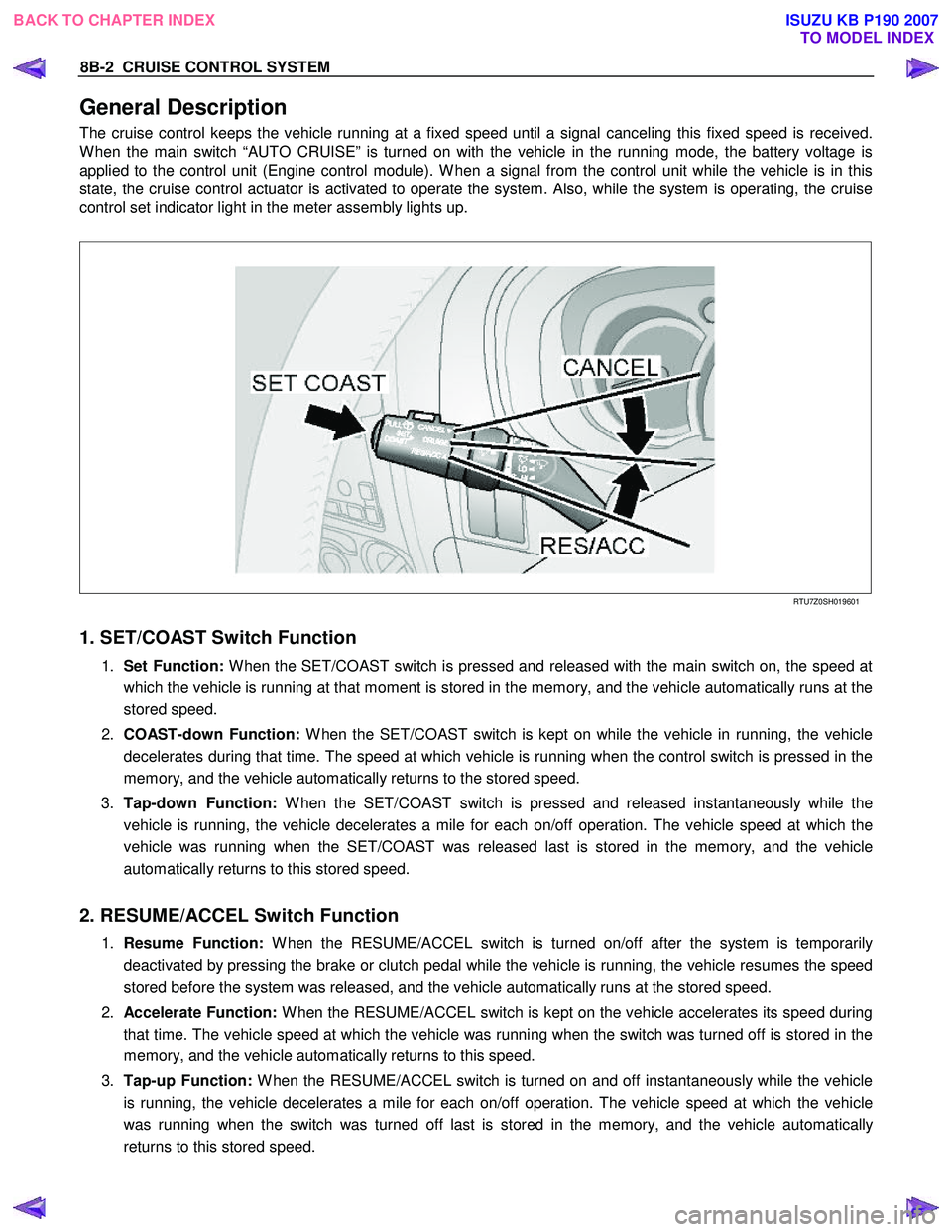
The cruise control keeps the vehicle running at a fixed speed until a signal canceling this fixed speed is received.
W hen the main switch “AUTO CRUISE” is turned on with the vehicle in the running mode, the battery voltage is
applied to the control unit (Engine control module). W hen a signal from the control unit while the vehicle is in this
state, the cruise control actuator is activated to operate the system. Also, while the system is operating, the cruise
control set indicator light in the meter assembly lights up.
RTU7Z0SH019601
1. SET/COAST Switch Function
1. Set Function: W hen the SET/COAST switch is pressed and released with the main switch on, the speed at
which the vehicle is running at that moment is stored in the memory, and the vehicle automatically runs at the
stored speed.
2. COAST-down Function: W hen the SET/COAST switch is kept on while the vehicle in running, the vehicle
decelerates during that time. The speed at which vehicle is running when the control switch is pressed in the
memory, and the vehicle automatically returns to the stored speed.
3. Tap-down Function: W hen the SET/COAST switch is pressed and released instantaneously while the
vehicle is running, the vehicle decelerates a mile for each on/off operation. The vehicle speed at which the
vehicle was running when the SET/COAST was released last is stored in the memory, and the vehicle
automatically returns to this stored speed.
2. RESUME/ACCEL Switch Function
1. Resume Function: W hen the RESUME/ACCEL switch is turned on/off after the system is temporarily
deactivated by pressing the brake or clutch pedal while the vehicle is running, the vehicle resumes the speed
stored before the system was released, and the vehicle automatically runs at the stored speed.
2. Accelerate Function: W hen the RESUME/ACCEL switch is kept on the vehicle accelerates its speed during
that time. The vehicle speed at which the vehicle was running when the switch was turned off is stored in the
memory, and the vehicle automatically returns to this speed.
3. Tap-up Function: W hen the RESUME/ACCEL switch is turned on and off instantaneously while the vehicle
is running, the vehicle decelerates a mile for each on/off operation. The vehicle speed at which the vehicle
was running when the switch was turned off last is stored in the memory, and the vehicle automatically
returns to this stored speed.
BACK TO CHAPTER INDEX TO MODEL INDEXISUZU KB P190 2007
Page 5578 of 6020
8B-6 CRUISE CONTROL SYSTEM
Cruise Control Main Switch
Removal
1. Disconnect the battery ground cable.
RTW 78ASH001801
2. Remove the side ventilation grille 1.
RTW 78ASH002301
3. Disconnect the switch connector and push the lock from the
backside of the side ventilation grille to remove the cruise
control main switch.
Installation
To install, follow the removal procedure in reverse order, noting
the following point.
1. Push in the switch with your fingers until it locks securely.
Cruise Control Switch (Combination Switch)
Removal and Installation
Refer to the Lighting Switch (Combination Switch) removal and
installation procedure of Lighting in Body and Chassis section.
BACK TO CHAPTER INDEX TO MODEL INDEXISUZU KB P190 2007
Page 5582 of 6020

Cruise Control – HFV6 Page 8C–4
NOTE Defined
A NOTE statement immediately precedes or follows an operating procedure, maintenance practice or condition that
requires highlighting. A NOTE statement also emphasises necessary characteristics of a diagnostic or repair procedure.
A NOTE statement is designed to:
• Clarify a procedure,
• Present additional information for accomplishing a procedure,
• Give insight into the reasons for performing a procedure in the recommended manner, and / or
• Present information that gives the technician the benefit of past experience in accomplishing a procedure with
greater ease.
1.2 System Components
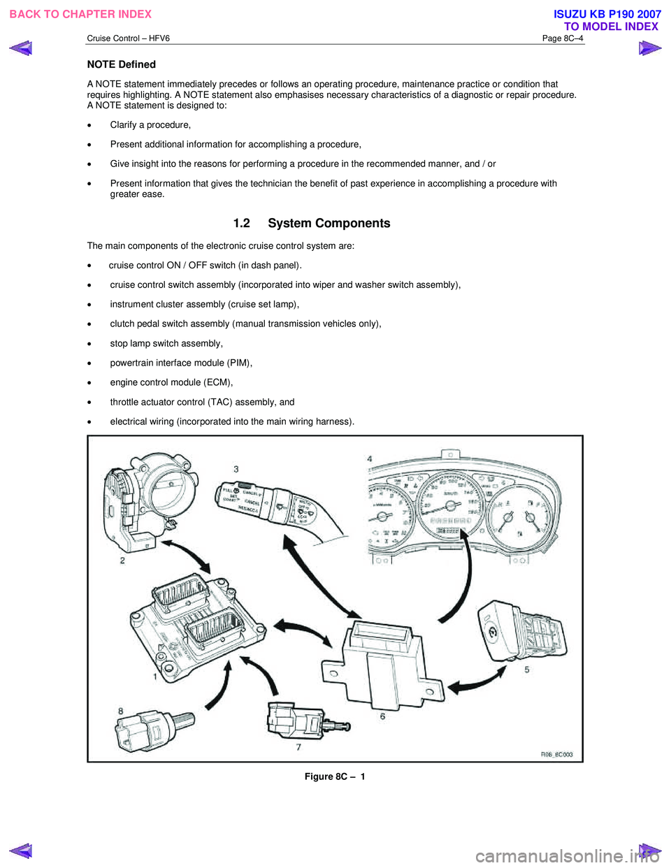
The main components of the electronic cruise control system are:
• cruise control ON / OFF switch (in dash panel).
• cruise control switch assembly (incorporated into wiper and washer switch assembly),
• instrument cluster assembly (cruise set lamp),
• clutch pedal switch assembly (manual transmission vehicles only),
• stop lamp switch assembly,
• powertrain interface module (PIM),
• engine control module (ECM),
• throttle actuator control (TAC) assembly, and
• electrical wiring (incorporated into the main wiring harness).
Figure 8C – 1
BACK TO CHAPTER INDEX TO MODEL INDEXISUZU KB P190 2007
Page 5593 of 6020

Cruise Control – HFV6 Page 8C–15
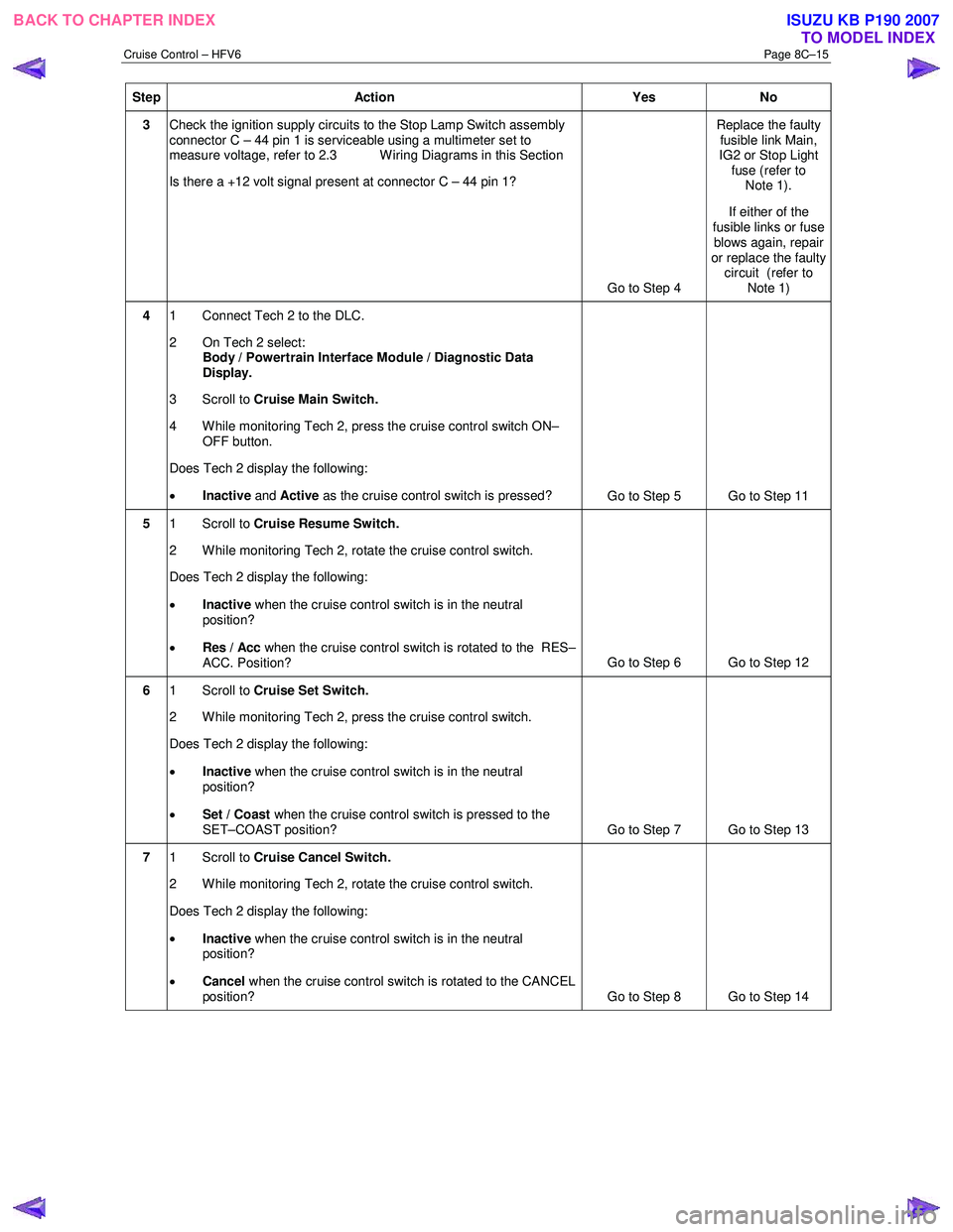
Step Action Yes No
3 Check the ignition supply circuits to the Stop Lamp Switch assembly
connector C – 44 pin 1 is serviceable using a multimeter set to
measure voltage, refer to 2.3 W iring Diagrams in this Section
Is there a +12 volt signal present at connector C – 44 pin 1?
Go to Step 4 Replace the faulty
fusible link Main,
IG2 or Stop Light fuse (refer to Note 1).
If either of the
fusible links or fuse blows again, repair
or replace the faulty circuit (refer to
Note 1)
4 1 Connect Tech 2 to the DLC.
2 On Tech 2 select: Body / Powertrain Interface Module / Diagnostic Data
Display.
3 Scroll to Cruise Main Switch.
4 W hile monitoring Tech 2, press the cruise control switch ON– OFF button.
Does Tech 2 display the following:
• Inactive and Active as the cruise control switch is pressed?
Go to Step 5 Go to Step 11
5 1 Scroll to Cruise Resume Switch.
2 While monitoring Tech 2, rotate the cruise control switch.
Does Tech 2 display the following:
• Inactive when the cruise control switch is in the neutral
position?
• Res / Acc when the cruise control switch is rotated to the RES–
ACC. Position? Go to Step 6 Go to Step 12
6
1 Scroll to Cruise Set Switch.
2 W hile monitoring Tech 2, press the cruise control switch.
Does Tech 2 display the following:
• Inactive when the cruise control switch is in the neutral
position?
• Set / Coast when the cruise control switch is pressed to the
SET–COAST position? Go to Step 7 Go to Step 13
7 1 Scroll to Cruise Cancel Switch.
2 While monitoring Tech 2, rotate the cruise control switch.
Does Tech 2 display the following:
• Inactive when the cruise control switch is in the neutral
position?
• Cancel when the cruise control switch is rotated to the CANCEL
position? Go to Step 8 Go to Step 14
BACK TO CHAPTER INDEX
TO MODEL INDEXISUZU KB P190 2007
Page 5627 of 6020
9-22 ACCESSORIES
CONNECTOR LIST
No. Connector face No. Connector face
B-10
White
Clock B-64
SilverW eld splice 1 (Illumination)
B-14
Gray
Audio B-65
SilverW eld splice 2 (Ground)
B-20
White
Cigar lighter illumination B-88
SilverW eld splice 5
B-21
White
Cigar lighter C-2
SilverEngine room –RH ground
B-22
Black
Cigar lighter C-108
White
J/B E1
B-41
White
Acc socket D-3
BlackFront speaker -RH
B-42
White
Acc socket D-8
BlackFront speaker -LH
B-55
White
J/B I3 D-13
BlackRear speaker -LH
B-56
White
J/B I4 D-17
BlackRear speaker -RH
B-62
White
Ignition switch (IGSUB: G1) D-21
WhiteTweeter -RH
BACK TO CHAPTER INDEX TO MODEL INDEXISUZU KB P190 2007