Page 5200 of 6020

8A-262 ELECTRICAL-BODY AND CHASSIS
Installation
Follow the removal procedure in the reverse order to install the
spot light.
Pay close attention to the important points mentioned in the
following paragraphs.
Connector
Be absolutely sure that the spot light connector is securely
connected.
This will prevent a poor contact and an open circuit.
Bulb
Be absolutely sure that the spot light bulb is correctly installed.
This will prevent a poor contact and an open circuit.
RUW 580SH001501
RUW 580SH001601
OVER HEAD CONSOLE (MAP Light)
Removal
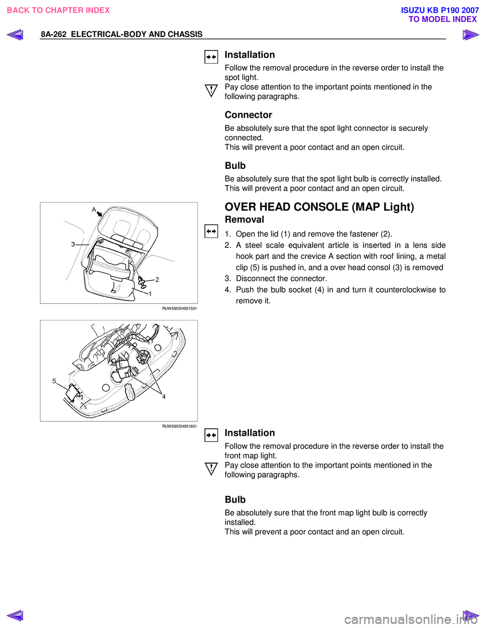
1. Open the lid (1) and remove the fastener (2).
2. A steel scale equivalent article is inserted in a lens side hook part and the crevice A section with roof lining, a metal
clip (5) is pushed in, and a over head consol (3) is removed
3. Disconnect the connector.
4. Push the bulb socket (4) in and turn it counterclockwise to remove it.
Installation
Follow the removal procedure in the reverse order to install the
front map light.
Pay close attention to the important points mentioned in the
following paragraphs.
Bulb
Be absolutely sure that the front map light bulb is correctly
installed.
This will prevent a poor contact and an open circuit.
BACK TO CHAPTER INDEX TO MODEL INDEXISUZU KB P190 2007
Page 5201 of 6020
ELECTRICAL-BODY AND CHASSIS 8A-263
INSPECTION AND REPAIR
R9 R10
R1 R6
DOOR SWITCH
Door Switch Connections
Connector
SW No.
R9
R10
R1 R6
position Terminal No.
1 Body Ground
PUSHED
RELEASED
W arning function Operational conditions
Key left in starter switch The buzzer sounds when both the key remind switch and the front door
switch-driver side are turned on.
To stop the sound of the buzzer, turn OFF the starter switch and remove the
key from the starter switch.
Lighting switch left on The buzzer sounds when the starter switch is turned from the “ON” to “OFF”
position while the lighting switch is ON position.
To stop the sound of the buzzer, turn OFF the lighting switch.
B62 B63
KEY REMIND SWITCH (STARTER
SWITCH)
Switch Connections
Connector
No. B63
Starter Terminal
switch key position No.
2 4
Removed
OFF
ACC Inserted
ON
START
LOCK
BACK TO CHAPTER INDEX TO MODEL INDEXISUZU KB P190 2007
Page 5216 of 6020
8A-278 ELECTRICAL-BODY AND CHASSIS
REMOVAL AND INSTALLATION
WIPER AND WASHER SWITCH
Removal
Refer to the removal steps of the LIGHTING SW ITCH
(COMBINATION SW ITCH) in “ LIGHTING “ of this section.
Installation
Follow the removal procedure in the reverse order to install the
wiper and washer switch.
RTW 780SH001601
This illustration is based on RHD model
Pay close attention to the important points mentioned in the
following paragraphs.
Connector
Be absolutely sure that the wiper and washer switch connector
is securely connected.
This will prevent a poor contact and an open circuit.
BACK TO CHAPTER INDEX TO MODEL INDEXISUZU KB P190 2007
Page 5221 of 6020
ELECTRICAL-BODY AND CHASSIS 8A-283
Windshield Washer Spray
Be sure that the engine hood is completely closed before
checking the windshield washer spray adjustment.
W indshield W asher Spray Position: Refer to the illustration.
RTW 38DSF000201
Connector
Be absolutely sure that the wiper motor connector is securely
connected.
This will prevent a poor contact and an open circuit.
Note:
Windshield wiper arm and blade assembly configurations
are different for the right-hand and left-hand side of the
vehicle.
Be careful not to confuse the right-hand and left-hand side
assemblies.
This illustration is based on RHD model
WASHER TANK MOTOR
Removal
1. Remove the head light.
• Refer to the head light in this manual.
2. Remove the inner liner.
3. Pull out the clip washer filler.
4. Remove the washer tank nuts.
BACK TO CHAPTER INDEX TO MODEL INDEXISUZU KB P190 2007
Page 5241 of 6020
ELECTRICAL-BODY AND CHASSIS 8A-303
METER, WARNING LIGHT AND INDICATOR LIGHT
PARTS LOCATION (RHD)
RTW 78AXF038901 & RTW 78AXF045101
BACK TO CHAPTER INDEX
TO MODEL INDEXISUZU KB P190 2007
Page 5289 of 6020
ELECTRICAL-BODY AND CHASSIS 8A-351
WARNING AND INDICATOR LIGHT
1. When the parking brake lever is pulled, the brake indicator light does not light up
Checkpoint Trouble Cause Countermeasure
Replace or reinstall the bulb
Bulb burned out or loose
contact
NG
Adjust or replace the parking
brake SW .
Parking brake SW . installation
position and function
Incorrect SW . adjustment or
poor SW . point contact
Continuity between the
parking brake SW . connector
1
C39 (stick type), 1 R4
(lev er type), and 4
B23
(C24SE : 9
B23 )
Repair open circuit or
connector contact
Open circuit or poor connector
contact
NG
NG
OK
OK
Brake indicator light bulb
continuity
NG
OK
Continuity between the
parking brake SW . connector
1
C39 (stick type), 1 R4
(lev er type) and the ground
when the parking brake is
operated
Replace the parking brake
SW .
Parking brake SW .
malfunction
BACK TO CHAPTER INDEX TO MODEL INDEXISUZU KB P190 2007
Page 5290 of 6020

8A-352 ELECTRICAL-BODY AND CHASSIS
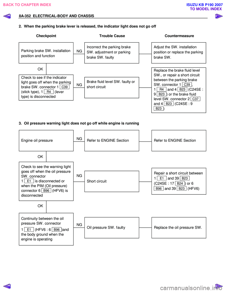
2. When the parking brake lever is released, the indicator light does not go off
Checkpoint Trouble Cause Countermeasure
Adjust the SW . installation
position or replace the parking
brake SW . Incorrect the parking brake
SW . adjustment or parking
brake SW . faulty
NG
Thermo unit malfunction
Replace the brake fluid level
SW ., or repair a short circuit
between the parking brake
SW . connector 1
C39,
1
R4 and 4 B23 (C24SE :
9
B23 ) or the brake fluid
level SW . connector 2
C37
and 4
B23 (C24SE : 9
B23 )
Check to see if the indicator
light goes off when the parking
brake SW . connector 1
C39
(stick type), 1
R4 (lever
type) is disconnected
Brake fluid level SW . faulty or
short circuit
NG
OK
Parking brake SW . installation
position and function
3. Oil pressure warning light does not go off while engine is running
Refer to ENGINE Section
Refer to ENGINE Section
NG Thermo unit malfunction
Check to see the warning light
goes off when the oil pressure
SW . connector
1
E1 is disconnected or
when the PIM (Oil pressure)
connector 6
B96 (HFV6) is
disconnected
Repair a short circuit between
1
E1 and 39 B23
(C24SE : 17
B24) or 6
B96 and 39 B23 (HFV6)
Short circuit
NG
OK
Replace the oil pressure SW .
Continuity between the oil
pressure SW . connector
1
E1 (HFV6 : 6 B96 )and
the body ground when the
engine is operating
Oil pressure SW . faulty
NG
OK
Engine oil pressure
BACK TO CHAPTER INDEX TO MODEL INDEXISUZU KB P190 2007
Page 5294 of 6020
8A-356 ELECTRICAL-BODY AND CHASSIS
INSPECTION AND REPAIR
METER AND INDICATOR LIGHT LAYOUT
Without tachometer (4JJ1-TC/4JK1-TC)
RTW 78AMF000501
With tachometer (4JJ1-TC/4JK1-TC)
RTW 78AMF000101
BACK TO CHAPTER INDEX TO MODEL INDEXISUZU KB P190 2007